
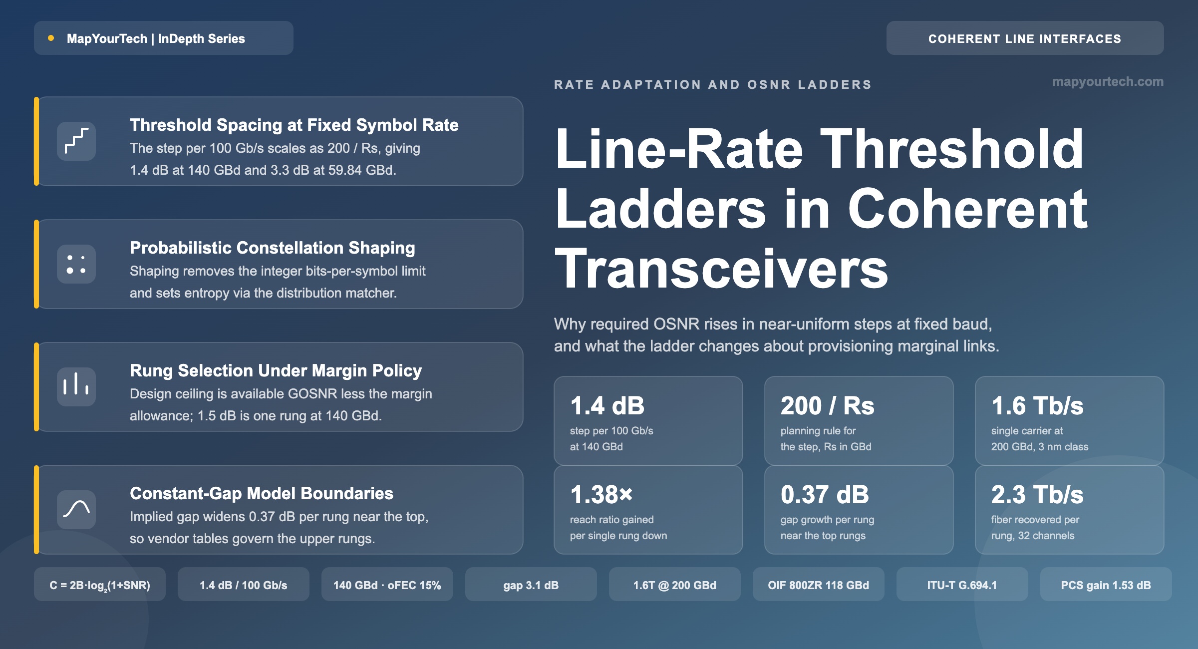
Line-Rate Threshold Ladders in Coherent Transceivers
At a fixed symbol rate the required optical signal-to-noise ratio (OSNR) of a modern coherent line interface rises in near-uniform steps of roughly 1.4 dB per 100 Gb/s, and that regular spacing turns a marginal link from a hardware problem into a provisioning decision.
1. Introduction
A 140 GBd coherent line card configured for 800 Gb/s needs about 23.0 dB of received optical signal-to-noise ratio. Drop the same card to 700 Gb/s and it needs 21.6 dB. Drop it again to 600 Gb/s and it needs 20.1 dB. Nothing in the module changed between those three states: the same laser, the same digital-to-analog converters, the same 140 GBd symbol clock, the same forward error correction. Only the number of information bits carried per symbol changed, and with it the noise the receiver can survive. Those numbers are model-derived for an open FEC (oFEC) class overhead of 15 % and a 3.1 dB implementation gap, and they sit within a few tenths of a decibel of the per-rate tables published in current vendor engineering documentation for the same baud class.
The spacing is the interesting part. The gap between adjacent 100 Gb/s rungs on that card is 1.40 dB at the 700-to-800 Gb/s step, 1.47 dB one rung lower, 1.36 dB one rung higher. Across the whole 400 Gb/s to 1200 Gb/s range the average step is 1.43 dB. That regularity is not a coincidence of one product. It follows from Shannon capacity, the forward error correction overhead, and the relationship between symbol rate and reference-bandwidth OSNR, and it holds across every vendor building on the same physics. The step height is fixed almost entirely by the symbol rate: each 100 Gb/s of line rate costs roughly 200/Rs decibels of required OSNR, with Rs in GBd. At 60 GBd that is 3.3 dB per rung. At 140 GBd it is 1.4 dB. At the 200 GBd of the single-carrier 1.6 Tb/s engines now shipping it is 1.0 dB, and at the 236 GBd contemplated for the Optical Internetworking Forum (OIF) 1600ZR interface it falls to 0.85 dB.
1.1 Why the Ladder Is a Provisioning Structure
Before rate-adaptive coherent interfaces, a link that missed its OSNR target had three answers, all of them expensive. Add a regenerator. Add Raman amplification. Reroute onto a shorter path. Each answer meant a truck roll, a bill of materials change, and a design cycle. The line rate itself was not a variable: a 100 Gb/s dual-polarization quadrature phase shift keying (DP-QPSK) transponder carried 100 Gb/s or it carried nothing.
A ladder with 1.4 dB rungs changes the shape of that decision. A route that falls 1.2 dB short of the 800 Gb/s threshold does not need new hardware. It needs the same module set one rung lower, which costs 100 Gb/s of capacity on that wavelength and nothing else. The trade is made in a management interface, applied in seconds, and reversed just as quickly if a later fiber repair recovers the loss. The capital decision has been replaced by an operational one, and the granularity of the trade is set by the rung spacing.
That is the practical claim this article develops. The supporting claims are that the rung spacing is derivable rather than empirical, that probabilistic constellation shaping is the mechanism that makes the rungs closely spaced and continuous rather than coarse and discrete, that the choice between raising baud rate and raising bits per symbol is the dominant design lever behind the whole structure, and that the model has identifiable boundaries where it stops predicting correctly.
1.2 Definitions and Scope
Three quantities appear throughout and are worth fixing precisely.
- Line rate is the net client-payload rate carried on one optical carrier, before FEC parity and framing overhead are added. A 700 Gb/s configuration delivers 700 Gb/s of client traffic; the symbols on the fiber carry more than that.
- Required OSNR (rOSNR, or OSNR threshold) is the optical signal-to-noise ratio in a 0.1 nm reference bandwidth, equivalent to 12.5 GHz at 1550 nm, at which the receiver reaches its post-FEC error target with no other impairment present. It is a back-to-back, noise-loaded measurement.
- Generalized OSNR (GOSNR) folds nonlinear interference into the same figure by treating it as additive white Gaussian noise, which holds for dispersion-unmanaged coherent links: GOSNR = Pch / (PASE + PNLI), where the two noise terms are amplified spontaneous emission (ASE) and nonlinear interference (NLI). The same construction expressed in the channel bandwidth rather than 0.1 nm is called generalized signal-to-noise ratio (GSNR), and it is what open-source route planning tools compute. Vendor planning practice commonly sets the GOSNR threshold slightly below the OSNR threshold to account for the different noise statistics, with an offset of a few tenths of a decibel.
The scope is single-carrier, dispersion-unmanaged, coherent-detected transmission with soft-decision FEC, which covers terrestrial and submarine deployment above 100 Gb/s per wavelength. The article assumes a fixed symbol rate while the line rate varies, because that is the configuration a deployed card occupies: symbol rate is usually pinned by the channel plan and the slot width already assigned in the reconfigurable optical add-drop multiplexer (ROADM), while line rate remains software-selectable. The parameter set behind DWDM link design gives the wider context in which these three quantities sit.
Takeaway: The rung spacing of a coherent transceiver's required-OSNR ladder is approximately 200/Rs decibels per 100 Gb/s, with Rs in GBd. That single relationship converts a link-budget shortfall into a capacity decision with a known price, and it is the reason rate selection now sits in the provisioning workflow rather than the hardware selection workflow.
2. Development of Rate-Adaptive Coherent Line Interfaces
The first commercial coherent transponders, built on 28 nm digital signal processors and shipping from around 2012, carried 100 Gb/s using DP-QPSK at roughly 32 GBd with hard-decision or early soft-decision FEC. There was one operating point. Reach was whatever that operating point achieved on the fiber in front of it, and network design consisted of placing regenerators where the OSNR ran out.
The 16 nm generation from about 2016 introduced the first practical rate flexibility by allowing the order of the quadrature amplitude modulation (QAM) constellation to be switched. A single card could run dual-polarization quadrature phase-shift keying (DP-QPSK) for 100 or 200 Gb/s, DP-8QAM for 150 or 300 Gb/s, and DP-16QAM for 200 or 400 Gb/s, depending on baud rate. This produced a ladder, but a coarse one. Each modulation order change moves the uncoded spectral efficiency by a whole bit per symbol per polarization, which at a high signal-to-noise ratio (SNR) costs roughly 3 dB of required SNR. The rungs were 3 dB to 6 dB apart, and a route sitting 1 dB short of a rung had to fall all the way to the next one, giving up a third or a half of its capacity to recover a single decibel.
2.1 Coarse Ladders from Integer Constellations
Table 1 shows why the integer constraint is expensive. Uniform M-ary quadrature amplitude modulation forces the entropy of the constellation to log2(M) bits per symbol per polarization, which is an integer. There is no configuration between 16QAM and 32QAM.
| Format | Bits/symbol/pol | Bits/symbol (DP) | Line rate at 60 GBd (Gb/s) | Line rate at 140 GBd (Gb/s) | SNR step from previous (dB) |
|---|---|---|---|---|---|
| DP-BPSK | 1 | 2 | 104 | 243 | — |
| DP-QPSK | 2 | 4 | 208 | 487 | 3.0 |
| DP-8QAM | 3 | 6 | 313 | 730 | 3.0 |
| DP-16QAM | 4 | 8 | 417 | 973 | 3.0 |
| DP-32QAM | 5 | 10 | 521 | 1217 | 3.0 |
| DP-64QAM | 6 | 12 | 626 | 1460 | 3.0 |
Line rates in Table 1 are net of a 15 % FEC overhead and assume no framing overhead. The 3.0 dB step is the asymptotic high-SNR value of 10·log10(2) per bit per symbol per polarization, and it is a theoretical limit rather than a measured figure; at practical operating SNR the step is 3.0 dB to 3.5 dB. Two consequences follow. Rungs are far apart, and the line rates that fall out of them are not the rates operators want to sell. A 140 GBd DP-8QAM carrier delivers 730 Gb/s, which is neither 800 Gb/s nor a clean multiple of a 400 Gb/s Ethernet client.
2.2 Probabilistic Shaping and the Removal of the Integer Constraint
Probabilistic constellation shaping (PCS) reached commercial coherent transponders around 2016 and became general across the 7 nm generation. Instead of transmitting every point of a fixed QAM constellation with equal probability, PCS applies a Maxwell-Boltzmann-like distribution over the constellation points, so that low-amplitude points near the origin occur more often than high-amplitude points at the corners. Two results follow at once.
The first is a shaping gain. A Gaussian-distributed input is capacity-achieving on the additive white Gaussian noise channel, and a shaped QAM constellation approximates it. The information-theoretic upper bound on that gain is πe/6, which is 1.53 dB, and this is a theoretical limit, not an implementation figure. Published practical realisations recover 0.5 dB to 1.5 dB of it depending on the shaping strength and codeword length.
Read the Full Analysis with Premium
The remaining 89% of this article — the design numbers, trade-offs and field guidance — is part of MapYourTech Premium, along with the full premium library, courses and professional tools.
You May Also Like

-
Free
-
September 4, 2026

-
Premium
-
September 4, 2026

-
Premium
-
September 4, 2026