
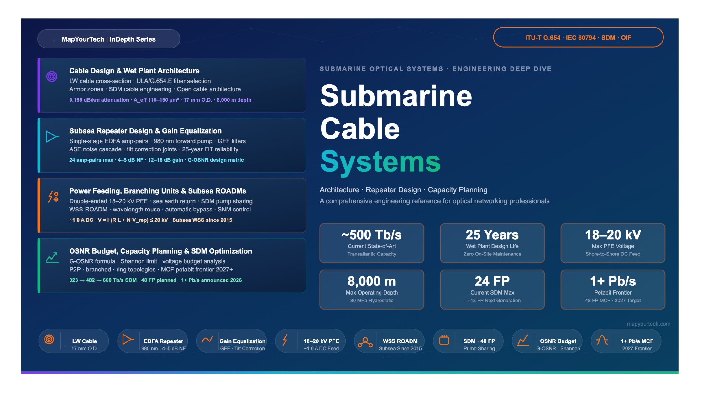

Submarine Cable Systems: Architecture, Repeater Design, and Capacity Planning
A comprehensive engineering reference covering the full technology stack of modern subsea optical communication systems — from physical cable construction through EDFA-based repeater design, SDM-driven capacity scaling, and network topology planning.
Introduction
Submarine cable systems form the invisible foundation of the global internet. More than 97% of all international data traffic crosses the ocean floor over fiber-optic cables, making subsea infrastructure the critical enabler of modern digital commerce, communication, cloud computing, and international financial markets.
The engineering challenge of transoceanic optical transmission is unlike anything in terrestrial networks. A system spanning 10,000 km or more must deliver hundreds of terabits per second of capacity with exceptional reliability — and it must do so using submerged equipment that cannot be accessed for maintenance without a specialized cable ship and weeks of expensive marine operations. These constraints produce a design philosophy fundamentally different from terrestrial network practice: components are simplified to minimize failure modes, amplifiers are engineered for 25-year operational lifetimes at depths of up to 8,000 meters, and system margins are calculated with extreme conservatism to account for all phases of the cable lifecycle from manufacture through deployment, operation, repair, and eventual decommissioning.
The demand driving submarine systems has been relentless. Transatlantic capacity grew from approximately 52 Tb/s in 2015 to approximately 500 Tb/s by 2023 — nearly a tenfold increase in under a decade. This trajectory has forced the industry through a profound strategic transition. After years of maximizing spectral efficiency per fiber pair through advances in coherent modulation formats and digital signal processing (DSP), the approach is now bounded by practical limits approaching Shannon capacity. The industry has shifted its focus to Space Division Multiplexing (SDM): scaling total cable capacity by increasing the number of spatial channels — more fiber pairs per cable, additional spectral bands, and eventually multicore fiber — rather than extracting more from individual channels.
This article provides a research-grade treatment of submarine cable systems that covers the complete engineering stack. It begins with the historical context that shaped current system architectures, proceeds through the physical cable construction and fiber selection, then covers repeater optical design and gain equalization in depth, addresses power feeding system engineering, analyzes network topology options including branching units and subsea ROADMs, and culminates in the mathematical framework for capacity planning and the engineering of SDM systems at the capacity frontier. The article draws on published technical data from the latest generation of deployed systems and ongoing research to present the state of the field as of the mid-2020s.
Historical Evolution of Submarine Cable Systems
The history of submarine communications cables spans more than 160 years, beginning with the first transatlantic telegraph cable in 1858. While that early cable failed after only a few weeks of service, it demonstrated the feasibility of intercontinental connectivity and launched an industry that would transform global communication. The evolution from copper telegraph cables to modern fiber-optic systems with hundreds of terabits per second of capacity represents one of the most extraordinary engineering progressions in history.
2.1 Coaxial and Regenerative Systems
Practical submarine telephone cables using coaxial construction and vacuum tube amplifiers entered service with the TAT-1 system between North America and Europe in 1956. The essential architecture that emerged — cable, submerged amplifiers spaced at regular intervals, and terminal stations — has remained structurally stable through all subsequent technology generations, even as the underlying physics has transformed completely. These early systems used 3R regenerators (Regeneration, Re-shaping, Re-timing) that converted signals back to electrical form at each repeater before retransmitting. This provided excellent noise performance on a per-span basis, but it severely limited scalability: each regenerator supported only a single channel, and wavelength multiplexing was impossible. Capacity growth required more cables or more fiber pairs, each requiring a complete regeneration chain.
2.2 The EDFA Revolution
The invention and commercialization of the Erbium-Doped Fiber Amplifier (EDFA) in the late 1980s was the pivotal event in submarine systems engineering. The EDFA amplifies optical signals directly, without any optical-to-electrical-to-optical (OEO) conversion, over a broad wavelength range from approximately 1,525 to 1,568 nm (the C-band). Two capabilities made this transformational for submarine systems.
First, it enabled all WDM channels in the C-band to be amplified simultaneously with a single amplifier, eliminating the need for per-channel regenerators and dramatically reducing repeater cost per bit. Second, it freed system design from the hard channel-count ceiling of regenerative architectures. A single EDFA with sufficient gain could amplify 40, 80, or more WDM channels simultaneously — limited primarily by the accumulated amplified spontaneous emission (ASE) noise and the optical signal-to-noise ratio (OSNR) at the terminal receiver, not by repeater architecture. The TAT-12/13 systems commissioned in 1996 were among the first major transoceanic deployments using EDFA amplification at scale, delivering approximately 120 Gb/s on two fiber pairs — a dramatic leap over the preceding coaxial technology.
2.3 The Coherent Era
The introduction of coherent optical modulation into submarine systems around 2008–2010 constituted the second major architectural revolution. Coherent systems modulate both the amplitude and phase of the optical carrier and use polarization multiplexing to double the information density per channel. Combined with soft-decision forward error correction (SD-FEC), this delivered 100 Gb/s per WDM channel over transoceanic distances with substantially improved OSNR tolerance compared to direct-detection systems.
A critical secondary consequence was that dispersion compensation could be moved entirely into the DSP within the terminal equipment. This eliminated the need for Dispersion Compensating Fiber (DCF) modules distributed throughout the link — modules that added significant insertion loss, reducing the power budget available for signal amplification. Without inline DCF requirements, cable designs could optimize purely for low attenuation and large effective area rather than managing dispersion characteristics across the entire link. This architectural decoupling also enabled the "open cable" model: the physical wet plant could be specified and deployed by one vendor or consortium, while SLTE equipment from any compatible vendor could operate over the cable without requiring end-to-end joint optimization of the transmitter and the optical path.
Figure 1: Approximate capacity milestones for representative submarine cable systems, updated through 2026. Values represent total design capacities; actual operating capacities vary by lit equipment. 2025–2026 entries reflect announced design targets. IOEMA North Sea and Meta global cable figures represent announced targets for systems targeting 2027+ readiness.
2.4 The SDM Transition
By the early 2020s, the industry confronted a structural limit on per-fiber-pair capacity. Coherent modulation formats were approaching the Shannon spectral efficiency limit for the available OSNR margin determined by the fiber attenuation, effective area, and amplifier noise figure. The only path to sustained capacity growth was to multiply the number of independent spatial channels within the cable.
Space Division Multiplexing in submarine systems encompasses three complementary approaches. The most immediate is increasing fiber pair count: from the 4–8 fiber pairs typical of early DWDM systems to the 16–24 fiber pairs of current-generation cables and eventually 48 or more. The second approach is spectral band expansion: deploying amplifiers covering both the C-band and L-band to double the available WDM bandwidth per fiber pair. Only one transoceanic C+L system — the Pacific Light Cable Network (PLCN) — had been deployed as of 2024, highlighting the complexity of L-band subsea amplification. The third approach, currently in research and early deployment, is multicore fiber, where a single fiber strand carries multiple independent cores, each functioning as an independent transmission channel.
The industry's SDM focus has profoundly changed the optimization landscape. A purely per-fiber-pair approach maximizes OSNR margin and spectral efficiency. An SDM approach trades some per-fiber-pair performance to enable more fiber pairs within the same power budget, achieving higher total cable capacity even as individual fiber pair performance may be somewhat reduced. This trade-off, governed by pump sharing techniques in the repeater design, is central to modern submarine system engineering and is analyzed in depth in Sections 5 and 7.
- Submarine cable systems have evolved through three major technology eras: coaxial/regenerative (1956–1990s), EDFA-amplified WDM (1996–2010), and coherent SDM (2010–present).
- EDFA amplification enabled WDM and eliminated per-channel 3R regeneration, transforming capacity economics by allowing a single amplifier to serve all WDM channels simultaneously.
- Coherent detection moved dispersion compensation entirely into DSP, enabling large effective area fiber designs and the open cable architecture where wet plant and dry plant are decoupled.
- The SDM transition shifts system optimization from per-fiber-pair spectral efficiency to total cable capacity per unit of power budget, driving fiber pair counts from 4–8 toward 24–48 and beyond.
Read the Full Analysis with Premium
The remaining 89% of this article — the design numbers, trade-offs and field guidance — is part of MapYourTech Premium, along with the full premium library, courses and professional tools.


