
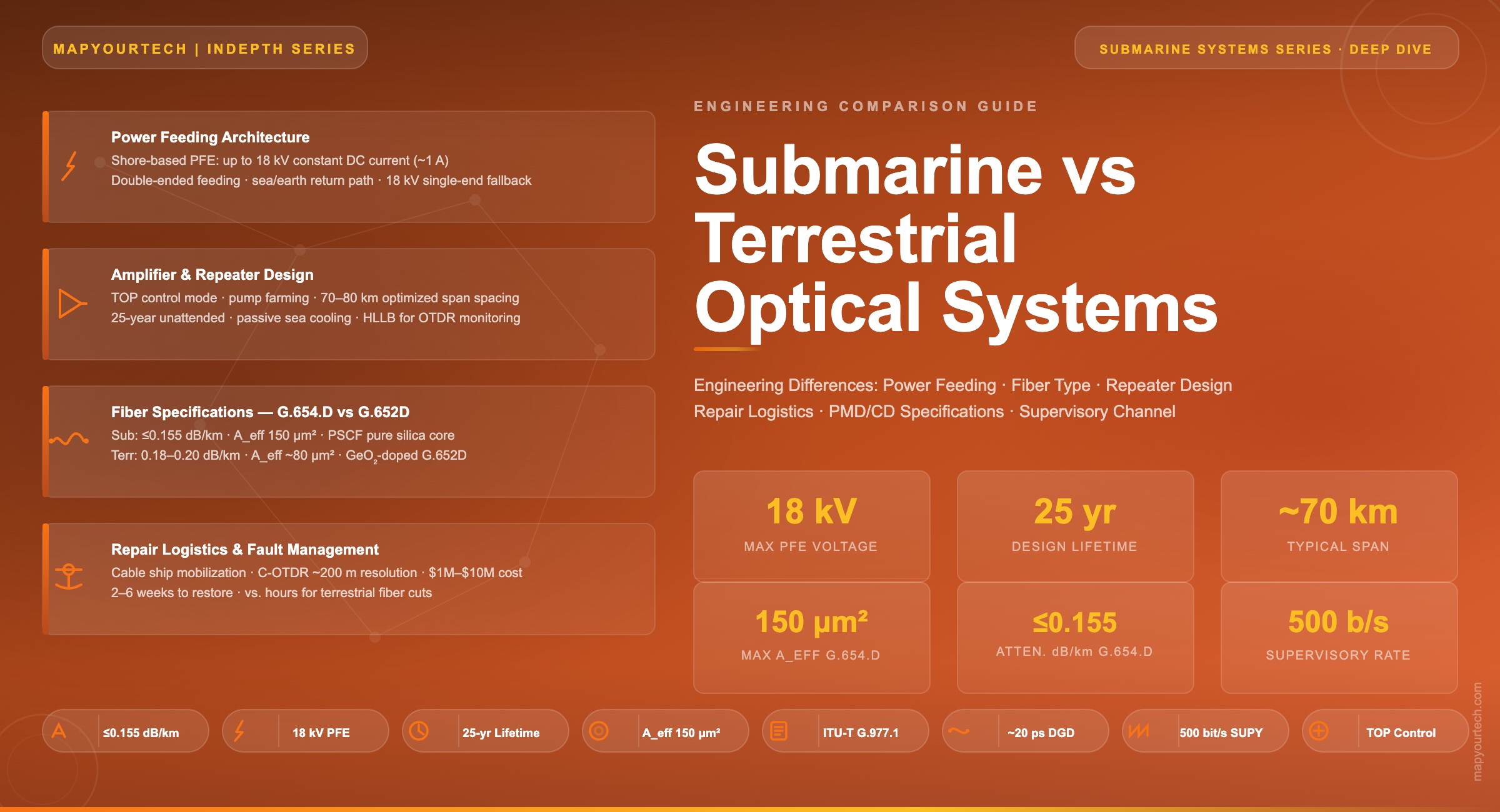

Submarine vs Terrestrial Optical Systems: Engineering Differences
A systematic engineering comparison of power feeding architectures, amplifier spacing constraints, fiber selection, system lifetime design, repair logistics, PMD/CD specifications, and supervisory channel design across both system classes
Main Points
- Submarine systems require specialized DC power feeding (up to 18 kV, ~1 A) from shore stations over thousands of kilometres — a constraint with no terrestrial equivalent.
- Repeater spacing in submarine systems (50–80 km typical) is dictated by power budget and sea depth, not just optical loss, unlike terrestrial spans of 40–120 km with simple rack-mounted amplifiers.
- Submarine fiber (ITU-T G.654, Aeff 110–150 μm²) is optimized for ultra-low attenuation and large effective area; terrestrial deployments predominantly use G.652D.
- Submarine systems are designed for a 25-year unattended lifetime; terrestrial equipment is engineered for 15 years with accessible field maintenance.
- A single submarine cable repair requires a specialized cable ship, weeks at sea, and costs millions of dollars — making fault prevention and the supervisory monitoring system engineering disciplines in their own right.
1. Introduction and System Context
Optical fiber transmission systems fall into two broad engineering families whose surface similarities — DWDM, EDFA amplification, coherent modulation — mask profoundly different design philosophies. Terrestrial optical systems are engineered around the premise of accessibility: racks are swapped, amplifiers are upgraded, spans are re-engineered. Submarine systems are engineered around the opposite premise: that once a component sinks to the ocean floor, reaching it costs millions of dollars and weeks of specialized ship time. Every engineering decision in a submarine system is shaped by that single, immovable constraint.
This article examines the engineering differences between the two families across seven principal dimensions: power feeding, amplifier spacing and repeater design, fiber type selection, system lifetime requirements, repair logistics, polarization mode dispersion (PMD) and chromatic dispersion (CD) management, and supervisory channel architecture. The treatment is directed at senior engineers and system architects who understand both system classes and seek a rigorous, quantitative comparison drawn from current industry standards and deployment practice.
An important structural distinction exists within the submarine family itself: unrepeatered and repeatered systems. Unrepeatered systems, typically extending to 300–600 km, carry no active submerged equipment and can share many engineering assumptions with long-haul terrestrial networks — high-count fiber cables, standard management interfaces, and accessible end-point equipment. Repeatered systems — the focus of this article — insert active amplifiers (repeaters) at regular intervals along thousands of kilometres of cable and constitute a genuinely distinct engineering discipline. The physical and economic consequences of placing amplifiers on the seabed at depths reaching 8,000 m drive nearly every specification difference discussed here.
2. Historical Context and Evolution
The divergence between submarine and terrestrial optical engineering has roots that predate fiber optics entirely. Coaxial submarine telegraph and telephone cables established the fundamental power-feeding model — shore-based DC supplies energizing repeaters in series via the cable conductor — by the 1950s. When fiber optics replaced coaxial transmission, the power-feeding architecture remained unchanged because no viable alternative existed: powering equipment at the bottom of the Pacific Ocean from the shore is the only option.
The first transatlantic fiber submarine cable, TAT-8, entered service in 1988 at 280 Mbit/s using direct detection and regenerative repeaters. It established the 25-year design lifetime convention that persists today. Terrestrial long-haul systems of the same era were already being upgraded and replaced on much shorter cycles as technology advanced.
The 1993 introduction of optical amplifier repeaters — replacing regenerative 3R repeaters (re-amplification, re-shaping, re-timing) — was a watershed event. Erbium-doped fiber amplifiers (EDFAs) in the repeater body provided wavelength-transparent amplification, but they also raised the power feeding current requirements as wavelength-division multiplexing (WDM) channel counts grew. By the year 2000, transpacific systems operated at 8 kV maximum PFE voltage. As of 2026, enhanced PFEs can generate 18 kV, enabling single-end feeding of the entire cable in fault scenarios.
In terrestrial networks, the same period saw EDFA technology evolve from specialized laboratory equipment to commodity modules mounted in standard 19-inch racks, powered from −48 VDC station supplies, field-replaceable in minutes. The engineering cultures of the two industries — submarine vendors with 100+ year histories, terrestrial equipment vendors on 18-month product cycles — reinforced the technical divergence.
The coherent technology revolution, which arrived in terrestrial networks around 2010–2012 and in submarine systems shortly after, created a new shared foundation. Both system families now deploy polarization-multiplexed quadrature phase-shift keying (PM-QPSK), higher-order quadrature amplitude modulation (QAM), and probabilistic constellation shaping (PCS). But the physical layer constraints imposed by power budget, fiber choice, and amplifier architecture differ enough that submarine-grade coherent transceivers remain distinct product lines from their terrestrial counterparts.
Section 2 — Main Points
- The submarine power-feeding model (shore-to-sea DC) was inherited from coaxial cable era and remains architecturally unchanged.
- The 25-year design lifetime convention was established by TAT-8 in 1988 and persists in all current submarine specifications.
- EDFA repeaters (1993) enabled WDM but simultaneously raised power budget complexity unique to submarine systems.
- Coherent technology created a shared signal processing foundation, but submarine-grade transceivers retain distinct physical layer specifications.
3. Fundamental System Architecture Differences
The most direct way to frame the engineering divergence is through the distinction between wet plant and dry plant in submarine systems — a distinction with no direct terrestrial analogue. In submarine networks, equipment divides sharply between the dry plant (everything inside climate-controlled stations: terminal transmission equipment, power feeding equipment, network management systems) and the wet plant (everything on the ocean floor: repeaters, branching units, reconfigurable optical add-drop multiplexer (ROADM) nodes, and the cable itself).
Wet plant components are engineered around a single overriding principle: they must function reliably for 25 years without human intervention. No field replacement. No firmware update that requires a reboot with risk of failure. No module swap. This constraint propagates through every engineering specification: component selection, redundancy architecture, thermal management, mechanical housing design, and power supply configuration.
Submarine System Characteristics
- Wet plant (active deep-sea equipment) + dry plant (shore stations)
- Power supplied via cable conductor from shore (up to 18 kV DC, ~1 A)
- Repeaters at 50–80 km spacing, 25-year unattended life
- Up to 16 fiber pairs per cable (SDM era)
- Separate network management for wet plant (supervisory over fiber)
- Repair requires specialized cable ship: days to weeks
- Fiber: G.654, Aeff 80–150 μm², attenuation ≤0.15 dB/km
- Designed for 6,000–20,000+ km system lengths
Read the Full Analysis with Premium
The remaining 88% of this article — the design numbers, trade-offs and field guidance — is part of MapYourTech Premium, along with the full premium library, courses and professional tools.



Course Title
Course description and key highlights
Course Content
Course Details
Celebrating 1,000+ LinkedIn posts
3 hours of Premium Pro, free
The full Premium Pro library, unlocked with one click. The clock starts the moment you check out and runs for 3 full hours - pick a time when you can make the most of it.
- Courses
- Interview preparation content
- Career development posts
- Simulators
- Calculators
- Market research
No card, nothing to cancel. One pass per person. Sign in or create a free account at checkout.
Follow MapYourTech on LinkedIn for regular updates and future promos.
New articles, tool releases and member offers, posted as they go live.
Follow MapYourTech on LinkedIn
Enjoying MapYourTech? Follow us on LinkedIn. One click and this stops appearing.
- New technical articles and tool releases, posted as they go live
- Course launches and member offers before they reach the site
- Standards and industry updates worth an optical engineer's time
New articles, tool releases and member offers, posted as they go live.