
Probabilistic Constellation Shaping in Coherent Optical Transmission
The Maxwell-Boltzmann distribution, the probabilistic amplitude shaping architecture, the distribution matcher families, the standardized 800G shaped modes, and the published long-haul and submarine results — with the entropy, shaping gain and OSNR arithmetic carried through to numbers.
Higher-order modulation adds capacity and subtracts reach.
1. Introduction
A coherent transponder provisioned for 800 Gb/s in a 150 GHz slot has one degree of freedom left once the symbol rate, the constellation and the FEC code are fixed: how often each constellation point is transmitted. Uniform quadrature amplitude modulation spends that degree of freedom on nothing. Every point is equiprobable, the four outermost points of a 64QAM grid are sent as often as the four points nearest the origin, and the average symbol energy is higher than the delivered information rate requires. That surplus energy is charged to the receiver as additional required signal-to-noise ratio, and to the line system as launch power and nonlinear interference.
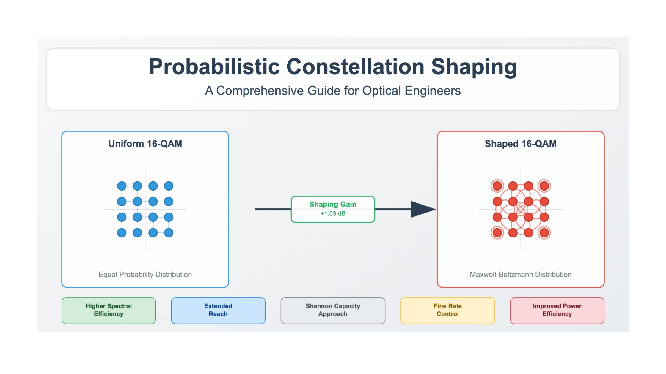
Probabilistic constellation shaping (PCS) removes that waste by transmitting inner points more often than outer ones. The constellation grid does not move; only the probability assigned to each point changes. Because the average energy falls while the grid spacing stays the same, the same information rate is delivered at lower signal-to-noise ratio, and the achievable rate of the shaped constellation tracks the Shannon bound far more closely than the uniform one does. The bound on that improvement is exactly 1.53 dB, the ratio πe/6 expressed in decibels (theoretical limit), and practical shaped modes in deployed coherent systems recover roughly half to three quarters of it.
The second consequence matters as much as the first. Entropy is a continuous quantity, so a shaped transmitter delivers fractional bits per symbol (3.61, 4.40, 5.35) where a uniform format offers only the integer steps 2, 3, 4, 5 and 6. A route that has 1.4 dB more optical signal-to-noise ratio than 16QAM needs but 5 dB less than 64QAM needs is stranded with uniform signalling; it runs 16QAM and leaves the margin unused. With shaping it runs at the entropy the margin supports. That is why shaping sits alongside baud rate, modulation order and FEC as one of the four levers a modem generation can pull.
This article covers the shaped distribution itself, the transmitter and receiver architecture that produces and undoes it, the distribution matcher families that differ in rate loss and complexity, the behaviour of shaped signals on the nonlinear fiber channel, the interoperable shaped modes now specified for 800G coherent interfaces, and the published results from long-haul and submarine plant. Vendor-proprietary shaping schemes are named only where a public specification describes them.
2. Shaped Constellation Definition and Component Terms
A probabilistically shaped constellation is a fixed, uniformly spaced grid of M quadrature amplitude modulation points transmitted with unequal probabilities, chosen so that low-energy inner points occur more often than high-energy outer points. The information rate such a constellation carries is the entropy of that probability distribution, expressed in bits per symbol per polarisation, and it is always lower than log2 M.
2.1 Distinctions From the Adjacent Quantities
Three quantities are conflated more often than any others in shaping discussions, and Fig. 1 separates them on purpose. Constellation order M is the number of points the digital-to-analogue converter and the demapper must address; it sets hardware complexity and nothing else. Entropy H(X) is the information the symbol stream carries, and it is the number that enters every rate and capacity calculation. The uniform bit count log2 M is the ceiling that entropy approaches when shaping is switched off, not a rate the shaped mode delivers. A mode described as PCS-64QAM at 5.00 bits per symbol per polarisation addresses 64 points and carries five bits, and quoting it as a 64QAM mode overstates its rate by 20%.
Read the Full Analysis with Premium
The remaining 88% of this article — the design numbers, trade-offs and field guidance — is part of MapYourTech Premium, along with the full premium library, courses and professional tools.
You May Also Like

-
Free
-
September 4, 2026

-
Premium
-
September 4, 2026

-
Premium
-
September 4, 2026