
Few analogies proving the subject:-
- If the distance is to short and the attenuator is too close to the transmitter, the reflected light off the attenuator will be directed back towards the Tx laser. Which will also blow your transmitter.so we place it at Rx.
- Also keeping attenuator at Rx will attenuate the noise along with the signal.
- The most important reason for putting them on the RX side is that you are protecting that which needs to be protected – the receiver in your optics. This way you know that you’re not going to potentially blow the receiver in your optics by plugging in too large a signal because you assumed there was an attenuator on the TX at the far end, and there wasn’t.
- It’s more convenient to test the receiver power before and after attenuation or while adjusting it with your power meter at the receiver, plus any reflectance will be attenuated on its path back to the source.
Keynote on Using Attenuators With Fiber Optic Data Links
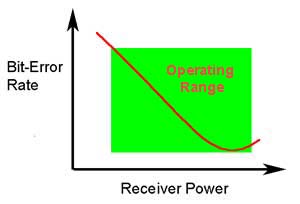
The ability of any fiber optic system to transmit data ultimately depends on the optical power at the receiver as shown above, which shows the data link bit error rate as a function of optical power at the receiver. (BER is the inverse of signal-to-noise ratio, e.g. high BER means poor signal to noise ratio.) Either too little or too much power will cause high bit error rates.
Too much power, and the receiver amplifier saturates, too little and noise becomes a problem as it interferes with the signal. This receiver power depends on two basic factors: how much power is launched into the fiber by the transmitter and how much is lost by attenuation in the optical fiber cable plant that connects the transmitter and receiver.
If the power is too high as it often is in short singlemode systems with laser transmitters, you can reduce receiver power with an attenuator. Attenuators can be made by introducing an end gap between two fibers (gap loss), angular or lateral misalignment, poor fusion splicing (deliberately), inserting a neutral density filter or even stressing the fiber (usually by a serpentine holder or a mandrel wrap). Attenuators are available in models with variable attenuation or with fixed values from a few dB to 20 dB or more.
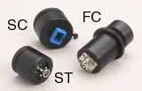
Gap-loss attenuators for multimode fiber
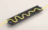
Serpentine attenuators for singlemode fiber
Generally, multimode systems do not need attenuators. Multimode sources, even VCSELs, rarely have enough power output to saturate receivers. Singlemode systems, especially short links, often have too much power and need attenuators.
For a singlemode applications, especially analog CATV systems, the most important specification, after the correct loss value, is return loss or reflectance! Many types of attenuators (especially gap loss types) suffer from high reflectance, so they can adversely affect transmitters just like highly reflective connectors.
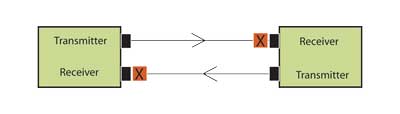
Choose a type of attenuator with good reflectance specifications and always install the attenuator ( X in the drawing) as shown at the receiver end of the link. This is because it’s more convenient to test the receiver power before and after attenuation or while adjusting it with your power meter at the receiver, plus any reflectance will be attenuated on its path back to the source.

Test the system power with the transmitter turned on and the attenuator installed at the receiver using a fiber optic power meter set to the system operating wavelength. Check to see the power is within the specified range for the receiver.
If the appropriate attenuator is not available, simply coil some patchcord around a pencil while measuring power with your fiber optic power meter, adding turns until the power is in the right range. Tape the coil and your system should work. This type of attenuator has no reflectance and is very low cost! The fiber/cable manufacturers may worry about the relaibility of a cable subjected to such a small bend radius. You should probably replace it with another type of attenuator at some point, however.
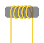
Singlemode attenuator made by wrapping fiber or simplex cable around a small mandrel. This will not work well with bend-insensitive fiber.
ref:http://www.thefoa.org/tech/ref/appln/attenuators.h


