Network Protection in Optical Network Architecture
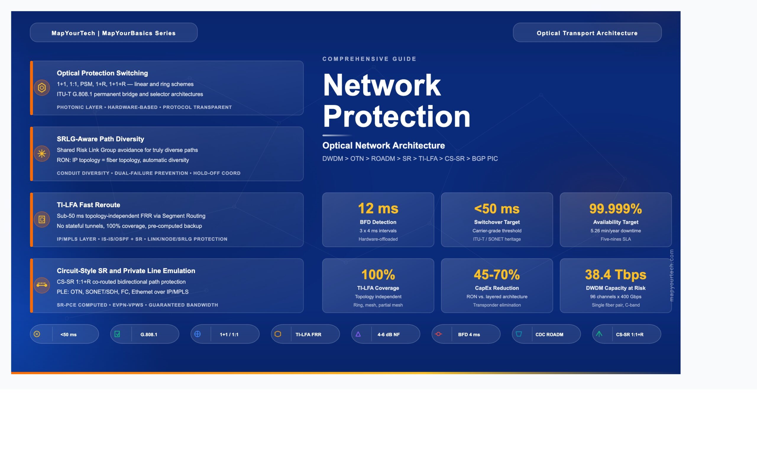
A deep engineering guide to protection switching, restoration mechanisms, and resilience strategies across DWDM, OTN, and converged IP-optical networks — from traditional 1+1 schemes to modern TI-LFA and IP-based protection.
1. Introduction
Network protection in optical network architecture refers to the set of mechanisms, protocols, and design strategies that ensure traffic continuity when physical or logical failures occur in an optical transport network. These mechanisms range from dedicated hardware-level optical switching (such as 1+1 and 1:1 path protection) to software-driven IP-layer techniques (such as Topology-Independent Loop-Free Alternate, or TI-LFA) that reroute traffic in under 50 milliseconds.
The telecommunications industry demands carrier-grade availability, typically expressed as 99.999% uptime, which allows no more than approximately 5.26 minutes of unplanned downtime per year. Achieving this target requires protection at multiple layers of the network: the fiber/optical layer, the Optical Transport Network (OTN) layer, and the IP/MPLS packet layer. Each layer offers distinct protection trade-offs in terms of switching speed, capacity efficiency, operational complexity, and cost.
This guide covers the full spectrum of optical network protection, from legacy SONET/SDH ring architectures through modern Routed Optical Networking (RON) designs. It explains the engineering rationale behind each protection scheme, provides real-world deployment scenarios, and examines how the convergence of IP and optical layers is transforming protection architecture. The standards foundation rests on ITU-T G.808 series (generic protection switching), ITU-T G.873.1 (OTN linear protection), and IETF Segment Routing specifications.
2. Why Network Protection is Needed
Optical fiber networks face a broad range of failure scenarios that make protection mechanisms essential. Fiber cuts from construction activities, natural disasters, and equipment aging represent the most common physical failures. A single fiber cut on a Dense Wavelength Division Multiplexing (DWDM) system carrying 96 channels at 400 Gbps per channel disrupts up to 38.4 Tbps of aggregate traffic. Without automatic protection, restoration of this capacity requires manual intervention that can take hours or even days.
Before comprehensive protection schemes existed, optical networks relied on spare fiber routes and manual patching. This approach resulted in restoration times measured in hours, with service level agreement (SLA) violations for every affected customer. The financial impact of network outages is significant: major service providers estimate that a single minute of core network downtime costs between $5,000 and $100,000, depending on the services affected.
Equipment failures add another dimension of risk. Optical amplifiers, transponders, and Reconfigurable Optical Add-Drop Multiplexers (ROADMs) all have finite mean time between failures (MTBF). A typical Erbium-Doped Fiber Amplifier (EDFA) has an MTBF of approximately 200,000 to 500,000 hours, but in a network with hundreds of amplifiers, at least one failure per year becomes statistically expected. The cumulative effect of these failure modes demands systematic, automated protection at every network layer.
Legacy multi-layer architectures introduced additional complexity. In a traditional three-layer design (IP/MPLS, OTN, and DWDM), protection was often deployed at each layer independently. A 50 Gbps traffic demand might require 100 Gbps at the IP layer (2x overbooking factor), 200 Gbps after link/path redundancy, and 400 Gbps after 1:1 optical layer protection. This cascade of redundancy multiplied capacity requirements by a factor of 8, resulting in significant capital overinvestment.
3. Problems Network Protection Solves
Network protection addresses several distinct engineering challenges, each mapping to a specific category of protection mechanism.
3.1 Single Points of Failure in Linear Topologies
A point-to-point DWDM link with no protection has exactly one optical path. Any break in that path — whether fiber cut, amplifier failure, or transponder malfunction — results in complete service loss. The 1+1 protection scheme solves this by transmitting identical signals simultaneously over two diverse fiber paths. The receiver selects the better signal continuously, providing hitless switchover in under 50 ms with zero coordination protocol overhead.
3.2 Capacity Waste in Dedicated Protection
While 1+1 protection provides excellent recovery speed, it permanently consumes 100% additional capacity for the protection path. The 1:1 protection scheme addresses this waste by allowing the protection path to carry low-priority "extra traffic" during normal operation. When a failure occurs, this extra traffic is preempted and the protection path carries the high-priority working signal. This approach reduces effective capacity overhead from 100% to approximately 50–70%, depending on extra traffic utilization.
3.3 Ring Topology Vulnerability
DWDM ring networks face the challenge of maintaining connectivity when a span or node within the ring fails. Optical ring protection schemes (based on ITU-T G.808.2) address this by establishing bidirectional protection switching around the ring. Shared ring protection allows N working channels to share a single protection bandwidth, improving capacity efficiency compared to dedicated per-channel protection.
3.4 Shared Risk Link Group (SRLG) Exposure
In traditional multi-layer architectures, the IP topology differs from the underlying fiber topology. Multiple IP links may traverse the same fiber conduit without the IP layer being aware of this shared physical path. A single conduit cut then simultaneously disrupts what the IP layer believes are independent, diverse paths. SRLG-aware protection solves this by providing the IP layer with visibility into the physical fiber routing, enabling computation of truly diverse backup paths.
3.5 Multi-Layer Coordination Gaps
When optical protection and IP protection operate independently, failback after repair creates coordination problems. The optical layer may restore a repaired path while the IP layer has already converged onto an alternate route, leading to traffic oscillation or suboptimal routing. Converged IP-optical architectures solve this by centralizing protection decisions at the IP layer, which has full visibility of both logical and physical topologies.
4. Importance of Network Protection in Optical Architecture
Network protection occupies a central position in modern optical network design for both technical and business reasons. From a technical perspective, optical networks carry aggregated traffic from thousands of individual services. A single 400 Gbps wavelength may transport traffic for hundreds of enterprise customers, mobile backhaul connections, and content delivery streams. The blast radius of an unprotected failure is enormous.
Business-critical services demand strict SLAs. Financial trading networks require round-trip latency below 1 ms with availability above 99.999%. Healthcare telemedicine circuits carry real-time surgical guidance. Mobile 5G xHaul transport must maintain sub-50 ms failover to preserve baseband handover integrity. Each of these application domains requires a protection architecture matched to its specific recovery time objective (RTO).
The economic dimension is equally compelling. Deploying protection at the right layer reduces total cost of ownership (TCO). Duplicating protection across all three layers (IP, OTN, and DWDM) multiplies capacity requirements by 4× to 8×. A well-designed single-layer protection strategy, where protection responsibility is assigned to the most efficient layer for each service type, can reduce protection overhead to 1.5× to 2× while maintaining the same availability targets.
In converged architectures such as Routed Optical Networking (RON), the IP layer assumes protection responsibility for packet services, while circuit-style protection (CS-SR with 1:1 path protection) handles private line services. This eliminates the redundant protection at the optical layer, reducing CapEx by 45% to 70% and power consumption by 60% to 75% compared to traditional transponder-based architectures.
5. Evolution of Network Protection
The evolution of network protection mirrors the broader transformation of transport networks from circuit-switched TDM systems to packet-based, software-defined architectures.
5.1 SONET/SDH Era (1990s–2000s)
Synchronous Optical Networking (SONET) and Synchronous Digital Hierarchy (SDH) established the original 50 ms protection switching target through Automatic Protection Switching (APS) on ring topologies. Unidirectional Path Switched Ring (UPSR) and Bidirectional Line Switched Ring (BLSR) provided deterministic protection for TDM traffic. These mechanisms were elegant but rigid, designed for fixed-bandwidth circuit services in ring topologies with limited scalability to mesh networks.
5.2 OTN Protection (2000s–2010s)
The Optical Transport Network (OTN), standardized in ITU-T G.709, introduced sub-network connection protection (SNCP) at the Optical Data Unit (ODUk) level. OTN protection provided sub-50 ms electrical switching with tandem connection monitoring (TCM) for fault localization. The ITU-T G.873.1 recommendation defined linear protection schemes including ODUk SNC with inherent monitoring (SNC/I), non-intrusive monitoring (SNC/N), and sublayer monitoring (SNC/S). These schemes allowed protection within and across administrative domains.
5.3 DWDM Optical Layer Protection (2000s–Present)
DWDM networks introduced optical layer protection through dedicated fiber pairs and ROADM-based restoration. Protection schemes included 1+1 (dedicated protection with permanent bridge), 1:1 (dedicated with extra traffic), 1+R (protection with optical restoration), and 1+1+R (dedicated protection plus restoration for dual-failure scenarios). Colorless, Directionless, and Contentionless (CDC) ROADM technology enabled dynamic optical restoration by allowing transponders to retune to any available wavelength on any ROADM degree — a major advance over fixed, colored, directional add/drop ports.
5.4 IP-Layer Protection and Convergence (2015–Present)
The introduction of Segment Routing (SR) with Topology-Independent Loop-Free Alternate (TI-LFA) moved protection intelligence to the IP layer. TI-LFA provides sub-50 ms Fast Reroute (FRR) protection for link, node, and SRLG failures without requiring stateful tunnels. Combined with 400G coherent pluggable optics (400ZR/OpenZR+) that place DWDM interfaces directly on routers, this approach enables Routed Optical Networking — a converged architecture that collapses three network layers into one, with IP taking responsibility for both switching and protection.
6. Core Concepts and Fundamentals
6.1 Protection vs. Restoration
Protection refers to pre-provisioned backup resources that are ready to carry traffic immediately upon failure detection. The backup path, bandwidth, and switching mechanism are all configured before any failure occurs. Protection switching operates in under 50 ms because no path computation is required at failure time. Examples include 1+1 and 1:1 schemes defined in ITU-T G.808.1.
Restoration refers to the dynamic computation and activation of backup paths after a failure is detected. Restoration requires a control plane (such as GMPLS, WSON, or SSON) to discover available resources, compute a new path, and signal the cross-connects along that path. Restoration times range from hundreds of milliseconds to several seconds, depending on network complexity and control plane speed. The "R" in schemes like 1+R and 1+1+R denotes this restoration capability.
6.2 Protection Switching Architectures
ITU-T G.808.1 defines two fundamental bridge architectures. In a permanent bridge (1+1), the signal is continuously bridged onto both working and protection transport entities at the source. The selector at the sink chooses the better signal. This architecture requires no Automatic Protection Switching (APS) protocol because both paths always carry traffic. In a selector bridge (1:1, 1:N), only the working path carries traffic during normal operation. Upon failure detection, an APS protocol coordinates switching at both ends to move traffic to the protection path.
6.3 Failure Detection Mechanisms
Fast failure detection is the first step in any protection switching sequence. At the optical layer, Loss of Signal (LoS) and Loss of Frame (LoF) can be detected in approximately 10 ms. Bidirectional Forwarding Detection (BFD) at the IP layer provides detection in as little as 12 ms (3 × 4 ms intervals) with hardware offload. OTN provides in-band monitoring through Trail Trace Identifier (TTI) and Tandem Connection Monitoring (TCM) overhead bytes, enabling fault localization across administrative boundaries.
6.4 Switching Speed Budget
The 50 ms protection target budget is allocated across detection, hold-off, switching, and signal recovery phases.
Ttotal = Tdetect + Tholdoff + Tswitch + Trecovery ≤ 50 ms

Where:
  Tdetect   = Failure detection time (LoS ~10 ms, BFD ~12 ms)
  Tholdoff  = Hold-off timer to allow lower-layer protection first (0–10,000 ms, configurable)
  Tswitch   = APS protocol exchange and cross-connect activation (~5–20 ms)
  Trecovery = Signal reacquisition at receiver (laser retuning ~1–5 ms)
Practical Example: In a 1+1 optical protection scheme with permanent bridge, Tdetect = 10 ms (optical LoS), Tholdoff = 0 ms (no coordination needed), Tswitch = 0 ms (selector-only, no APS), Trecovery = 0 ms (signal already present on protection path). Total switchover time: approximately 10 ms — well within the 50 ms target.
6.5 Shared Risk Link Group (SRLG)
An SRLG identifies a set of network links that share a common physical resource, such as a fiber conduit, a duct, or a bridge crossing. If any element of that shared resource fails, all links in the SRLG fail simultaneously. SRLG information is essential for computing truly diverse protection paths. In traditional architectures, the IP layer has no visibility into the optical fiber topology, so wavelength planning must manually prevent SRLG conflicts. In converged RON architectures, the IP topology equals the fiber topology, making SRLG avoidance automatic through standard IGP shortest-path computation with disjoint constraints.
Takeaway: Protection pre-provisions backup resources for sub-50 ms switchover, while restoration dynamically computes paths in seconds. The 50 ms budget spans detection, hold-off, switching, and signal recovery. SRLG awareness ensures that backup paths are genuinely diverse at the physical layer, preventing correlated dual failures from defeating protection.
7. Architecture of Network Protection in Optical Networks
Network protection in optical architectures operates across multiple functional layers, each with distinct mechanisms and trade-offs. Understanding the full architecture requires examining protection at the optical physical layer, the OTN switching layer, and the IP/MPLS packet layer — as well as the interaction between these layers.
7.1 Diagram Components Explained
Router (PE/P)
What it is: A Provider Edge (PE) or Provider (P) router at the IP/MPLS layer. PE routers connect to customer equipment and originate/terminate services. P routers provide transit forwarding.
What it does: Executes IGP (IS-IS or OSPF) with Segment Routing extensions to compute primary and backup paths. Installs TI-LFA backup paths in the Forwarding Information Base (FIB) before any failure occurs. On detecting a link failure (via BFD in 12 ms or optical LoS in 10 ms), the router switches to the pre-computed backup path in under 50 ms total.
Why it exists: Without routers performing IP-layer protection, every service would depend on optical-layer protection, which cannot distinguish between service priorities and does not coordinate failback with the packet network.
ROADM (Colorless, Directionless, Contentionless)
What it is: A Reconfigurable Optical Add-Drop Multiplexer equipped with Wavelength Selective Switch (WSS) technology that supports colorless (any wavelength on any port), directionless (any port to any degree), and contentionless (multiple instances of the same wavelength) add/drop.
What it does: Dynamically adds, drops, and routes optical wavelengths through the network. In protection scenarios, CDC ROADMs enable optical restoration by switching wavelengths to alternate fiber routes and retuning transponders to available frequencies — all without physical intervention. A typical CDC ROADM supports 2 to 16 line degrees and up to 96 wavelengths per degree on the C-band ITU-T grid.
Why it exists: Without CDC capability, changing a wavelength's direction or frequency after a failure required manual fiber patching. CDC ROADMs enable automated, software-controlled optical restoration (the "R" in 1+R and 1+1+R), reducing restoration time from hours to seconds.
In-Line Amplifier (ILA / EDFA)
What it is: An Erbium-Doped Fiber Amplifier placed along the fiber route to compensate for span loss. A typical ILA provides 15–25 dB of gain with a noise figure of 4–6 dB.
What it does: Amplifies all wavelengths in the C-band (or C+L-band) simultaneously without optical-to-electrical conversion. Modern ILAs include automatic power control (APC) and transient suppression to maintain stable channel power when wavelengths are added, dropped, or rerouted during protection events.
Why it exists: Fiber attenuation (approximately 0.18–0.20 dB/km on G.652D fiber) limits unamplified span distances to about 80–120 km. Without ILAs, protection paths over alternate, longer fiber routes would be infeasible due to insufficient optical power.
OTN Switch
What it is: An OTN cross-connect that switches traffic at the ODUk (Optical Data Unit) level. ODU0 carries 1.25 Gbps, ODU2 carries 10 Gbps, ODU4 carries 100 Gbps, and ODUCn carries N × 100 Gbps.
What it does: Provides sub-50 ms electrical switching between working and protection paths using the SNCP mechanism. OTN switches perform traffic grooming (aggregating lower-rate ODUs into higher-rate containers) and provide tandem connection monitoring (TCM) overhead for fault localization across up to 6 administrative domains.
Why it exists: OTN fills the gap between raw optical wavelength protection and IP packet protection. It provides deterministic, protocol-agnostic protection for sub-wavelength services (e.g., a 10 Gbps private line riding within a 100 Gbps wavelength) without requiring IP/MPLS awareness.
7.2 Hold-off Timer Coordination Across Layers
When a fiber failure occurs, every layer detects it. Without coordination, all three layers would attempt to switch traffic simultaneously, causing protection fights, traffic oscillation, and suboptimal routing. Hold-off timers solve this by enforcing a strict response hierarchy: lower layers act first; upper layers wait long enough for the layer below to attempt recovery. The diagram below shows the temporal cascade for a typical multi-layer deployment.
8. Implementation Details
8.1 Optical Layer Protection Implementation
The diagram below provides a consolidated visual reference for every protection scheme discussed in this section, showing the signal flow, switching behavior, and key trade-offs of each mechanism across both the optical and IP layers.
Optical layer protection operates at the wavelength or fiber level and requires no knowledge of the client signal format.
8.1.1 Protection Switching Module (PSM)
A PSM is a 1+1 optical protection device typically deployed at point-to-point DWDM terminals. It splits the transmit signal into two identical copies, sends them over diverse fiber paths, and selects the better received signal using optical power monitoring. PSM switching is triggered by loss of light and completes in under 10 ms. It requires no control plane or APS protocol. The trade-off is 100% capacity overhead: every protected wavelength consumes two fibers and two amplifier chains.
8.1.2 ROADM-Based Restoration (1+R)
When a CDC ROADM network detects a fiber cut, the embedded control plane (WSON or SSON) locates an alternate path and available wavelength, reconfigures WSS cross-connects along the new path, and retunes the endpoint transponders to the new wavelength. This "R" (restoration) mechanism provides protection without dedicating a permanent backup path. Restoration times range from 200 ms to several seconds depending on the number of ROADM hops and control plane latency. The benefit is N:1 capacity sharing: multiple working wavelengths can share a pool of restoration capacity across the mesh.
8.1.3 Combined 1+1+R
The most resilient optical scheme combines dedicated 1+1 protection with dynamic restoration. The 1+1 pair provides sub-50 ms recovery for the first failure. If the second fiber also fails (a dual-failure scenario), the ROADM restoration mechanism computes a third path. This scheme is common in submarine and long-haul networks where dual failures, though rare, have catastrophic consequences.
8.2 IP-Layer Protection Implementation
8.2.1 TI-LFA Fast Reroute
Topology-Independent Loop-Free Alternate (TI-LFA) is the recommended IP-layer protection mechanism for modern networks. It works within the Segment Routing (SR) framework and provides sub-50 ms FRR protection for link, node, and SRLG failures. TI-LFA operates as follows:
The IGP (IS-IS or OSPF with SR extensions) on each node computes the shortest path to every destination. Simultaneously, it computes a loop-free alternate path that follows the post-convergence route. When a node detects a link failure (via BFD or optical LoS), it immediately installs the pre-computed backup path using a short SID list (typically 1–3 segments). Traffic shifts to this backup path within 50 ms. Once the IGP reconverges (typically 300 ms to 1 second), the backup path is replaced by the newly computed optimal path.
TI-LFA provides 100% topology coverage regardless of network topology (ring, mesh, or partial mesh). It requires no stateful tunnels, no RSVP-TE, and no targeted LDP sessions. This simplicity is a major advantage over legacy MPLS-TE FRR, which required explicit tunnel provisioning for every protected path.
8.2.2 Circuit-Style Segment Routing (CS-SR)
For private line and wavelength services that require deterministic protection, CS-SR extends Segment Routing with circuit-style capabilities: co-routed bidirectional paths, control-plane-independent persistence, guaranteed bandwidth, and 1:1 end-to-end path protection with restoration. A CS-SR policy defines a working path (higher preference) and a protect path (lower preference), both computed by the SR Path Computation Element (SR-PCE) with disjointness constraints. Path integrity is monitored end-to-end, and protection switching occurs in under 50 ms when the working path fails.
8.2.3 BGP Prefix Independent Convergence (PIC)
BGP PIC provides fast convergence for services with BGP next-hops. It pre-programs backup paths in the FIB so that when an egress PE node or link fails, the ingress PE can switch to the backup PE in a prefix-independent manner. BGP PIC Edge Link Protection and BGP PIC Edge Node Protection together provide sub-second convergence for VPN services, complementing TI-LFA's underlay protection with overlay service protection.
9. Use Cases
9.1 Service Provider Core and Long-Haul
Service provider core networks carry aggregated traffic from millions of subscribers across distances of 500 to 5,000+ km. Protection is typically deployed as 1+1+R at the DWDM layer for wavelength services (providing sub-50 ms recovery for the first failure and seconds-scale restoration for dual failures) combined with TI-LFA at the IP layer for packet services. A typical deployment carries 80 to 96 wavelengths per fiber at 400 Gbps each, giving a total fiber capacity of 32 to 38.4 Tbps. The SRLG-aware design ensures that working and protection fibers traverse physically diverse conduits, often following different geographic routes entirely.
9.2 Metro and Regional Networks
Metro networks use ring or partial-mesh ROADM topologies with 2 to 8 degree nodes. Protection often uses a combination of 1+1 optical protection for high-priority wavelength services and IP-layer TI-LFA for aggregated packet traffic. CDC ROADM technology allows metro networks to implement shared mesh restoration across the ring, where a single protection bandwidth pool serves multiple working wavelengths. Typical metro spans are 40 to 120 km with EDFA amplification every 80 km.
9.3 Data Center Interconnect (DCI)
Data center interconnect demands very high bandwidth (typically 400 Gbps to multi-terabit) with low latency and fast protection. Modern DCI deployments use 400ZR or OpenZR+ coherent pluggables directly in data center switches, eliminating the need for external transponders. Protection is handled at the IP/Ethernet layer using ECMP (Equal-Cost Multi-Path) across multiple diverse DCI links. This approach provides sub-50 ms failover with efficient bandwidth utilization (all paths carry working traffic simultaneously).
9.4 Mobile 5G xHaul Transport
5G networks require sub-50 ms failover in the fronthaul (CPRI/eCPRI), midhaul, and backhaul segments to maintain radio baseband processing continuity. The converged IP transport architecture uses Segment Routing with TI-LFA end-to-end across access, aggregation, and core domains. SR-PCE (Path Computation Element) provides end-to-end path optimization with SLA awareness, while circuit-style SR delivers guaranteed bandwidth for precision timing (SyncE, PTP) distribution.
9.5 Private Line / Wavelength Services
Enterprise private line services demand high SLAs (99.999% availability, guaranteed bandwidth, sub-50 ms protection). In traditional architectures, OTN provides 1:1 or 1+1 protection at the ODUk level. In converged RON architectures, Circuit-Style Segment Routing (CS-SR) with Private Line Emulation (PLE) delivers these SLAs over an IP/MPLS network. PLE packetizes the client signal (OTN, SONET/SDH, Ethernet, or Fibre Channel), while CS-SR provides persistent, co-routed, bidirectional paths with 1:1+R end-to-end path protection and restoration.
10. Benefits
Carrier-Grade Availability: All protection schemes target the 50 ms switchover threshold, supporting 99.999% availability SLAs. TI-LFA achieves this target with 100% topology coverage regardless of network shape, while optical 1+1 achieves it with dedicated hardware.
Reduced Capital Investment: Moving protection responsibility to a single layer (IP for packet, CS-SR for circuits) eliminates the 4×–8× capacity multiplier of multi-layer protection. Real-world deployments report 45% to 70% CapEx reduction by eliminating transponder chassis and consolidating protection at the IP layer using coherent pluggable optics.
Operational Simplification: Converged protection reduces the number of management domains from three (DWDM NMS, OTN NMS, IP NMS) to one unified network controller. SRLG information flows automatically from the optical network to the IP layer via hierarchical controllers, eliminating manual SRLG database maintenance.
Efficient Bandwidth Utilization: IP-layer protection with ECMP allows all paths to carry working traffic simultaneously, achieving 100% link utilization during normal operation. Compared to optical 1+1 protection (which caps utilization at 50%), this represents a 2× improvement in bandwidth efficiency.
Multi-Failure Resilience: Combined protection and restoration schemes (1+1+R at the optical layer, or TI-LFA + CS-SR 1:1+R at the IP layer) provide recovery from dual and even triple failures, exceeding the resilience of any single protection mechanism.
11. Limitations and Challenges
Optical Protection Capacity Overhead: Dedicated 1+1 optical protection permanently consumes 100% additional fiber and amplifier capacity. In capacity-constrained networks, this overhead is prohibitively expensive. Shared protection (1:N) reduces this overhead but introduces contention risk when multiple working paths fail simultaneously.
ROADM Restoration Speed: Dynamic optical restoration through CDC ROADMs requires control plane signaling, WSS reconfiguration, and transponder retuning. Total restoration time ranges from 200 ms to 10+ seconds, which exceeds the 50 ms target for services requiring carrier-grade protection. ROADM restoration is better suited as a complement to dedicated protection (the "R" in 1+1+R) rather than a primary protection mechanism.
Cross-Layer Coordination Complexity: When protection operates at multiple layers simultaneously, uncoordinated switching can cause traffic oscillation, protection fights, and suboptimal routing. Hold-off timers partially address this but require careful tuning. A hold-off timer set too short causes the higher layer to interfere with lower-layer protection; set too long, it delays recovery.
IP Protection Skill Gap: Moving protection from the optical layer to the IP layer requires optical transport teams to develop IP/MPLS and Segment Routing expertise. The operational model shifts from configuring optical protection groups to managing IGP metrics, SR policies, and BFD parameters. This organizational transformation takes 12 to 24 months in typical service provider environments.
Loss-of-Light Switching Limitations: PSM-based optical protection relies on detecting loss of optical power. Failures that degrade signal quality (increased bit error rate due to fiber bending, connector contamination, or amplifier degradation) may not trigger loss-of-light detection, leaving the service on a degraded path until the fault exceeds the detection threshold.
12. Comparison with Alternatives
| Criterion | 1+1 Optical | 1:1 OTN (SNCP) | 1+1+R (ROADM) | TI-LFA (IP/SR) | CS-SR (IP Circuit) |
|---|---|---|---|---|---|
| Switchover Time | <10 ms | <50 ms | <50 ms (1+1) + seconds (R) | <50 ms | <50 ms |
| Capacity Overhead | 100% (dedicated) | 100% (but extra traffic allowed) | 100% + shared restore pool | 0% (ECMP, all paths used) | 100% (dedicated protect path) |
| Topology Coverage | Point-to-point only | End-to-end / per-link | Mesh (ROADM network) | 100% (topology independent) | End-to-end paths |
| Multi-Failure Support | No (2 paths only) | No (2 paths only) | Yes (R provides 3rd path) | Yes (multi-path via ECMP) | Yes (1:1+R, 3 candidate paths) |
| Protocol Awareness | None (bit-transparent) | OTN layer only | None (optical layer) | Full IP/MPLS awareness | Full IP + circuit emulation |
| SRLG Awareness | Manual fiber planning | Manual or GMPLS | WSON/SSON control plane | Automatic (congruent topology) | SR-PCE with disjoint constraints |
| Failback Coordination | Not coordinated with IP | Not coordinated with IP | Not coordinated with IP | Automatic (IGP reconvergence) | Controller-managed (SR-PCE) |
| Hardware Required | +1 trunk, PSM module | OTN switch fabric | CDC ROADM at each node | SR-capable routers only | SR-capable routers + SR-PCE |
| Best Fit | P2P metro DWDM | Sub-wavelength private lines | Long-haul, submarine | All packet services | Private line emulation over IP |
Takeaway: No single protection mechanism fits all scenarios. The most efficient approach combines TI-LFA for packet services (zero capacity overhead, full topology coverage) with CS-SR for circuit-style services (guaranteed bandwidth, deterministic paths). Pure optical protection (1+1, 1+1+R) remains essential for scenarios requiring protocol transparency or where IP infrastructure is not present.
13. Best Practices
13.1 Design Recommendations
Assign protection responsibility to the most efficient layer for each service type. Packet services (internet, VPN, Ethernet) belong at the IP layer using TI-LFA. Circuit-style services (private lines, wavelength services) use CS-SR with 1:1+R path protection. Avoid duplicating protection across multiple layers, as this multiplies capacity requirements without proportionally improving availability.
Design the physical fiber topology for SRLG diversity. Ensure that every pair of nodes has at least two physically diverse fiber paths. In converged RON architectures, the IP hop-by-hop topology equals the fiber topology, making SRLG avoidance automatic. Where ROADMs are used, ensure that CDC capability is deployed at all intermediate nodes to enable optical restoration.
Configure BFD on all router-to-router links with hardware-offloaded 4 ms intervals (3 × 4 ms = 12 ms detection). This ensures fast failure detection that leaves enough budget within the 50 ms target for TI-LFA switching. For optical links, configure loss-of-light detection with 10 ms debounce timers.
13.2 Deployment Readiness Checklist
| Category | Check Item | Status |
|---|---|---|
| Physical Layer | Diverse fiber routes exist for all working/protect pairs | Required |
| Physical Layer | SRLG database documented for all shared conduits | Required |
| Physical Layer | CDC ROADM capability at all intermediate add/drop nodes | If ROADM restoration needed |
| Amplification | EDFA gain and OSNR budget verified for protection paths | Required |
| IP Layer | IS-IS/OSPF with Segment Routing extensions enabled | Required for TI-LFA |
| IP Layer | TI-LFA enabled on all interfaces with SRLG protection | Required for packet services |
| IP Layer | BFD configured at 4 ms intervals with hardware offload | Required |
| IP Layer | SR-PCE deployed for CS-SR path computation | If private line services needed |
| OTN Layer | TCM levels assigned for protection domain boundaries | If OTN protection needed |
| OTN Layer | Hold-off timers set: optical=0 ms, OTN=100 ms, IP=200 ms | If multi-layer protection |
| Management | Hierarchical controller with multi-layer visibility deployed | Recommended |
| Management | Automated SRLG propagation from optical to IP controller | Recommended |
| Testing | Protection switchover tested for all failure scenarios | Required |
| Testing | Dual-failure recovery validated (if 1+1+R or 1:1+R) | Recommended |
14. Troubleshooting Common Issues
| Symptom | Root Cause | Resolution |
|---|---|---|
| Protection switchover exceeds 50 ms | BFD timer intervals too long (default 1 second) or software-based detection without hardware offload | Configure BFD with 4 ms minimum interval and hardware offload. Verify interface supports fast BFD timers. Total BFD detection = 3 × interval. |
| Both working and protect paths fail simultaneously | SRLG violation: working and protect fibers share the same physical conduit or duct | Audit SRLG database against physical fiber records. Enable SRLG-aware disjoint path computation in SR-PCE. Use IGP SRLG TI-LFA protection. |
| Traffic oscillation after fiber repair | Uncoordinated failback: optical layer restores while IP layer has already reconverged to alternate path | Configure revertive mode with Wait-to-Restore (WTR) timer of 5–12 minutes. In converged architecture, disable optical protection and let IP handle all switching. |
| ROADM restoration fails to find alternate path | No available wavelengths on alternate routes due to high fill factor, or non-CDC ROADM nodes blocking wavelength assignment | Ensure CDC ROADM at all intermediate nodes. Reserve restoration wavelength pool (typically 10–20% of capacity). Upgrade colored/directional add-drop modules to CDC. |
| TI-LFA backup path uses suboptimal route | IGP metric misconfiguration causes TI-LFA to compute a backup path that does not follow the post-convergence route | Verify IGP metrics are consistent across all links. Enable TI-LFA with post-convergence path computation. Review SID list depth (target ≤3 segments). |
| Private line CS-SR protect path not establishing | SR-PCE cannot compute a disjoint path due to insufficient topology diversity or missing adjacency SIDs | Verify manual adjacency SIDs are configured on all links. Ensure SR-PCE has full topology via BGP-LS. Add physical fiber diversity if topology is insufficient. |
15. Future Trends
15.1 800G and Beyond
As coherent optics move to 800 Gbps per wavelength (using 140+ GBaud rates with probabilistic constellation shaping), the value of each protected wavelength increases. An 800G wavelength failure disrupts twice the traffic of a 400G failure. This elevates the business case for sub-50 ms protection while simultaneously making dedicated 1+1 protection more expensive per wavelength. The industry trend favors IP-layer protection using ECMP across multiple 800G links, where all links carry working traffic and any single failure is absorbed by the remaining capacity.
15.2 AI/ML-Driven Predictive Protection
Machine learning models trained on optical performance monitoring data (pre-FEC BER trends, OSNR margin degradation, polarization mode dispersion changes) can predict failures minutes to hours before they occur. Predictive protection pre-positions traffic on alternate paths before the failure materializes, eliminating the switchover transient entirely. Early deployments use digital twin models of the optical network to simulate failure scenarios and pre-compute optimal protection responses.
15.3 SRv6 and Network Slicing
Segment Routing over IPv6 (SRv6) extends the SR architecture with native IPv6 forwarding, enabling end-to-end network slicing with per-slice protection policies. A network slice for URLLC (Ultra-Reliable Low-Latency Communication) 5G services can have dedicated TI-LFA protection with guaranteed bandwidth, while a best-effort slice shares protection resources across multiple services. SRv6 also simplifies multi-domain protection by encoding complete end-to-end paths in the IPv6 header without per-domain state.
15.4 Open and Disaggregated Optical Networks
Open line systems with standard APIs (OpenConfig, OpenROADM, TIP GNPy) enable multi-vendor optical protection interoperability. Protection switching between transponders from one vendor and ROADMs from another requires standardized APS protocol exchange and telemetry interfaces. The ACTN (Abstraction and Control of TE Networks) framework defined in RFC 8453 provides the hierarchical controller architecture for managing protection across disaggregated multi-vendor, multi-domain networks.
16. Conclusion
Network protection in optical architecture has evolved from rigid SONET/SDH ring switching to flexible, software-defined resilience strategies that span the entire protocol stack. The journey from dedicated 1+1 optical paths to topology-independent IP-layer fast reroute represents a transformation not just in technology, but in how operators think about resilience: from over-provisioning dedicated backup resources to intelligently sharing capacity across all paths.
The convergence of IP and optical layers through Routed Optical Networking, enabled by 400G+ coherent pluggable optics and Segment Routing with TI-LFA, is the defining architectural trend. This convergence delivers sub-50 ms protection with dramatically lower CapEx (45–70% reduction), simplified operations (single management domain), and higher bandwidth efficiency (100% link utilization vs. 50% with optical 1+1). For engineers designing next-generation transport networks, mastering both the optical and IP protection domains — and understanding when to apply each — is the defining skill of the profession.
The path forward will integrate predictive analytics, 800G optics, and SRv6 network slicing into protection architectures that prevent outages before they happen, rather than simply recovering from them. The 50 ms target that has defined carrier-grade protection for three decades will give way to a new metric: zero-impact failover, where no user, application, or service ever perceives a network failure.
17. References
[1] ITU-T G.808.1, "Generic protection switching — Linear trail and subnetwork protection," ITU-T Study Group 15.
[2] ITU-T G.873.1, "Optical transport network: Linear protection," ITU-T Study Group 15.
[3] ITU-T G.808.2, "Generic protection switching — Ring protection," ITU-T Study Group 15.
[4] IETF RFC 8402, "Segment Routing Architecture," IETF Routing Area Working Group.
[5] IETF RFC 8453, "Framework for Abstraction and Control of TE Networks (ACTN)," IETF TEAS Working Group.
[6] OIF, "Guidelines for Application of OTN TCM," Optical Internetworking Forum.
[7] Sanjay Yadav, "Optical Network Communications: An Engineer's Perspective" – Bridge the Gap Between Theory and Practice in Optical Networking.
Developed by MapYourTech Team
For educational purposes in Optical Networking Communications Technologies
Note: This guide is based on industry standards, best practices, and real-world implementation experiences. Specific implementations may vary based on equipment vendors, network topology, and regulatory requirements. Always consult with qualified network engineers and follow vendor documentation for actual deployments.
Feedback Welcome: If you have any suggestions, corrections, or improvements to propose, please feel free to write to us at [email protected]

Optical Communications & Network Automation Expert | Author of 3 Books for Optical Engineers | Founder, MapYourTech
Optical networking engineer with nearly two decades of experience across DWDM, OTN, coherent optics, submarine systems, and cloud infrastructure. Founder of MapYourTech. Read full bio →
Follow on LinkedInRelated Articles on MapYourTech