Pre-FEC BER Trend Windows: Alert Baselines That Catch Real Degradation
A rolling-window baseline on pre-FEC BER telemetry raises a flag days before service impact, and a single fixed threshold misses exactly the failures that matter.
1. Introduction
A coherent transponder reports its pre-forward error correction (pre-FEC) bit error rate (BER) every performance-monitoring interval, and for most of a link's life that number sits flat, comfortably below the correction limit of the deployed FEC scheme. The failure that costs an operator a truck roll and a missed service level agreement rarely announces itself as a step change. It shows up as a slope: a pre-FEC BER that drifts upward by a fraction of a decade per week as a connector degrades, a laser ages, or a fiber span picks up incremental bend loss. A fixed threshold, set at or near the FEC's correction limit, is blind to that slope. It fires only once the line is already close to the error floor, which by then leaves little time to reroute traffic or dispatch a technician before the link goes into protection switching or drops packets outright.
This article covers how a rolling-window baseline turns the same pre-FEC BER counter into an early-warning signal. It walks through what pre-FEC BER actually measures, why a static alarm threshold structurally cannot see slow drift, the exponentially weighted moving average (EWMA) and slope-test math that does see it, and the guard-band and hold-off settings that keep the resulting alarm from paging someone every time a single noisy sample crosses a line.
2. Core Concepts
Pre-FEC BER is the bit error rate measured at the input to the forward error correction decoder, before any bits are corrected. It is the rawest available signal-quality indicator on a coherent line because it reflects the actual error rate produced by the receiver's digital signal processor (DSP) before the FEC code hides the damage. Post-FEC BER, by contrast, is the residual error rate after decoding, and on a healthy link it sits near the code's design error floor rather than tracking optical impairment in any useful way.
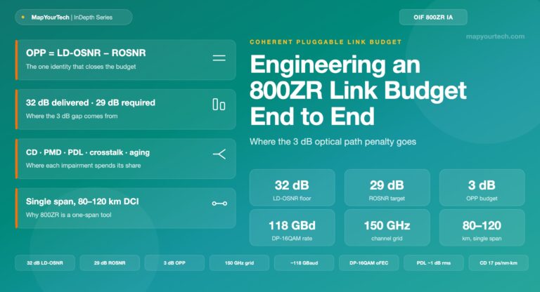
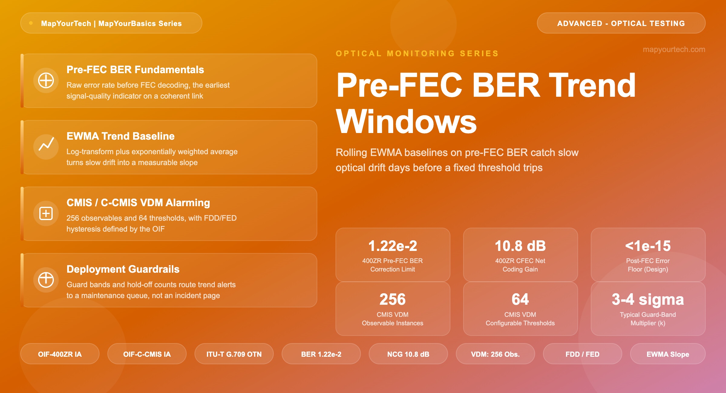
The FEC scheme in use sets the ceiling this metric is measured against. Older hard-decision codes built on ITU-T G.709 Reed-Solomon framing correct into the low 10-3 pre-FEC BER range before failing (vendor-typical figure, legacy hard-decision FEC). Modern coherent modules use stronger codes: the OIF 400ZR Implementation Agreement specifies a concatenated FEC combining a soft-decision inner Hamming code with a hard-decision outer staircase code, correcting up to a pre-FEC BER of 1.22 x 10⁻² at a net coding gain of 10.8 dB, with a design post-FEC error floor below 1.0 x 10⁻¹⁵ (standard-specified, OIF-400ZR Implementation Agreement). The two numbers are not interchangeable, and a monitoring baseline built for one FEC generation will trip at the wrong point on the other.
Common Management Interface Specification (CMIS) and its coherent extension, C-CMIS, formalize how a host reads this signal. The versatile diagnostic monitor (VDM) mechanism defined by the Optical Internetworking Forum (OIF) supports up to 256 observable instances and 64 configurable thresholds per module, with pre-FEC BER and estimated signal-to-noise ratio (eSNR) as standard observable types (standard-specified, OIF-CMIS and OIF-C-CMIS Implementation Agreements). The 400ZR IA layers two named conditions on top of the raw counter: FEC Detected Degrade (FDD) and FEC Excessive Degrade (FED), each with independent activate and clear BER thresholds so the alarm carries built-in hysteresis rather than chattering around one crossing point.
That hysteresis solves chatter, not lead time. FDD and FED both compare the current interval's average BER against a fixed number. A link that is degrading at a rate of, say, half a decade of pre-FEC BER per month will sit below both thresholds for most of that month and then cross FED with days of warning at best. The rolling-window approach in this article does not replace FDD or FED; it adds a second alarm layer that watches the trend of the same counter rather than its instantaneous value, and reports margin loss on a timescale useful for planning a maintenance window instead of a same-day dispatch.
3. Technical Details
Why the raw counter needs transforming first
Pre-FEC BER spans many orders of magnitude and its sample-to-sample noise scales with its own magnitude, so averaging the linear value produces a baseline that is dominated by whichever sample happened to be largest in the window. Taking the base-10 logarithm first converts a multiplicative process into an additive one: log10(BER) behaves, to a reasonable approximation over the timescales relevant here, like a signal with roughly constant-variance noise riding on a slowly moving mean. Every step below operates on this log-transformed series, not on the raw BER.
Where the trend engine sits in the monitoring path
x_t = log10(BER_t)                          // one sample per PM interval

EWMA_t = alpha * x_t + (1 - alpha) * EWMA_(t-1)
Var_t  = alpha * (x_t - EWMA_(t-1))^2 + (1 - alpha) * Var_(t-1)

// guard band, k typically 3-4 (standard-deviation multiplier)
Upper_t = EWMA_t + k * sqrt(Var_t)

// slope over the trailing window of N samples, least-squares fit
slope_t = d(EWMA)/dt   over trailing N samples

ALARM if x_t > Upper_t  AND  slope_t > slope_min
for M consecutive intervals // M is the hold-off countA 400ZR link on a metro DCI span holds a pre-FEC BER near 4 x 10⁻³ for its first six months in service, well inside the 1.22 x 10⁻² FEC correction limit and far from tripping FED. A connector at one end begins accumulating contamination, and the pre-FEC BER climbs to 6 x 10⁻³ over three weeks — still roughly half the FEC limit, so no fixed threshold reacts. In log space that is a shift from -2.40 to -2.22, a slope of about 0.006 decades per day. An EWMA with a 36-sample time constant and a 3.5-sigma guard band flags sustained excursion after four consecutive out-of-band intervals, giving the operator time to schedule a connector clean and re-polish during a planned maintenance window instead of after a protection switch.
| Property | Fixed FDD/FED Threshold | Rolling-Window Baseline |
|---|---|---|
| Signal compared | Instantaneous average BER per PM interval | Trend of log(BER) across N intervals |
| Detects slow drift | Only once drift nears the FEC limit | Once slope exceeds the tuned rate, independent of absolute level |
| Typical lead time | Hours before excessive correction | Days to weeks, scaled to drift rate |
| False-alarm control | Activate/clear hysteresis (FDD/FED) | Guard band (k-sigma) plus hold-off count (M) |
| Where it breaks down | Sudden step failures (fiber cut, card reset) | Sudden step failures — needs the fixed threshold as a backstop |
A rolling-window baseline does not replace FDD/FED. A fiber cut or a card reset produces a near-instant step, not a trend, and the slope test in a window-based alarm can take several samples to notice a jump that a fixed threshold catches on the next interval. Run both alarm layers in parallel: the fixed threshold as the fast backstop for step failures, the rolling baseline as the early-warning layer for drift.
4. Practical Guidelines
- Seed the baseline from real history. Run the EWMA silently for a burn-in period — commissioning data plus at least a week of live traffic — before enabling the alarm output, so the guard band reflects this link's actual noise floor rather than an assumed one.
- Set the guard band per FEC generation, not per link count. A 400ZR CFEC-based line and a legacy hard-decision FEC line have different pre-FEC BER dynamic ranges; a shared alpha and k across both will over-alarm on one and under-alarm on the other.
- Keep the hold-off count long enough to survive one bad interval. A single noisy PM sample should never page anyone; requiring M consecutive out-of-band intervals before raising the alert absorbs normal measurement jitter.
- Feed eSNR alongside pre-FEC BER where the module supports it. The OIF C-CMIS specification recommends eSNR for alarming because it is a vendor- and implementation-independent function of pre-FEC BER near the FEC threshold, which makes it a useful cross-check against a drift alarm built on BER alone (standard-specified, OIF-C-CMIS Implementation Agreement).
- Route the alarm to a maintenance queue, not an incident queue. A trend alarm is a planning signal. Pairing it with the same severity and paging policy as a hard failure defeats the purpose of the extra lead time it buys.
5. Key Takeaways
Takeaway: Pre-FEC BER is the earliest usable signal-quality indicator a coherent module exposes, but a fixed alarm threshold — even one built with FDD/FED-style hysteresis — only fires once drift is close to the FEC correction limit. An EWMA baseline on log(BER), paired with a slope test and a hold-off count, converts the same counter into a days-to-weeks early-warning signal for slow degradation while leaving the fixed threshold in place as the fast backstop for sudden step failures. Tune alpha, k, and M against each FEC generation's own dynamic range rather than reusing settings across link types.

Optical Communications & Network Automation Expert | Author of 3 Books for Optical Engineers | Founder, MapYourTech
Optical networking engineer with nearly two decades of experience across DWDM, OTN, coherent optics, submarine systems, and cloud infrastructure. Founder of MapYourTech. Read full bio →
Follow on LinkedInRelated Articles on MapYourTech


Continue Reading This Article
Sign in with a free account to unlock the full article and access the complete MapYourTech knowledge base.