
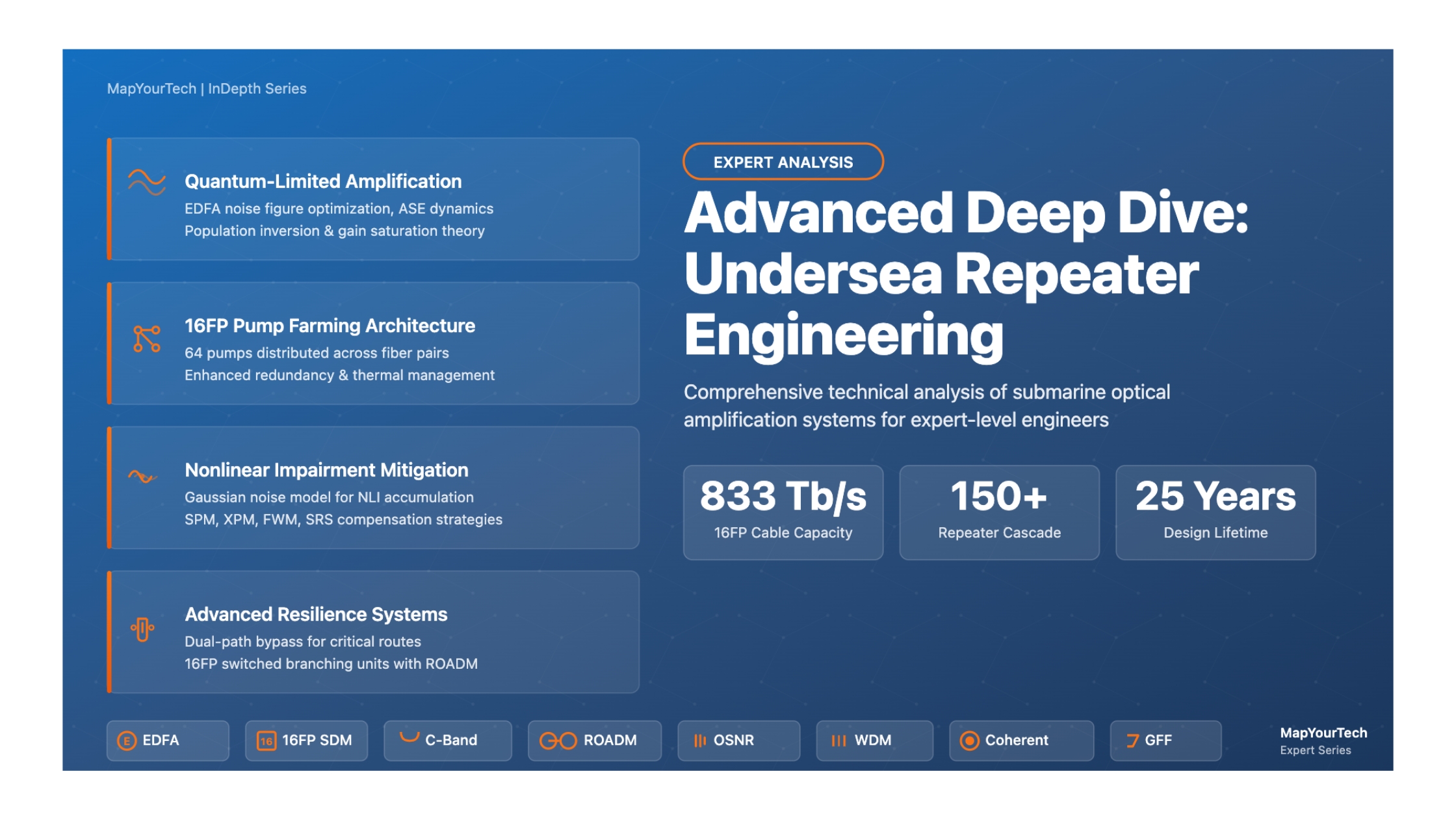

Advanced Deep Dive: Undersea Repeater Engineering
Comprehensive Technical Analysis of Submarine Optical Amplification Systems for Expert-Level Engineers
Introduction
Undersea repeaters represent one of the most critical and sophisticated elements in transoceanic fiber optic communication systems. These submerged amplification nodes must operate continuously for 25 years in harsh deep-sea environments without maintenance, making their design and engineering among the most demanding challenges in telecommunications. Modern submarine systems spanning thousands of kilometers rely on cascades of 150 or more repeaters, each compensating for optical fiber attenuation while maintaining stringent performance requirements for noise figure, gain flatness, and output power stability.
The evolution from regenerative electronic repeaters to all-optical amplification based on erbium-doped fiber amplifiers (EDFAs) revolutionized submarine communications in the 1990s, enabling wavelength division multiplexing (WDM) and capacity scalability previously impossible with regeneration. Contemporary undersea repeater design involves sophisticated optimization of pump laser architectures, gain equalization strategies, nonlinear impairment mitigation, and reliability engineering to support multi-terabit system capacities over ultra-long distances. State-of-the-art deployments now achieve 16 fiber pairs (16FP) per repeater housing with aggregate cable capacities exceeding 800 terabits per second, representing a dramatic leap from earlier 8FP architectures. This technical analysis examines the advanced theory, architectural considerations, implementation challenges, and performance optimization techniques that define modern undersea repeater engineering.
Submarine Cable System Architecture with Repeater Chain
1. Advanced Concepts & Theoretical Foundations
1.1 Quantum-Limited Amplification Theory
The fundamental performance limits of optical amplifiers are governed by quantum mechanics and the Heisenberg uncertainty principle. For any phase-insensitive linear amplifier, the minimum noise figure approaches 3 dB (factor of 2) in the high-gain limit, representing the quantum noise floor arising from spontaneous emission. The noise power spectral density added by an EDFA can be expressed rigorously as:
where nSP is the population inversion factor (spontaneous emission factor), G is the amplifier gain, h is Planck's constant, and ν is the optical frequency. The first term represents amplified spontaneous emission (ASE) noise, while the second term accounts for vacuum field fluctuations. The noise figure NF relates to the population inversion factor through:
In practical submarine EDFAs utilizing 980 nm pumping, achieving nSP values approaching 1.3-1.5 yields noise figures of 4.5-5.0 dB, which includes contributions from component insertion losses, incomplete population inversion, and backward ASE recirculation. The stringent NF requirements for transoceanic systems—often specified below 4.7 dB—drive sophisticated engineering solutions including minimized input coupling losses (below 0.1 dB for 980/1550 nm WDM couplers), optimized erbium doping profiles, and strategic isolator placement.
Advanced Insight: Double Rayleigh Backscattering Noise
Read the Full Analysis with Premium
The remaining 89% of this article — the design numbers, trade-offs and field guidance — is part of MapYourTech Premium, along with the full premium library, courses and professional tools.



Course Title
Course description and key highlights
Course Content
Course Details
Celebrating 1,000+ LinkedIn posts
3 hours of Premium Pro, free
The full Premium Pro library, unlocked with one click. The clock starts the moment you check out and runs for 3 full hours - pick a time when you can make the most of it.
- Courses
- Interview preparation content
- Career development posts
- Simulators
- Calculators
- Market research
No card, nothing to cancel. One pass per person. Sign in or create a free account at checkout.
Follow MapYourTech on LinkedIn for regular updates and future promos.
New articles, tool releases and member offers, posted as they go live.
Follow MapYourTech on LinkedIn
Enjoying MapYourTech? Follow us on LinkedIn. One click and this stops appearing.
- New technical articles and tool releases, posted as they go live
- Course launches and member offers before they reach the site
- Standards and industry updates worth an optical engineer's time
New articles, tool releases and member offers, posted as they go live.