
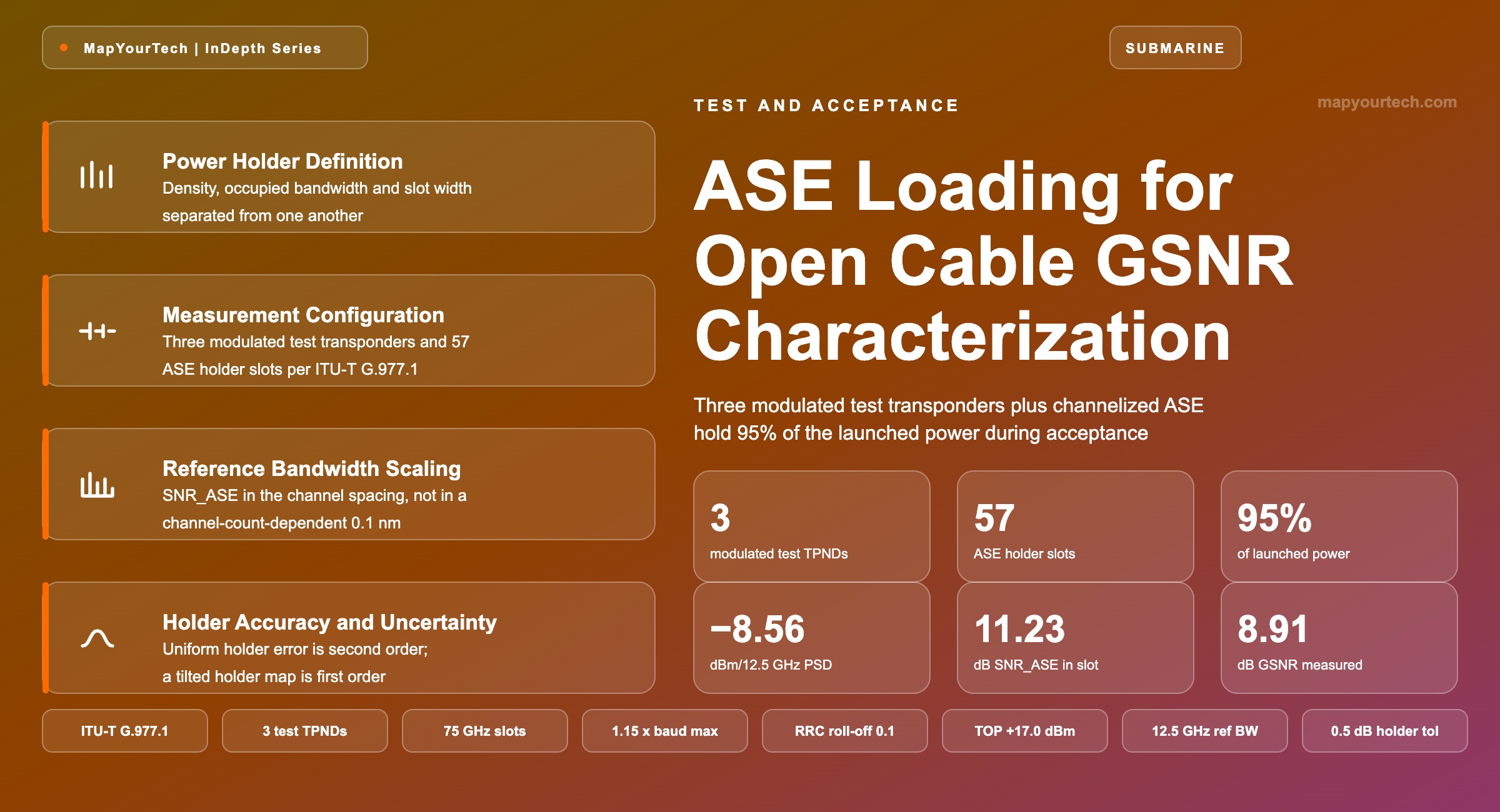
ASE Loading as Power Holder During GSNR Characterization
Filling a submarine spectrum with test transponders is impractical, so three modulated channels plus continuous or channelized amplified spontaneous emission hold the remaining launched power — and the channelized form also delivers the SNRASE measurement.
A test condition omitted is a specification withdrawn.
What You Will Learn
- Define an ASE power holder against the adjacent quantities it is confused with — per-slot power, power spectral density and occupied bandwidth (Section 2, Figure 1).
- Place three modulated test transponders and 57 holder slots so that the launched condition stays at 60 filled slots and +17.0 dBm at every sweep step (Section 3, Figure 2).
- Select between continuous and channelized ASE on the one property that separates them — access to the inter-slot noise floor at 0.1 nm resolution (Section 4, Table 2).
- Construct the reciprocal chain from Q2 to GSNR: SNRTOT 8.00 dB and SNRm 17.00 dB give SNREXT 8.58 dB, and SNRi 20.00 dB gives GSNR 8.91 dB (Section 5).
- Convert between reference bandwidths and check the two published forms against each other — 19.0 dB in 0.1 nm equals 11.23 dB in a 75 GHz slot (Section 6, Table 4).
- Quantify what a holder level error costs: ±0.5 dB uniform gives 0.06 dB of GSNR, while +2.0 dB gives 1.00 dB (Section 9, Figure 5, Table 6).
- Anchor the nonlinear equivalence of ASE and modulated channels to the fibre dispersion map, and name where the equivalence ends (Section 10).
- Diagnose loading-related anomalies from their spectral signature, from tilted holders to a saturated Q2 reading (Section 11, Table 8).
1. Introduction
An open submarine cable is bought without transponders and accepted without them. The purchaser takes delivery of a wet plant — cable, repeaters, branching units, equalizers — and buys submarine line terminal equipment (SLTE) later, from whichever supplier has the strongest modem at the time. That separation removed the metric the industry had used for thirty years. A turnkey system was accepted against a Q-factor figure measured through the supplier's own terminals; a wet plant with no terminals attached cannot produce one. The replacement pair of metrics is SNRASE, which counts the linear noise the repeater chain adds, and the generalized signal-to-noise ratio (GSNR), which counts every propagation impairment the cable delivers to a receiver. Both are properties of the cable rather than of anyone's modem, and both are specified in ITU-T G.977.1 for transversally compatible submarine systems.
Measuring GSNR requires modulated light on the fibre, and the arithmetic of doing it at scale becomes impractical. A modern C-band fibre pair carries roughly 4.5 THz of usable spectrum; at 75 GHz spacing that is 60 channels, and a transpacific cable with 16 fibre pairs would need close to a thousand test transponders to fill every slot on every pair at once. G.977.1 resolves the problem by separating the two jobs a channel does during a measurement. Only three channels need to be modulated: one under test and two adjacent, so the channel under test sees realistic neighbour interference. Every other slot exists only to carry power, and amplified spontaneous emission carries power as well as a transponder does. The Recommendation calls those slots power holders, and states that they may be continuous or channelized, with the channelized form carrying the additional property that the gaps between slots let an optical spectrum analyser reach the noise floor and measure SNRASE directly.
The reason the holders cannot simply be left out sits in the repeater. A submarine erbium-doped fibre amplifier runs in deep gain saturation at a fixed total output power, so the power the three test channels receive depends entirely on how much of the band is filled beside them. Launch three channels into a chain engineered for 60 and each one arrives roughly 13 dB above its design power, deep into the nonlinear part of its operating curve, and the GSNR that comes back describes a system nobody will ever deploy. The holders are not a convenience for the test engineer; they are the condition under which the measured number means anything at all. The same reasoning drives ASE channel loading on terrestrial line systems, where shaped noise holds the amplifier operating point steady while traffic fills in over years.
This article covers the loading side of open cable characterization: what a power holder is in physical terms, how the three-transponder configuration is built and swept, how the SNR chain converts a measured Q2 into a GSNR, which reference bandwidth each quantity belongs in, and how much error a holder set to the wrong level introduces. It uses one reference case throughout — a 130-repeater line at +17.0 dBm total output power across 4.5 THz — and every number in it is computed from stated inputs rather than measured on any deployed system. The wider architecture of open cables, spectrum sharing and space division multiplexing (SDM) is covered separately in the submarine cable stack deep dive.
2. ASE Power Holder Definition and Component Terms
An ASE power holder is a block of amplified spontaneous emission placed in a frequency slot to carry the optical power a traffic channel would carry there, at the same power spectral density and across the same occupied bandwidth, so that the amplifier chain downstream sees a fully loaded spectrum. It holds power and carries no data. Its level is specified in dBm per 12.5 GHz, and its width is specified in gigahertz.
Read the Full Analysis with Premium
The remaining 87% of this article — the design numbers, trade-offs and field guidance — is part of MapYourTech Premium, along with the full premium library, courses and professional tools.
You May Also Like

-
Premium
-
August 22, 2026

-
Premium
-
August 22, 2026
-
Premium
-
August 22, 2026