
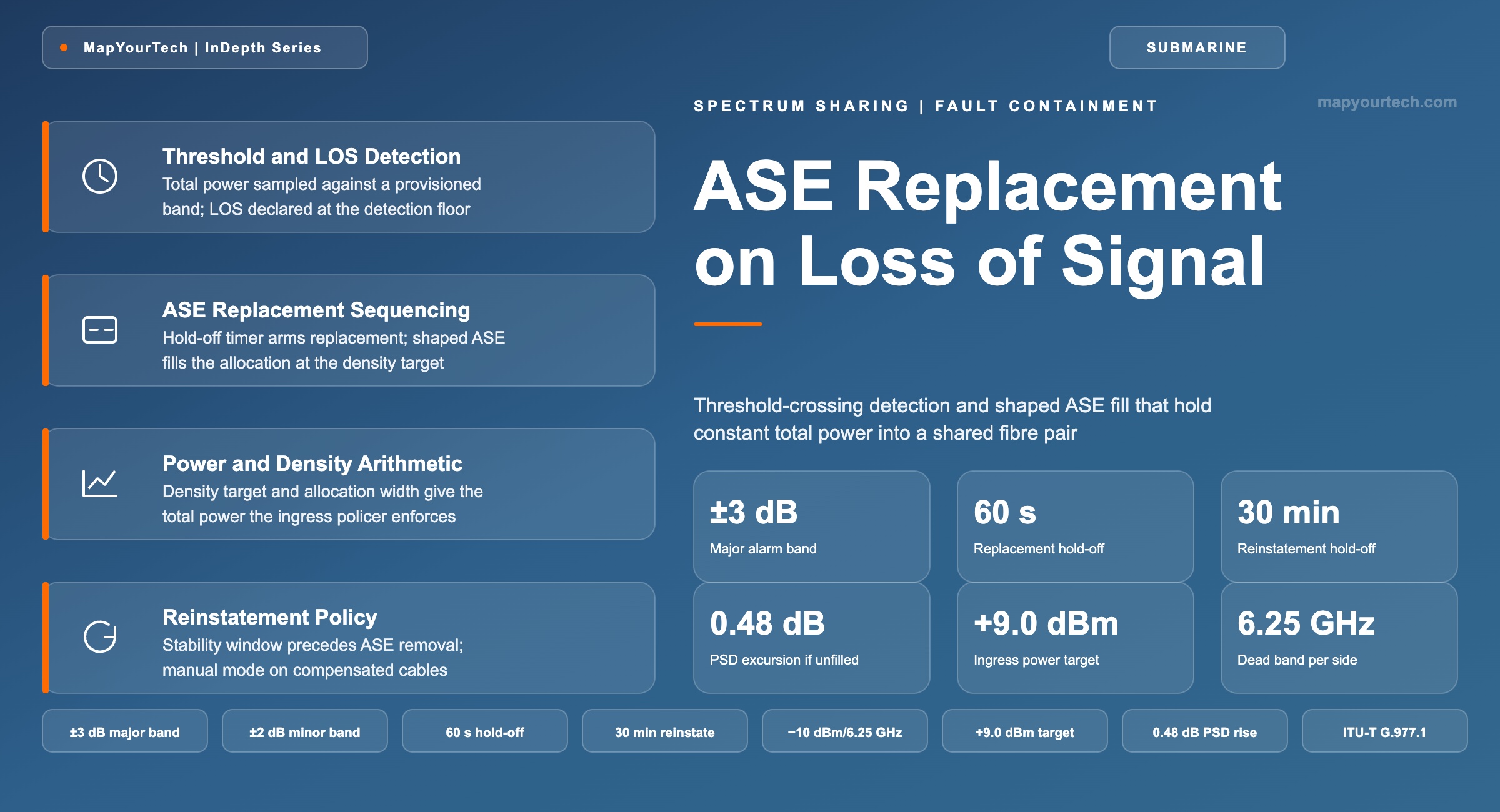
Spectrum Controller ASE Replacement on Loss of Signal
Loss-of-signal and threshold-crossing detection at a shared-spectrum interface, and the amplified spontaneous emission replacement that holds a filled spectrum and constant total power into the fibre pair.
Power concentrated into fewer channels is power spent on distortion.
What You Will Learn
- Define ASE replacement, loss of signal and threshold crossing as three separate observables, using the anatomy of Figure 1.
- Convert a power spectral density target of −10.0 dBm/6.25 GHz over a 500 GHz allocation into the +9.0 dBm total-power target the policer enforces.
- Quantify the 0.48 dB power spectral density rise that a 500 GHz gap imposes on the surviving 4.3 THz of a C-band fibre pair under total-output-power control.
- Place the monitor, policer, ASE source and combining filter of the Spectrum Management Block on the transmit chain of Figure 2.
- Select a ±3 dB major threshold, a ±2 dB minor threshold and a 60 s replacement hold-off against the exposure each setting carries.
- Build the replacement and reinstatement sequence of Figure 3, including the manual reinstatement path used on dispersion-compensated cables.
- Anchor the eleven operational parameters of Table 4 to a service contract, including the 30 minute automatic reinstatement hold-off.
- Isolate a replacement event to the user domain, the interconnect or the controller using the eight signatures of Table 7.
1. Introduction
A repeatered submarine fibre pair is engineered around one number that never changes: the total optical power its amplifier chain carries. Every repeater in the chain runs a total-output-power control loop, so the aggregate power leaving each amplifier is held constant regardless of how that power is distributed across the band. Under a single operator this is an internal design constant. Under spectrum sharing it becomes a contract term enforced at an equipment interface, because the spectrum that fills the band no longer comes from one transmitter. It arrives from two, three or four independent submarine line terminal equipment (SLTE) installations owned by parties who do not coordinate their maintenance windows and cannot see each other's channel plans.
The failure this creates has a specific shape. When one spectrum user's contribution disappears — a fibre disconnect at the interconnect, an SLTE power failure, a mis-executed channel change — the band develops a hole. The repeater chain does not know that the hole is somebody else's outage. It redistributes the constant total output power across whatever spectrum remains, raising the power spectral density of every surviving channel and moving the nonlinear operating point of users who did nothing wrong. On a wideband system the same event also changes the inter-channel stimulated Raman scattering (ISRS) tilt across the band, because the tilt scales with total launched power and with loading. The remedy is to make the hole invisible: detect the loss, wait a configured interval, and fill the allocation with shaped amplified spontaneous emission (ASE) at the same power spectral density the traffic was carrying.
The equipment that performs this is the spectrum controller, called the Spectrum Management Block (SMB) in the vendor-neutral terminology published by the SubOptic Spectrum Sharing Working Group. Its ASE replacement function is not a protection scheme for the user who failed — that user's traffic is already down, and replacement does nothing to restore it. It is a containment mechanism that protects everyone else on the fibre pair. That distinction drives every design decision in this article, from where the thresholds sit to why reinstatement is often left as a manual action.
This article covers the detection chain, the arithmetic that turns a power spectral density contract into a total-power alarm threshold, the hold-off and reinstatement sequencing, the parameters a provider and user agree before service, and the diagnostic signatures each fault class produces. It applies to uncompensated (D+) open cables carrying shared spectrum between cable landing stations or points of presence, and it flags the points where dispersion-compensated legacy cables need different settings. It does not cover the commercial structure of spectrum sales, the wet-plant design that fixes the total power in the first place, or terrestrial open line systems, where per-channel levelling and intermediate add/drop change the control philosophy entirely.
Three groups of readers get different things from the same mechanism. A user's transmission engineer needs to know which of their own behaviours will trip a threshold and how long they have to correct it. A provider's operations team needs to know what the controller will do without asking, and what it will refuse to do without a human. A network architect needs the arithmetic that connects an allocation width to a power target to an alarm band, because those three numbers are what the contract records.
2. ASE Replacement and Threshold Crossing Definitions
ASE replacement is the controlled substitution of a spectrum user's allocated frequency range with broadband amplified spontaneous emission, shaped by a filter to occupy exactly that range at the agreed power spectral density, performed by the spectrum controller when the user's input no longer meets its interface specification. The substitution is measured in dBm per reference bandwidth and holds the fibre pair's total launched power at its design value.
Read the Full Analysis with Premium
The remaining 87% of this article — the design numbers, trade-offs and field guidance — is part of MapYourTech Premium, along with the full premium library, courses and professional tools.
You May Also Like

-
Free
-
August 22, 2026

-
Premium
-
August 22, 2026

-
Premium
-
August 22, 2026