
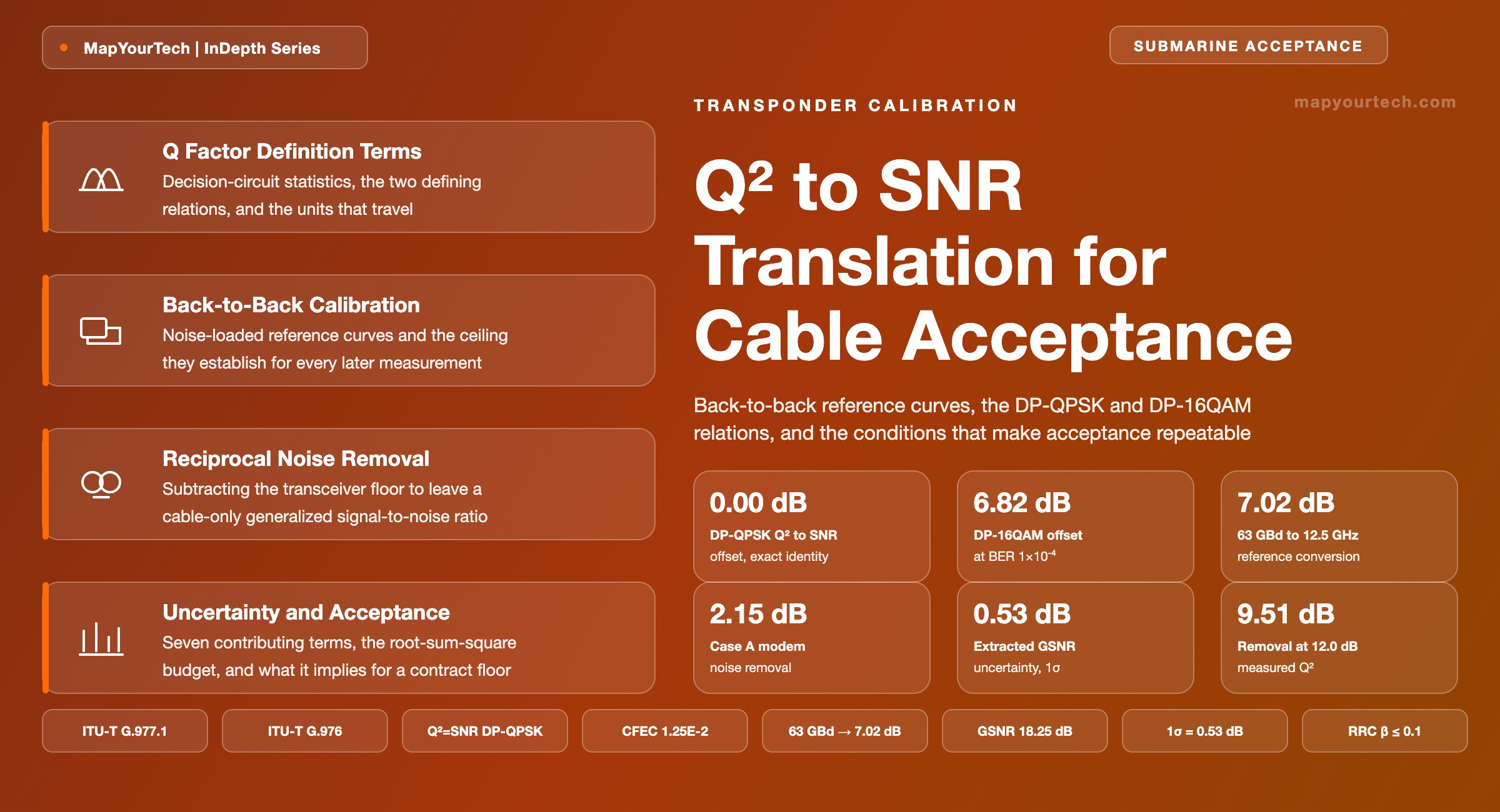
Transponder Calibration and Q-to-SNR Translation
Back-to-back reference curves, the DP-QPSK and DP-16QAM relations that convert a measured Q-squared into total SNR, and the measurement conditions that make an acceptance result repeatable across vendors.
A test condition omitted is a specification withdrawn.
What You Will Learn
- Define the Q factor as a decision-circuit ratio and convert it to pre-FEC BER with the rate-independent ladder of Table 1, where 2.0 × 10⁻² maps to 6.25 dB.
- Apply the exact DP-QPSK identity Q² = SNR and the DP-16QAM relation, whose offset runs from 6.46 to 6.82 dB across the practical BER range (Table 3).
- Read a back-to-back curve for both of its outputs: required OSNR at the code threshold and the transceiver ceiling, 19.35 dB for the worked modem (Figure 4).
- Convert between OSNR in 0.1 nm and channel SNR using the 7.02 dB factor a 63 GBd carrier carries, and the ladder of factors in Table 4.
- Strip the transceiver and interaction terms from a measured Q² of 8.60 dB down to a cable GSNR of 18.25 dB in the five steps of Figure 6.
- Quantify why the same removal costs 0.99 dB at a measured Q² of 6.0 dB and 9.51 dB at 12.0 dB on one DP-16QAM modem (Figure 8).
- Build a measurement uncertainty budget that sums to 0.53 dB at one sigma, and test a 0.65 dB acceptance margin against it (Table 6, Section 9).
- Select the metric that belongs at each stage of acceptance: OSNR, Q², SNREXT or GSNR, using the comparison of Table 8.
1. Introduction
An acceptance certificate for a submarine cable segment records one number per channel per fibre pair, and for three decades that number was a Q factor. The purchaser measured it with the supplier's own terminal equipment installed at both ends, compared it against a contracted commissioning limit, and signed. The measurement worked because the same vendor supplied the wet plant and the terminals, so the Q factor and the limit it was compared against were built from the same model and the same hardware.
Open cable procurement removed that coupling. The wet plant is delivered years before the line terminals are chosen, and the terminals may come from a supplier who had no part in the cable design. A Q factor measured with one vendor's modem and compared against a limit derived from another vendor's assumptions is not an acceptance test, because the modem's own noise sits inside the measured number and the two parties disagree on how much of it there is. ITU-T G.977.1 fixes this by specifying a cable-only quantity, the generalized signal-to-noise ratio (GSNR), and by stating the conditions under which a measured Q factor can be converted into it.
The conversion has three stages, and each one is a place where two laboratories can disagree by a decibel. A measured pre-FEC bit error ratio (BER) becomes a Q-squared value through a relation that contains no rate term and no modulation term. That Q-squared value becomes a total signal-to-noise ratio (SNR) through a relation that is specific to the modulation format, exact for dual-polarization quadrature phase shift keying (DP-QPSK) and implicit for dual-polarization 16-state quadrature amplitude modulation (DP-16QAM). The total SNR then has the transponder's own contributions removed in reciprocal form, using a transceiver noise floor obtained from a back-to-back reference curve measured on the same hardware, in the same configuration, before the cable was ever connected.
Each stage carries conditions. The BER-to-Q-squared step assumes the residual noise at the decision point is Gaussian, which holds for a dispersion-unmanaged coherent link after enough spans have decorrelated the signal phases and fails for short links and for low-dispersion fibre. The Q-squared-to-SNR step assumes a particular constellation with Gray mapping and no nonlinearity compensation, which is why open submarine cable systems restrict the test transponder to two formats rather than allowing whatever the supplier happens to ship. The removal step assumes that the transceiver noise adds as an independent Gaussian term in the same channel bandwidth, which is what makes the reciprocal subtraction legitimate.
Scope and boundary conditions: this article covers dispersion-unmanaged, single-carrier coherent transmission on repeatered submarine cable, using DP-QPSK or DP-16QAM test transponders with nonlinearity compensation disabled, and it treats acceptance of a transmission segment rather than mechanical or power-feed acceptance. Values labelled standard-specified carry their recommendation or implementation agreement. Values labelled computed are derived from the stated inputs in this article and are not measurements of any deployed system. The worked cases are constructed to expose the arithmetic and are not descriptions of a particular cable.
1.1 Transponder Contribution to the Measured Q Factor
A coherent receiver reports pre-FEC BER for a signal that has passed through its own transmitter, its own digital-to-analogue and analogue-to-digital converters, its own optical front end and its own equalizer. Every one of those stages adds noise or distortion that the receiver cannot distinguish from noise the cable added. Connect the transmitter directly to the receiver with an attenuator, add no cable at all, and the reported Q-squared is finite. That finite ceiling is the transceiver noise floor, written SNRm in the ITU-T notation, and on a submarine-class line terminal it lands in the high teens of decibels.
The size of the correction depends on where the measurement sits relative to that ceiling. For a transoceanic DP-QPSK channel operating a few decibels above the code threshold, the total SNR is far below the transceiver ceiling and removing the modem moves the answer by roughly two tenths of a decibel. For a regional DP-16QAM channel operating ten decibels higher, the same removal moves the answer by several decibels, because the measurement is close enough to the ceiling that the modem is a substantial fraction of the total noise. The correction spans 0.99 dB to 9.51 dB on one modem across that operating range (computed from the stated back-to-back ceiling, Section 8).
That spread explains why acceptance disputes concentrate on short, high-order-modulation segments rather than on long QPSK ones. On a long link the cable dominates and small disagreements about the modem shift the verdict by hundredths of a decibel. On a short link the modem and the cable are comparable, and a half-decibel disagreement about the transceiver floor propagates into a multi-decibel disagreement about the cable. The measurement conditions of Section 7 close that gap.
Takeaway: A Q factor measured through a transponder is a property of the transponder and the cable together. Acceptance needs the cable alone, and separating the two requires a back-to-back reference curve measured on the same hardware in the same configuration.
1.2 The Quantities and Their Notation
Five signal-to-noise quantities appear throughout, and conflating any two of them produces an error of several decibels. SNRTOT is what the receiver experiences, and it is the quantity the measured Q-squared converts into. SNRm is the transceiver noise floor, obtained from the ceiling of the back-to-back curve. SNRi collects the impairments that appear only in transmission and only because a transponder is present, including residual dispersion compensation error, polarization dependent loss (PDL) interaction and equalization enhanced phase noise (EEPN). SNREXT is what remains after the transceiver floor is removed, and GSNR is what remains after SNRi is removed as well. Only GSNR is a property of the cable.
All five are referred to the channel bandwidth, which for a matched root-raised-cosine receiver equals the symbol rate. OSNR, by contrast, is referred to a fixed 0.1 nm window, which at 1550 nm is 12.5 GHz. The two differ by the ratio of those bandwidths, and at 63 GBd that ratio is 7.02 dB (computed). The conversion and the ladder of factors for other symbol rates appear in Section 7; OSNR fundamentals covers the reference-bandwidth definition itself in more detail.
2. Q Factor Definition and Component Terms
The Q factor is the signal-to-noise ratio measured at the decision circuit in voltage or current units, formed as the separation between the mean levels of the two symbol states divided by the sum of their standard deviations. It is dimensionless. Expressed in decibels it is conventionally written as Q-squared, equal to twenty times the base-ten logarithm of the linear Q, so that a Q of 3.09 corresponds to a Q-squared of 9.80 dB (standard-specified, ITU-T G.976 Annex A).
Read the Full Analysis with Premium
The remaining 89% of this article — the design numbers, trade-offs and field guidance — is part of MapYourTech Premium, along with the full premium library, courses and professional tools.
You May Also Like

-
Free
-
August 22, 2026

-
Premium
-
August 22, 2026

-
Premium
-
August 22, 2026