Fibre Effective Area Selection for Transoceanic Spans
How the 80 to 153 µm² range trades nonlinear tolerance against bend loss, Raman efficiency and the number of fibre pairs a cable can carry.
Every optimum is the boundary between two different failures.
What You Will Learn
- Define effective area from the mode intensity integral of ITU-T G.650.2 and separate it from mode field diameter, core diameter and effective length.
- Compute the nonlinear coefficient from effective area and the nonlinear index, and reproduce 0.69 1/(W·km) for a 153 µm² fibre at 1550 nm.
- Convert an effective-area change into a GSNR change at the optimum launch power using the one-third rule, and check it against a published 9,000 km design set.
- Read the macrobending allowance that ITU-T G.654.D grants over G.654.B and explain what large effective area costs mechanically.
- Relate the Raman gain coefficient to effective area and decide which fibre suits an unrepeatered span.
- Select an effective area for a transoceanic SDM cable, a maximum-spectral-efficiency cable and a festoon link.
1. Introduction
A transoceanic cable carries one fibre type for twenty-five years. The repeaters can be re-pumped within their design envelope, the terminal equipment is replaced two or three times over the life of the system, and the spectrum can be re-planned, but the glass on the seabed is the one element nobody revisits. Choosing its effective area is therefore a single irreversible decision taken years before the first wavelength is turned up, and the commercial range runs from about 80 µm² to 153 µm² across the fibres offered for submarine cable.
Larger effective area spreads the guided mode over more silica, which lowers the optical intensity for a given launch power and reduces the nonlinear interference the span generates. That is the whole benefit, and it is worth roughly 1.8 dB of generalized signal-to-noise ratio between the two ends of the commercial range. Against it sit four costs: the fibre itself is more expensive, the mode is less tightly confined and so more sensitive to bending, the Raman gain coefficient falls in proportion, and the coating and cabling constraints that follow from weaker confinement limit how many fibres fit inside a repeater housing and a cable core.
That last item changed the industry's answer. When a cable carried eight fibre pairs and the design objective was capacity per fibre pair, 150 µm² was the obvious choice. When a cable carries twenty-four fibre pairs and the design objective is capacity per cable under a fixed shore power budget, an 80 µm² or 110 µm² fibre that costs proportionally less can win on total capacity even though each fibre pair carries less. This article defines effective area from first principles, derives what it does to the nonlinear coefficient and to GSNR, works the trade-offs across the commercial range, and maps each choice to a system class. It covers repeatered transoceanic systems and unrepeatered links; cable mechanical design and repeater electronics are treated only where they bound the fibre choice.
2. Effective Area Definition and Mode Field Terms
Effective area is the cross-sectional area over which the guided optical power of a single-mode fibre behaves as if it were uniformly distributed, expressed in square micrometres. It is defined from the radial near-field amplitude of the fundamental mode rather than from any geometric feature of the glass, and it fixes the optical intensity, and therefore the strength of every Kerr nonlinearity, at a given launch power.
2.1 Distinctions From the Adjacent Quantities
Effective area against mode field diameter. Mode field diameter measures how wide the mode is, and it governs splice loss between two fibres; effective area measures how the power is distributed, and it governs nonlinearity. The two are related but not interchangeable, and only one appears in each calculation.
Effective area against core diameter. Core diameter is a fabrication dimension of the glass. Effective area is a property of the propagating mode, which extends well beyond the core into the cladding, so two fibres with the same core diameter and different index profiles carry different effective areas.
Effective area against effective length. Effective length converts a span of attenuating fibre into the equivalent length of lossless fibre for nonlinear accumulation. Both quantities enter the nonlinear phase shift, effective area through the intensity and effective length through the distance over which that intensity persists, and confusing them puts a span-length dependence into a fibre parameter that has none.
Aeff = 2π [ ∫ E2(r) r dr ]2 / ∫ E4(r) r dr γ = 2π n2 / (λ · Aeff)
Where:
- Aeff — effective area in m2, quoted on datasheets in µm²; commercial submarine values 80–153 µm²
- E(r) — scalar near-field amplitude of the fundamental mode at radius r, both integrals taken from 0 to infinity
- γ — nonlinear coefficient in 1/(W·km); submarine values 0.69–1.32 1/(W·km)
- n2 — nonlinear index of silica in m2/W; reported values span roughly 2.2×10⁻²⁰ to 2.7×10⁻²⁰
- λ — wavelength in m; 1.55×10⁻⁶ at the C-band reference
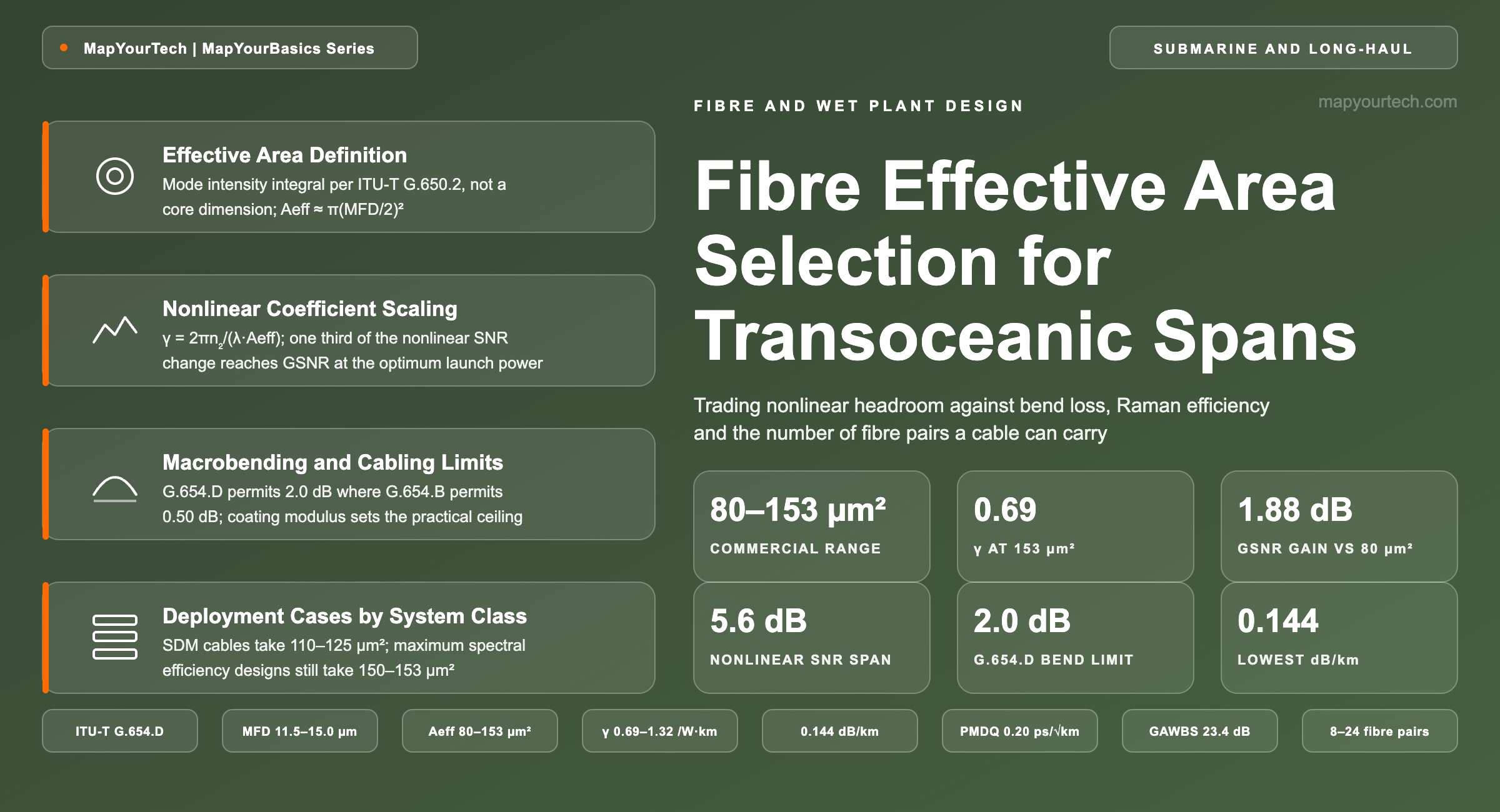
Practical Example — nonlinear coefficient of a 153 µm² fibre. A published G.654.D submarine fibre specifies a mode field diameter of 13.20–14.25 µm at 1550 nm and a typical effective area of 153 µm² (vendor claim, Corning). The Gaussian approximation Aeff ≈ π(MFD/2)2 inverts 153 µm² to a mode field diameter of 13.96 µm, which sits inside that specified window, so the approximation is sound for this profile class. Taking n2 = 2.6×10⁻²⁰ m2/W gives γ = 2π × 2.6×10−20 / (1.55×10−6 × 153×10−12) = 6.9×10⁻⁴ 1/(W·m), or 0.69 1/(W·km). The same arithmetic at 80 µm² returns 1.32 1/(W·km), a factor of 1.9.
Two checks confirm the approximation rather than assume it. A 115 µm² fibre inverts to a mode field diameter of 12.10 µm against a specified 11.9 ± 0.5 µm, and a 125 µm² fibre inverts to 12.62 µm against a specified 12.5 ± 0.5 µm (vendor claim, Corning). Both land inside the datasheet tolerance, which is why a mode field diameter quoted without an effective area still supports a first-pass nonlinear estimate. The full parameter set behind those datasheet numbers is treated in the complete single-mode fibre parameter reference.
Takeaway: Effective area is a mode property with units of area, and it enters system design through exactly one channel — the nonlinear coefficient γ = 2πn2/(λAeff). Everything the rest of this article says about capacity follows from that inverse proportionality; everything it says about cost and density follows from what the fibre had to give up to widen the mode.
3. Nonlinear Interference and the Launch Power Optimum
A repeatered submarine span accumulates two noise contributions that move in opposite directions with launch power. Amplified spontaneous emission from the erbium-doped fibre amplifiers is fixed by the amplifier gain and noise figure, so raising launch power improves the ASE-limited signal-to-noise ratio at 1 dB per dB. Nonlinear interference generated in the fibre grows as the cube of channel power, so the nonlinear signal-to-noise ratio degrades at 2 dB per dB. An optimum exists where the two slopes cross, conventionally placed at the point where nonlinear interference power reaches half the accumulated ASE power, and the launch power at that point is the nonlinear threshold.
3.1 Nonlinear Coefficient Scaling With Effective Area
Nonlinear interference power scales as the square of the nonlinear coefficient, and γ is inversely proportional to effective area, so the nonlinear signal-to-noise ratio changes by 20·log10 of the effective-area ratio. Moving from 110 µm² to 150 µm² improves it by 2.70 dB; moving from 110 µm² to 80 µm² degrades it by 2.77 dB. Those are not GSNR changes, because the system responds by re-optimizing launch power. A 1 dB improvement in the nonlinear signal-to-noise ratio raises the optimum launch power by about one third of a decibel and raises the optimum GSNR by slightly less than one third of a decibel, the shortfall arising because a third noise contribution, discussed below, is largest exactly at the nonlinear threshold.
Applying that one-third rule to the 110-to-150 µm² step gives 0.90 dB of GSNR. A published 9,000 km design set puts a 150 µm² fibre at 11.7 dB GSNR and a 110 µm² fibre at 10.8 dB, a difference of 0.9 dB (modelled, submarine system design literature) — the derived value and the published design agree to the stated precision. Across the full commercial range, 80 µm² to 153 µm² is worth 5.6 dB of nonlinear signal-to-noise ratio and about 1.8 dB of GSNR. At the same 9,000 km distance the design set reaches 23.1 Tb/s per core pair on 150 µm² fibre against 20.1 Tb/s on 110 µm², so roughly 0.9 dB of GSNR buys about 15% of fibre-pair capacity. The relationship between GSNR and achievable spectral efficiency is worked through in the article on spectral efficiency and the four levers that move it.
3.2 Guided Acoustic-Wave Brillouin Scattering Dependence
Thermally excited transverse acoustic modes scatter signal photons in the forward direction with small frequency shifts, and the scattered light mixes back into the signal as crosstalk noise. Guided acoustic-wave Brillouin scattering is not a Kerr effect, but its coefficient also scales inversely with effective area, so a large-mode fibre suppresses it for the same reason it suppresses nonlinear interference. An empirical model fitted across multiple laboratories gives the associated signal-to-noise ratio as 9.8 dB + 10·log10(Aeff in µm² / distance in Mm), agreeing with measurements to within about ±0.6 dB (measured, published GAWBS characterizations).
Over a 6,600 km transatlantic route that returns 23.4 dB for a 150 µm² fibre and 20.6 dB for an 80 µm² fibre. Because noise contributions add as parallel sums in linear units, a 20.6 dB term sitting alongside an ASE-limited term near 17 dB is not negligible: guided acoustic-wave Brillouin scattering can account for up to about 10% of the total noise a subsea line adds, and its share peaks at the nonlinear threshold (measured, transoceanic transmission experiments).
The one-third rule assumes the system is operated at its nonlinear threshold. A modern SDM cable is not. Spreading a fixed repeater pump budget across twenty-four fibre pairs typically puts each pair 1–2 dB below the nonlinear threshold, where nonlinear interference contributes only 10–18% of the total noise instead of the roughly 30% it contributes at the threshold. In that operating region the GSNR benefit of a larger effective area is smaller than 0.9 dB per step, which is the technical reason the industry stopped paying for 150 µm² glass on every route.
Takeaway: Effective area buys nonlinear headroom, and the system converts about one third of that headroom into GSNR by re-optimizing launch power. The conversion factor collapses when the cable is operated well below its nonlinear threshold, so the value of a large effective area depends on the power budget per fibre pair, not on the fibre alone.
4. Design Cases Across the 80 to 153 µm² Range
Four commercial effective-area classes cover the repeatered submarine builds now being ordered: around 80 µm², around 110–115 µm², around 125–130 µm², and 150–153 µm². Attenuation improves with effective area rather than degrading with it, because a wider mode allows less cladding dopant and therefore lower Rayleigh scattering, so the two headline optical parameters move together rather than against each other.
| Effective area (µm²) | Typical attenuation (dB/km) | ITU-T category | γ (1/(W·km)) | GSNR gain vs 80 µm² (dB) | GAWBS SNR at 6,600 km (dB) | Primary application |
|---|---|---|---|---|---|---|
| 80 | 0.156 | G.654.C | 1.32 | 0.00 | 20.6 | High-count SDM cable, cost-led builds |
| 115 | 0.149 | G.654.B, G.654.D | 0.92 | 1.05 | 22.2 | Mainstream repeatered and linear SDM |
| 125 | 0.148 | G.654.B, G.654.D, G.654.E | 0.84 | 1.29 | 22.6 | Long transoceanic, shared subsea and terrestrial |
| 153 | 0.150 | G.654.D | 0.69 | 1.88 | 23.5 | Maximum GSNR per fibre pair |
Attenuation and category are vendor-published nominals (vendor claim, Corning and Sumitomo Electric datasheets). γ is computed from γ = 2πn2/(λAeff) with n2 = 2.6×10⁻²⁰ m2/W at 1550 nm. GSNR gain applies the one-third rule at the nonlinear threshold. GAWBS values apply the empirical model of Section 3.2.
Chart 1: Nonlinear coefficient (bars, left axis) and GSNR gain relative to an 80 µm² reference at the nonlinear threshold (line, right axis) against effective area. The nonlinear coefficient falls hyperbolically while the GSNR gain rises logarithmically, which is why the last 40 µm² of effective area returns less than the first 30 µm².
| Effective area (µm²) | γ (1/(W·km)) | GSNR gain vs 80 µm² (dB) |
|---|---|---|
| 80 | 1.32 | 0.00 |
| 110 | 0.96 | 0.92 |
| 125 | 0.84 | 1.29 |
| 150 | 0.70 | 1.82 |
4.1 Macrobending and Microbending Limits
Widening the mode weakens its confinement, and the standard records the consequence directly. ITU-T G.654.B and G.654.C both cap macrobending loss at 0.50 dB for 100 turns on a 30 mm radius mandrel at 1625 nm, while G.654.D — the category written for the large mode field diameters used in high-bit-rate submarine systems — relaxes the same limit to 2.0 dB (standard-specified, ITU-T G.654). A factor of four in permitted bend loss is the mechanical price of the nonlinear headroom, granted in the specification rather than argued about in a design review.
Microbending behaves the same way and is harder to specify. Sensitivity rises steeply as the mode widens and depends on the elastic modulus of the primary coating, which is why a large effective area design is a coating decision as much as a glass decision. Single-mode fibres above about 150 µm² become impractical to cable at a 125 µm² cladding diameter for exactly this reason. Quasi single-mode designs reach far larger effective areas by tolerating higher-order modes, at the cost of a multipath interference penalty, and no such fibre has been cabled and deployed.
4.2 Raman Gain Coefficient and Unrepeatered Spans
Distributed Raman amplification transfers power from a pump wavelength to the signal through the same intensity-dependent interaction that generates nonlinear interference, so its efficiency also scales inversely with effective area. Published unrepeatered line fibre data give a Raman gain coefficient near 0.35 1/(W·km) at 80 µm², 0.25 at 110 µm² and 0.17 at 150 µm² (measured, unrepeatered fibre characterizations). A designer who selects 150 µm² for its nonlinear headroom then needs roughly twice the pump power to reach the same distributed gain as an 80 µm² fibre would deliver. On a repeatered transoceanic route that trade rarely binds, because the gain comes from discrete erbium-doped amplifiers. On an unrepeatered or festoon link, where remote Raman pumping is what extends the reach, it often decides the fibre. That system class is covered in detail in the article on festoon and unrepeatered submarine link engineering.
4.3 Cable Powering and Fibre Count Economics
Submarine repeaters are fed direct current from the two cable ends, and that supply is the binding limit on how many amplifiers a cable can operate. A published 9,000 km design comparison holds the power feed equipment at a constant 17.7 kV across three line designs and varies only the pump-sharing index and the fibre. A high-spectral-efficiency design with 150 µm² fibre, 73 km repeater spacing and 19.0 dBm repeater output supports 14 core pairs at 11.7 dB GSNR for 323 Tb/s. An SDM design with 110 µm² fibre, 80 km spacing and 18.0 dBm output halves the repeater voltage drop through a four-pumps-per-four-fibre-pairs sharing arrangement, supports 24 core pairs at 10.8 dB GSNR, and reaches 482 Tb/s (modelled, submarine system design literature). The premium fibre delivers the higher GSNR and the cheaper fibre delivers 49% more cable capacity from the same voltage.
The cost asymmetry is what makes that arithmetic work. Reducing effective area from 150 µm² to 110 µm² or 80 µm² lowers fibre-pair capacity by a bounded amount, and lowers fibre cost by proportionally more, so the saving funds additional parallel paths. The same reasoning appears in the SDM deployment roadmap and in the design of open cables with GSNR-based acceptance, where fibre-pair performance is specified as a delivered GSNR rather than as a capacity.
Takeaway: Across the commercial range, effective area buys about 1.8 dB of GSNR, costs a factor of four in permitted macrobending loss, halves the Raman gain coefficient, and raises fibre price faster than it raises fibre-pair capacity. Whether that trade closes depends on whether the cable is sold by fibre-pair capacity or by total capacity.
5. Deployment Cases by System Class
5.1 Transoceanic SDM Cables
Current transoceanic builds carry between eight and twenty-four fibre pairs, and twenty-four is the practical ceiling because every amplifier along the route draws from the same finite shore voltage and current budget (measured, industry transport network reviews). A 50,000 km five-continent system announced by a hyperscale operator uses a 24-fibre-pair design, and that count is now the reference point for new long-haul routes rather than an outlier (vendor claim, operator announcement). At twenty-four pairs each fibre operates well below its nonlinear threshold, the GSNR benefit of a large effective area is compressed, and 110–125 µm² fibre is the usual selection. Fibre cost, coating diameter and cabling density carry more weight in the decision than the nonlinear coefficient does.
5.2 Maximum Spectral Efficiency Systems
A cable built for the highest capacity per fibre pair inverts every one of those priorities. Fewer fibre pairs concentrate the available pump power, each pair runs at or near its nonlinear threshold, and the full one-third conversion of nonlinear headroom into GSNR applies. Here 150–153 µm² fibre with attenuation near 0.150 dB/km earns its price, shortening the repeater count for a given GSNR and lifting the achievable modulation order. Routes where a small number of owners each need a very high capacity per pair, and routes short enough that the GSNR target is comfortable, both fall into this class. Nonlinear compensation in the receiver adds to the same budget from the other end, and its cost is analysed in the article on nonlinearity compensation approaches.
5.3 Unrepeatered and Festoon Links
An unrepeatered span has no submerged amplifier, so its reach comes from launch power, remote optically pumped amplification and distributed Raman gain. Effective area helps on the first term and hurts on the third. Practice splits the span: a large effective area, positive dispersion fibre on the launch side where the signal power is highest and nonlinear generation dominates, and a smaller effective area fibre toward the receive end where Raman efficiency matters and the signal is already attenuated. Commercial unrepeatered portfolios are built around exactly this split, spanning 80 µm² through 150 µm² within one product family.
5.4 Regional Systems and the Terrestrial Crossover
ITU-T G.654.E was written for terrestrial deployment with a tightened mode field diameter range of 11.5–12.5 µm and a macrobending limit of 0.1 dB, matching G.652.D, so that the fibre survives duct installation and splice-tray handling (standard-specified, ITU-T G.654). A 125 µm² fibre qualified to G.654.B, G.654.D and G.654.E lets an operator specify one fibre for a subsea route and its terrestrial backhaul, which removes a mode field diameter discontinuity at the beach manhole. Where C+L operation is planned on a regional route, the lower attenuation and reduced stimulated Raman scattering tilt of a large-mode fibre also help; the band-level consequences are set out in the treatment of C+L band DWDM systems.
Takeaway: The system class selects the fibre, not the other way round. Capacity-per-cable designs take 110–125 µm², capacity-per-fibre-pair designs take 150 µm², unrepeatered spans mix two effective areas along one span, and regional routes that continue on land take the category that also satisfies the terrestrial bend specification.
6. Standards and Supplier Support
ITU-T G.654 defines cut-off shifted single-mode fibre in five categories distinguished mainly by mode field diameter, chromatic dispersion and polarization mode dispersion. Effective area itself is not a recommended value in any of them; the standard bounds mode field diameter and lets the manufacturer state the effective area that follows from the profile. The submarine system recommendations close that gap by requiring the supplier to declare it: ITU-T G.977.1 asks for the effective area of each fibre type in the cable together with the nonlinear coefficient computed as n2/Aeff, and ITU-T G.973.1 states that where large effective area fibre is adopted, the minimum effective area is to be specified (standard-specified, ITU-T G.977.1 and G.973.1). The measurement method is defined in ITU-T G.650.2.
| Category | Nominal MFD range at 1550 nm (µm) | Max attenuation at 1550 nm (dB/km) | Max PMDQ (ps/√km) | Max macrobend, 30 mm radius, 100 turns, 1625 nm (dB) | Intended application |
|---|---|---|---|---|---|
| G.654.A | 9.5–10.5 | 0.22 | 0.50 | 0.50 | Base category, 1550 nm systems |
| G.654.B | 9.5–13.0 | 0.22 | 0.20 | 0.50 | Long-haul and repeaterless submarine |
| G.654.C | 9.5–10.5 | 0.22 | 0.20 | 0.50 | Higher bit rate at base MFD |
| G.654.D | 11.5–15.0 | 0.20 | 0.20 | 2.00 | Higher bit rate repeatered submarine |
| G.654.E | 11.5–12.5 | 0.23 | 0.20 | 0.10 | Terrestrial coherent long-haul |
All values standard-specified, ITU-T G.654. Mode field diameter tolerance is ±0.7 µm in every category. G.654.E also bounds chromatic dispersion between 17 and 23 ps/(nm·km) at 1550 nm and caps attenuation at 0.25 dB/km across 1530–1612 nm.
6.1 Splice Loss and Mode Field Diameter Matching
Joining two fibres with different mode field diameters costs loss at every splice, and the mismatch term is 20·log10[(w12+w22)/(2w1w2)] dB, where w is the mode field radius. Splicing a 153 µm² fibre to a 125 µm² fibre costs 0.04 dB from mismatch alone; splicing the same fibre to an 80 µm² fibre costs 0.45 dB. On a cable with thousands of factory-length joints and every branching unit and repair splice, that difference is a line item in the attenuation budget rather than a rounding error, which is why a route is specified with one effective area class end to end wherever the design allows.
6.2 Supplier Portfolios
Three suppliers cover the submarine fibre market. Corning offers a G.654.D fibre at 153 µm² typical effective area and 0.150 dB/km typical attenuation, a fibre at 125 µm² and 0.148 dB/km nominal qualified to G.654.B, D and E, and a fibre at 115 µm² and 0.149 dB/km nominal qualified to G.654.B and D (vendor claim, Corning product information). Sumitomo Electric publishes a pure-silica-core family running from 85 µm² at 0.156 dB/km through 112 µm², 130 µm² and 150 µm², the last at 0.144 dB/km in its ultra-low-loss variant (vendor claim, Sumitomo Electric). OFS supplies a comparable ocean fibre range. Two of the three portfolios now also offer a 200 µm coating diameter option in place of the standard 250 µm, sold explicitly to raise fibre count within an unchanged cable core.
Takeaway: The recommendations specify mode field diameter and leave effective area to the supplier, so a procurement specification has to name the effective area and its minimum explicitly. G.654.D is the category that makes a 150 µm² fibre legal to cable, and it does so by relaxing the bend limit rather than by adding an effective-area requirement.
7. Directions in Fibre and Cable Density
Reduced coating diameter is the change closest to deployment, and it is one of three now reaching submarine cable. A 200 µm coating in place of 250 µm raises the fibre count that fits an unchanged pressure-vessel tube, and it is already a catalogue option on mainstream 115 µm² and 125 µm² submarine fibres. Because coating stiffness and thickness set microbending sensitivity, thinning the coating tightens the effective-area ceiling, so the two levers compete for the same margin.
Weakly coupled multicore fibre moves the same constraint further. Four cores fit inside a standard 125 µm cladding with negligible crosstalk, and a mass-produced two-core submarine fibre at 112 µm² per core and 0.158 dB/km attenuation now exists in the standard cladding diameter (vendor claim, Sumitomo Electric). A two-core fibre operated in opposite directions delivers the equivalent of 48 core pairs in a cable that would otherwise carry 24, which moves the density constraint from the cable core to the repeater power budget. Repeater packaging and the powering limit are treated in the article on deep-sea optical repeater design.
Hollow-core fibre remains the least settled of the three. Guiding in air removes the silica nonlinearity that effective area exists to manage, and it lowers latency by about 30% for the same route length, but cabling, splicing and the twenty-five-year reliability case remain unproven for submarine service. Its splice behaviour differs from solid glass in ways that a solid-fibre mode field calculation does not predict, which is the subject of the hollow-core splice loss simulator. For a cable ordered today, the effective-area decision remains a choice within the 80–153 µm² silica range, and it remains bounded by shore powering rather than by glass. A first-pass system view of that budget can be built with the submarine link simulator, and the wider architecture context sits in open submarine cable systems.
Takeaway: Density work and effective area pull against each other. Thinner coatings and multicore designs both raise fibre count, and both do so by tightening the mechanical margin that a large effective area consumes.
8. Conclusion
Effective area enters submarine system design through one equation and leaves through two. It sets the nonlinear coefficient as γ = 2πn2/(λAeff), which fixes how much launch power a span tolerates and therefore, after re-optimization, about one third of that headroom as GSNR. It also sets how tightly the mode is confined, which fixes bend sensitivity, coating requirements, cabling density and price. The first path argues for 150 µm² and the second argues for 80 µm², and the cable's commercial objective decides between them.
For a capacity-per-cable design under a hard shore power limit, 110–125 µm² is the current answer: it gives up under 1 dB of GSNR against the premium fibre, keeps attenuation at or below 0.150 dB/km, satisfies G.654.D and often G.654.E as well, and is available in a 200 µm coating for density. For a capacity-per-fibre-pair design running at the nonlinear threshold, 150–153 µm² still earns its price. For unrepeatered spans, the Raman gain coefficient inverts the ranking and a split-span design with two effective areas outperforms either fibre alone. Whichever class applies, the procurement specification should state the effective area, its minimum, the nonlinear coefficient and the Raman gain coefficient, because ITU-T G.654 bounds none of them.
9. References
- ITU-T G.654 — Characteristics of a cut-off shifted single-mode optical fibre and cable, ITU-T Study Group 15.
- ITU-T G.977.1 — Transverse compatible dense wavelength division multiplexing applications for repeatered optical fibre submarine cable systems, ITU-T Study Group 15.
- ITU-T G.973.1 — Longitudinally compatible DWDM applications for repeaterless optical fibre submarine cable systems, ITU-T Study Group 15.
- ITU-T G.650.2 — Definitions and test methods for statistical and non-linear related attributes of single-mode fibre and cable, ITU-T Study Group 15.
- Corning Incorporated, Vascade EX3000, EX2500 and EX2000 Optical Fiber Product Information, Corning Optical Communications.
- Sumitomo Electric Industries, Z Fiber Series Submarine Optical Fibers, Sumitomo Electric.
- M. Bolshtyansky, Impact of Spontaneous Guided Acoustic-Wave Brillouin Scattering on Long-Haul Transmission, Optical Fiber Communication Conference.
Related Articles on MapYourTech