
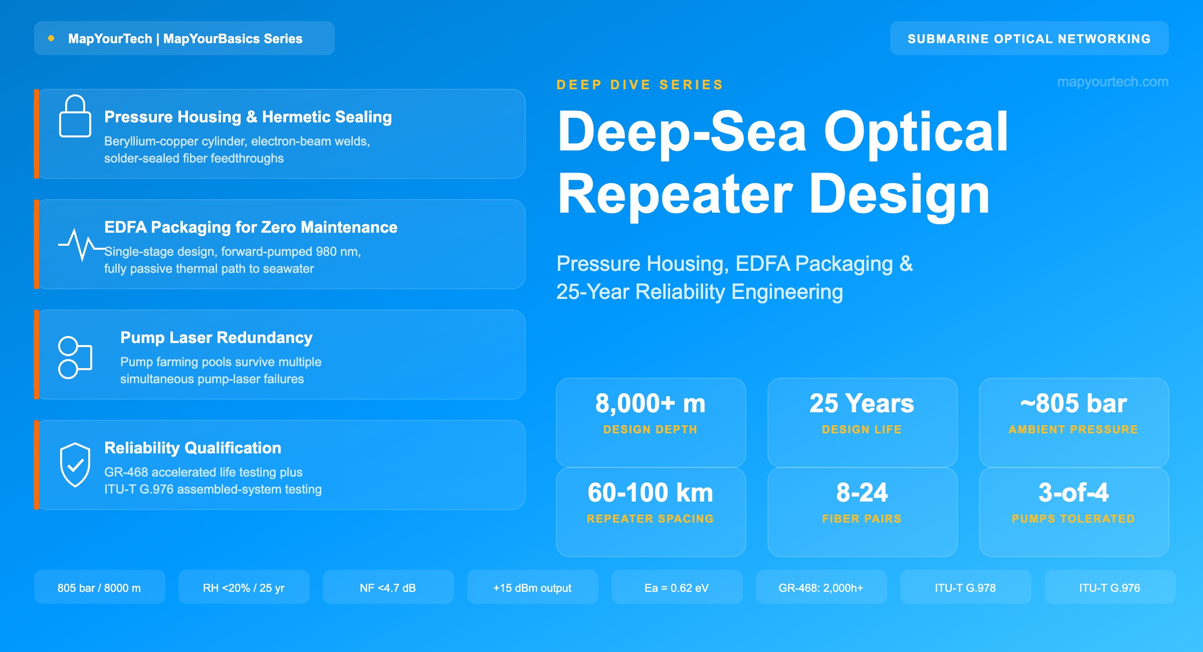
Deep-Sea Optical Repeater Design: Pressure Housing, EDFA Packaging, and 25-Year Reliability
Inside the sealed cylinder that amplifies light 8,000 meters underwater for twenty-five years without a single service visit — the materials, the packaging, the redundancy math, and the tests that prove it will survive.
1. Introduction
A submarine optical repeater is built once, tested once, lowered onto the seabed once, and then left alone for a quarter century. There is no service technician, no spare-parts shelf, and no scheduled maintenance window. If a repeater 4,000 km from either shore station degrades, the only remedy is a cable ship, a grapple, and a repair that costs millions of dollars and takes weeks — assuming the fault can even be localized precisely enough to cut the right stretch of cable. This operating model, unique among powered electronic systems, is why submarine repeater engineering treats the pressure housing, the erbium-doped fiber amplifier (EDFA) inside it, and the qualification testing behind both as a single connected design problem rather than three separate ones.
This article works through that problem at the component and mechanism level. It covers the materials and sealing techniques that keep seawater and hydrogen out of the housing for 25 years, the packaging choices that let an EDFA run at full output with no active cooling, the pump-laser redundancy architectures that trade coupler complexity for survivability, and the accelerated-life testing regimes — component-level and system-level — that stand in for the field failure data no operator wants to generate. Recommendation ITU-T G.978 (the current characteristics specification for optical fibre submarine cables) and the related G.97x family set the framework; Telcordia's GR-468-CORE sets the component-level bar for the optoelectronics inside. Between them, they explain why a device this remote can be trusted with global internet traffic for a quarter century. Readers new to the broader repeater picture — how signals actually survive 20,000 km of undersea travel — may want that companion overview alongside this deeper mechanical and reliability treatment.
2. The Deep-Ocean Operating Environment
Every design decision in a submarine repeater traces back to four environmental facts: crushing hydrostatic pressure, a constant near-freezing heat sink with no active cooling, a corrosive and hydrogen-generating chemical environment, and mechanical shock during laying and recovery. None of these is exotic in isolation — pressure vessels, cold-climate electronics, and corrosion-resistant alloys are mature engineering fields — but the combination, held for 25 years with zero physical access, is what makes this one of the more demanding sealed-electronics design problems in telecommunications.
Hydrostatic Pressure
Pressure increases linearly with depth in seawater because the weight of the water column above any point acts directly on that point. The relationship is simple, but the consequence at ocean-trench depths is not.
Practical Example — Pressure at 8,000 m
At h = 8,000 m: ρgh = 1,025 × 9.807 × 8,000 ≈ 80,414,000 Pa ≈ 804.1 bar. Adding atmospheric pressure gives a total of approximately 805 bar — roughly 805 times the pressure at sea level, and well over 11,000 psi on every square inch of the housing wall. This is a calculated value from standard seawater density and gravitational constants, not a measured field figure; local pressure varies slightly with salinity and temperature, which is why housing qualification tests use a margin above the nominal design depth rather than the bare calculated value.
Figure 1: Hydrostatic pressure versus ocean depth, calculated from seawater density and standard gravity. The relationship is linear — every additional 1,000 m adds approximately 100.5 bar.
Thermal Environment
Deep-ocean water sits at a nearly constant 1–4°C regardless of surface season, which sounds like a favorable heat sink until the transfer path is considered. The repeater housing is metal in direct contact with seawater, so heat generated by pump lasers and drive electronics conducts outward through the housing wall with no fan, no forced convection, and no thermoelectric cooler doing the heavy lifting — active cooling draws electrical power that the shore-fed cable simply does not have a surplus of once hundreds of kilometers of conductor resistance are accounted for. The design response is passive: mount high-dissipation parts directly against the metal housing wall to minimize thermal contact resistance, and size the housing's exposed surface area so conduction to the surrounding water keeps junction temperatures low without any moving parts. Section 4 covers how this constrains EDFA and pump-laser packaging directly.
Chemical Environment and Design-Life Framework
Recommendation ITU-T G.978 (the current edition covers optical fibre submarine cable characteristics) frames the cable and its attached hardware around four threats that must be held off for the full design life: water pressure penetration, longitudinal water propagation along the cable core, chemical aggression from seawater, and hydrogen contamination — hydrogen generated by galvanic corrosion of metal parts can diffuse into the fiber core and increase attenuation over time if not controlled. The related family of recommendations — G.972 for terminology, G.973 and G.974 for repeaterless and regenerative system characteristics, and G.977 specifically for optically amplified (EDFA-based) submarine systems — together define what "designed for the system design life" means in practice: no measurable transmission-characteristic degradation from laying, burial, recovery, or long-term chemical exposure.
Takeaway: Every subsystem inside a submarine repeater is designed against the same four constraints — a calculated ~805 bar at 8,000 m, a passive-only thermal path to near-freezing water, a 25-year chemical and hydrogen-exposure budget defined by ITU-T G.978, and zero tolerance for mechanical failure during laying and recovery. These constraints do not stack independently; they compound, which is why the housing material, the sealing method, and the EDFA's internal thermal design are engineered together rather than specified in isolation.
3. Pressure Housing and Hermetic Sealing
The pressure housing is the first line of defense, and its job is deceptively narrow: keep water and gas out at the calculated depth pressure, conduct heat from the internal unit to the sea, and survive the mechanical abuse of being spooled onto a cable ship, paid out over a stern sheave, and — decades later — possibly grappled back up for a repair. Submarine repeater engineering documentation from NEC's submarine network division describes a housing built from three main parts: a cylindrical body, two cover assemblies (end caps), and two joint rings that connect the cylinder to the armored cable on each side.
Material Selection
The documented main material for this housing is a beryllium-copper alloy, chosen for a combination of high tensile strength and strong corrosion resistance in a chloride-rich, oxygenated seawater environment — properties that matter more here than low weight, since the housing sits on the seabed rather than being carried. Table 1 lays out how beryllium-copper compares with two other pressure-vessel materials used elsewhere in subsea engineering, to make the trade-offs concrete rather than abstract.
| Material | Typical Tensile Strength | Seawater Corrosion Resistance | Thermal Conductivity | Relative Density |
|---|---|---|---|---|
| Beryllium-copper alloy (documented submarine repeater housing material) | ~1,300–1,450 MPa (hardened temper) | Excellent — long-standing choice for coaxial and optical submarine repeater housings | High (~105–130 W/m·K) | ~8.3 g/cm³ |
| Titanium alloy (Ti-6Al-4V) — used in other subsea pressure-vessel applications | ~900–1,050 MPa | Outstanding — highly resistant to chloride pitting | Low (~6.7 W/m·K) | ~4.43 g/cm³ |
| High-strength steel (e.g., maraging or coated stainless) — used in general subsea pressure vessels | ~1,700+ MPa (maraging grades) | Requires coating or cathodic protection | Moderate (~15–25 W/m·K) | ~7.8–8.0 g/cm³ |
The thermal-conductivity column matters as much as strength here. A housing wall has to move heat from the internal electronics to the sea just as much as it has to hold back water pressure, and beryllium-copper's conductivity is roughly 15–20 times that of titanium — a material that wins on corrosion resistance and weight but would complicate the passive thermal path described in Section 2. This is a clear case of a material choice driven by a secondary function (heat conduction) as much as the primary one (pressure containment).
Sealing: Welding, Solder Feedthroughs, and Leak Testing
Strength alone does not keep water out; the joints do. Submarine repeater housing documentation describes two sealing technologies applied at the points where the housing is most vulnerable — the seam between the cylinder and its end caps, and the point where optical fibers must physically cross the housing wall:
- Cylinder-to-cover sealing uses electron beam welding, which produces a full-penetration, void-free metallurgical joint rather than a mechanical gasket seal that could degrade over decades under sustained pressure cycling.
- Fiber feedthrough sealing — the point where individual optical fibers must pass from the outside cable into the internal unit without breaking the pressure boundary — uses a solder seal around each fiber. This solder is reported to remain stable long enough to keep the internal relative humidity below 20% for 25 years, which matters because moisture ingress is one of the primary long-term failure mechanisms for the optoelectronics inside.
Every completed housing is then leak-tested using helium gas pressurized to the pressure equivalent of the system's maximum operating depth. Helium's small atomic radius makes it far more sensitive at finding sub-microscopic leak paths than a water or air test would be, and testing at the full depth-equivalent pressure — rather than a reduced proxy pressure — verifies the seal under the actual mechanical load it will carry in service, not just its nominal leak tightness at atmospheric conditions.
Figure 2: Simplified cross-section of a submarine repeater pressure housing, based on submarine repeater engineering documentation describing the cylinder, joint rings, welded seams, solder-sealed fiber feedthroughs, and spring-mounted internal unit.
Mechanical Isolation of the Internal Unit
Inside the housing, the internal unit — the chassis holding the EDFA and pump laser modules — is not bolted rigidly to the housing wall. It is mounted using rubber cushions and metal springs, a combination that serves two purposes at once: absorbing shock and vibration during cable-ship handling and seabed placement, and maintaining a controlled, repeatable thermal contact path between the heat-generating components and the housing wall. High-power parts such as the pump laser diodes are mounted directly against the metallic case of the sub-unit specifically to minimize thermal contact resistance, since — as established in Section 2 — conduction through the housing to the sea is the only cooling path available.
Takeaway: The pressure housing is a system, not a single part. Beryllium-copper provides both the strength to hold back ~805 bar and the thermal conductivity to carry heat outward; electron-beam-welded seams and solder-sealed feedthroughs hold humidity below 20% for the full design life; and spring-and-cushion mounting absorbs handling shock while preserving a low-resistance thermal path to the housing wall. Removing any one element for cost or simplicity reasons would break at least one of the other two.
4. EDFA Packaging for Unmaintained Operation
The amplifier inside a submarine repeater performs the same physical function as its terrestrial counterpart — stimulated emission in erbium-doped fiber pumped by a semiconductor laser — but the packaging decisions around it are shaped almost entirely by the constraints in Section 2 rather than by amplification physics alone.
Single-Stage Design as a Reliability Choice
Terrestrial long-haul EDFAs frequently use two-stage designs with a mid-stage access point for dispersion compensation modules or Raman pump insertion. Submarine repeaters typically use a single-stage design instead: one section of erbium-doped fiber, one pump-coupling stage, and isolators on each side. This is a deliberate trade against theoretical performance headroom — fewer components in the optical path directly reduces the number of independent failure points over 25 years, and since a submarine repeater cannot be swapped or repaired, minimizing part count is treated as a reliability lever, not just a cost lever.
Forward Pumping and Gain Flattening
Submarine repeater engineering documentation from NEC describes optical amplifiers implemented with a forward-pumping scheme using high-power 980 nm pump laser diodes, achieving output power above +15 dBm with a noise figure below 4.7 dB. The transmission bandwidth in that design reaches up to 40 nm, achieved through optimization of the erbium-doped fiber length combined with an individual gain flattening filter (GFF) per repeater — necessary because, as covered in that companion piece, the erbium gain spectrum is inherently non-uniform across the C-band, and that non-uniformity compounds across dozens or hundreds of cascaded repeaters if left uncorrected. These are documented design figures from submarine repeater engineering literature rather than a claim about any single vendor's current product line; modern C+L-band systems extend usable bandwidth further, at the noise-figure cost discussed in Section 6.
Pump wavelength choice follows the same logic used in terrestrial systems: 980 nm pumping offers a better noise figure and higher wall-plug efficiency than 1480 nm, which is why in-line submarine EDFAs use 980 nm almost universally, reserving 1480 nm pumping mainly for remote optically pumped amplifier (ROPA) configurations in unrepeatered systems.
Thermal Packaging Without Active Cooling
An EDFA's pump laser diode is the single largest heat source in the module. In a terrestrial line card, a thermoelectric cooler (TEC) stabilizes the laser's temperature — but TECs typically run at only 10–15% efficiency and consume meaningful electrical power, which is a luxury a shore-fed submarine repeater's power budget usually cannot absorb across dozens of repeaters in series. The packaging response, consistent with the housing-level thermal design in Section 3, is to mount the pump laser package directly against the metallic housing wall and let conduction to the surrounding seawater do the thermal work that a TEC would otherwise perform. This works because the ambient seawater temperature is stable and cold — the housing wall itself functions as a very large, constant-temperature heat sink, which is a genuine advantage of the deep-ocean environment even though it does nothing to help with the pressure and sealing challenges covered in Section 3.
Figure 3: Simplified bidirectional repeater signal path showing the amplification chain for both transmission directions, a shared pump laser pool feeding both, and the wavelength-selective-reflector supervisory loop-back used for remote health monitoring.
Takeaway: Submarine EDFA packaging trades theoretical amplification flexibility for reliability and thermal simplicity: a single-stage optical path to minimize component count, forward-pumped 980 nm diodes for efficiency, an individual gain flattening filter per repeater to hold bandwidth flat, and direct metal-to-metal thermal mounting because there is no power budget for active cooling. Every one of these choices reads as a compromise only until it is weighed against the alternative — a component that cannot be repaired for 25 years.
5. Pump Laser Redundancy and Power-Sharing
A pump laser diode is, mechanically and electrically, the most stressed active component in the repeater — it runs continuously at high drive current for 25 years with no possibility of replacement. Redundancy at the pump level is therefore not an optional reliability enhancement; it is close to mandatory, and the architecture used to provide it has evolved from simple duplication toward pooled sharing across multiple amplifier stages.
Baseline: 1+1 Pump Redundancy
The documented baseline architecture pairs two pump laser diodes per EDFA direction, multiplexing their outputs through an optical coupler so that either pump alone can sustain amplifier operation if the other fails. Each pump is controlled to hold constant output, and the system is designed so that transmission-path characteristics are maintained even with only one of the two pumps active — meaning the failure of a single pump laser produces no visible service impact, only a loss of margin.
Pump Farming: Pooled Redundancy Across Multiple Amplifiers
Modern high-fiber-count cables extend this idea into what the submarine engineering community calls pump farming: instead of dedicating a pump pair to each individual amplifier direction, a pool of pump lasers is cross-connected to a pool of EDFA gain stages through a two-stage optical coupler network. A commonly cited configuration shares four pump lasers across two EDFAs (covering both directions of one fiber pair) rather than the simpler two-pumps-per-EDFA scheme. The reliability gain is combinatorial rather than incremental: where a simple 1+1 scheme tolerates exactly one pump failure before the amplifier pair is at risk, a four-pump shared pool serving two EDFAs can tolerate up to three individual pump-laser failures — out of four — before either amplifier direction loses service, because the surviving pump or pumps can be redirected through the coupler matrix to whichever EDFA needs power.
Practical Example — Reliability of Pooled Versus Paired Redundancy
Component reliability over a mission time t follows R(t) = e−λt, where λ is the failure rate. Assume, for illustration only, a single pump laser has a 25-year survival probability of R = 0.995 (a simplified round number chosen for clarity, not a vendor-published figure). A simple 1+1 pair fails only if both pumps fail, so the pair's survival probability is 1 − (1 − R)² = 1 − (0.005)² = 0.999975. A four-pump pool serving two EDFAs, tolerant of up to three individual failures, fails only in the combinatorially rare case that all four pumps fail simultaneously: 1 − (1 − R)⁴ = 1 − (0.005)⁴ ≈ 0.9999999994. The absolute numbers here are illustrative rather than measured, but the shape of the result is the real point: each additional layer of pooled sharing pushes the failure probability down by roughly another factor of 200 for this example ratio, which is why pump farming has become the preferred architecture on high-value, high-fiber-count systems despite the added coupler-network complexity.
Figure 4: Pump farming architecture — four pump lasers pooled and cross-connected to two EDFA gain stages through an optical coupler matrix, rather than each amplifier owning a fixed, dedicated pump pair.
The Power-Feed Trade-off
Pump farming is not free. Every repeater draws its operating current from a single series DC circuit fed from the cable landing stations at each end — power feed equipment at the terminal stations pushes this current through the metallic conductor running the length of the cable, and every repeater in the chain drops some voltage across itself. A pump pool with more active or standby pump lasers, plus the additional coupler insertion loss the pooling matrix introduces, means a higher voltage drop per repeater — which, multiplied across a chain that can run to well over a hundred repeaters on a long transoceanic route, directly limits how many repeaters (and therefore how much distance and how many fiber pairs) a given power feed voltage can support. This is precisely why fiber-pair count on a submarine cable is not a free scaling knob: as covered in Section 6, industry reporting on 2026 system deployments puts practical fiber-pair counts at roughly 8 to 24 pairs per cable specifically because of this shore-fed power constraint, not because of any fundamental limit on how many fibers a cable could physically carry.
Takeaway: Pump redundancy moved from simple 1+1 pairing to pooled pump farming because the combinatorial reliability gain is large relative to the added complexity — but that complexity has a real cost in coupler insertion loss and per-repeater voltage drop, which is drawn directly from the same finite shore-fed power budget that limits fiber-pair count. Redundancy architecture and power-feed engineering cannot be optimized separately.
6. Materials, Thermal, and Fiber-Count Trade-offs
Zooming out from a single repeater to a full transoceanic system reveals a second layer of trade-offs, all of which trace back to the same finite resource: electrical power delivered from shore through a single metallic conductor.
Fiber-Pair Count Versus Power Feed
Because submarine optical amplifiers are powered exclusively from the two shore ends, repeater design and the cable's power conductor sizing are tightly coupled to the maximum number of fiber pairs a system can support. Industry analysis of 2026 submarine cable deployments notes that systems are practically limited to roughly 8 to 24 fiber pairs for exactly this reason — the amplifier chains along the route must all draw from the same finite voltage and current budget. Academic techno-economic analysis of space-division multiplexing (SDM) scaling has modeled far more extreme cases: evolving from a state-of-the-art 8-fiber-pair submarine system to a 50-fiber-pair system was estimated to yield roughly 44% in cost-per-bit savings, but only by diluting the available optical power across far more parallel spatial paths — pushing the system out of the fiber-nonlinearity-limited regime and into a purely linear one where large-effective-area fiber and digital nonlinearity compensation become unnecessary. That result is a theoretical, techno-economic model rather than a deployed-system measurement, and it illustrates why fiber-pair count, repeater pump budget, and cable conductor material are one integrated design problem, not three independent ones.
Cable conductor material is part of the same trade-off. Copper has traditionally been used for its excellent electrical and mechanical properties, but aluminum conductors — engineered to match the average cable conductivity to the system's actual power requirement — offer meaningful cost savings and are increasingly used where the added resistance can be tolerated within the power budget.
C-Band Versus C+L Band Repeaters
Extending usable bandwidth by adding the L-band alongside the C-band is another lever for capacity, but it is not free either. Published performance modeling comparing C+L-band EDFA designs against C+C (dual C-band) designs shows a noise figure penalty of roughly 0.2 dB in the C-band and the L-band each for the combined design, driven by the higher intrinsic noise figure of L-band amplification and the insertion loss of the C/L splitting components — a small but real cost that a system designer weighs against the additional spectrum gained. The MAREA cable, connecting Virginia Beach to Bilbao across eight fiber pairs with an initial design capacity of 160 Tb/s, is a documented example of a large-capacity system built with C-band EDFA technology rather than C+L, illustrating that the bandwidth-extension trade-off is a design choice rather than a forced requirement.
Distributed Raman Assistance
A repeater's amplification budget is not always the only lever available for extending reach or reducing the number of amplification points on a route. Distributed Raman amplification, which uses the transmission fiber itself as the gain medium rather than a discrete erbium-doped section, has been deployed in submarine repeaters specifically to push repeater separation further apart. One documented subsea Raman deployment reports an average noise figure around 2.5 dB — lower than a comparable EDFA-only design — which the operator used to extend repeater spacing while still meeting the target OSNR, and reports that the added Raman gain widened usable C-band bandwidth by a few nanometers, to roughly 40 nm. A further documented benefit is that Raman gain can be tuned per span from the shore end using the same active supervisory channel described in Section 8, correcting for span-loss variation introduced by cable repairs over the system's life — the same soft-failure correction mechanism applied at the gain-tilt level. This is a route-level design choice rather than a universal upgrade: the extra pump power a Raman stage requires draws on the same finite shore-fed power budget covered throughout this section, which is why it tends to appear on regional systems with looser power constraints rather than the very longest transoceanic routes. It shares its underlying physics with — but is architecturally distinct from — the fully repeaterless systems that rely on remote optically pumped amplifiers to eliminate submerged active hardware entirely.
| Architecture | Pumps per EDFA Pair | Failures Tolerated | Added Coupler Loss | Best Suited For |
|---|---|---|---|---|
| Simple 1+1 | 2 | 1 of 2 | Low | Lower fiber-count cables, cost-sensitive routes |
| Pump farming (4-pump, 2-EDFA pool) | 4 | Up to 3 of 4 | Moderate — two-stage coupler matrix | High-value, high-fiber-count transoceanic systems |
| Larger N:M pooled farm | Variable | Scales with pool size | Higher — larger matrix | Systems where per-repeater voltage budget allows it |
Takeaway: Every capacity-scaling lever available to a submarine system designer — more fiber pairs, wider optical bandwidth, richer pump redundancy — draws on the same finite shore-fed power budget. There is no purely additive way to get more of everything; each choice is a trade against the others, made explicit in the repeater's pump count, the housing's thermal margin, and the cable conductor's sizing.
7. Reliability Qualification and Accelerated Testing
A submarine repeater cannot be validated by waiting 25 years and seeing what breaks. Reliability engineering for this class of hardware rests on two complementary layers: component-level accelerated life testing under standards like Telcordia's GR-468-CORE, and system/housing-level environmental and mechanical test methods under the ITU-T G.97x family, principally G.976.
Component-Level Qualification: GR-468-CORE
Telcordia's GR-468-CORE (Generic Reliability Assurance Requirements for Optoelectronic Devices Used in Telecommunications Equipment) is the industry-standard specification for qualifying laser diodes, photodiodes, and other optoelectronic components — including the pump lasers at the heart of a submarine EDFA. The standard-specified qualification process requires a minimum of 2,000 hours of long-term reliability testing, combining High-Temperature Operating Life (HTOL) testing with damp heat storage, temperature cycling, temperature-and-humidity bias, and electrostatic discharge testing, each with defined pass/fail sampling criteria. Vendor qualification reports illustrate what a strong result looks like in practice: one 2025 qualification of indium-phosphide laser and photodiode components reported two test lots exceeding 5,000 hours with zero failures and a third exceeding 15,000 hours without failure — more than seven times the standard's minimum requirement, and the kind of margin a component destined for a 25-year, unmaintained application needs to demonstrate.
The Arrhenius Model and Accelerated Aging
Running a real-time 25-year test before shipping a component is obviously impractical, which is why laser reliability engineering uses accelerated aging: operate the device at an elevated temperature, measure its degradation rate, and extrapolate back to the actual operating temperature using the Arrhenius relation.
Practical Example — Extrapolating Pump Laser Life From Accelerated Test Data
Published life-test data for 1480 nm submarine-class pump lasers with a 1.5 mm cavity length report an activation energy of Ea = 0.62 eV and a median lifetime of approximately one million hours at 25°C for a device delivering 275 mW of fiber-coupled power — a figure derived from accelerated life testing (18 samples, 5,000 hours at 60°C with no random failures observed), then extrapolated using the Arrhenius relation, not a directly measured 25°C result. Anchoring the formula at that reported point and recomputing for higher case temperatures shows how sharply lifetime falls as operating temperature rises: at 45°C the model gives roughly 219,000 hours, and at 75°C — a documented upper operating limit for this pump laser class — roughly 31,000 hours. This is precisely why the passive thermal design covered in Sections 2 and 4 matters as much as the optical design: every degree of avoidable case-temperature rise is a direct, exponential cut into the pump laser's expected life.
Figure 5: Modeled pump laser median lifetime versus case temperature, calculated from the Arrhenius relation using a reported activation energy of 0.62 eV anchored to a reported ~1,000,000-hour median lifetime at 25°C. This is a derived curve illustrating the physical sensitivity of lifetime to temperature, not a reproduction of any single vendor's full qualification dataset.
System and Housing-Level Testing: ITU-T G.976
Component qualification alone does not prove that the assembled, sealed repeater will survive. Recommendation ITU-T G.976 defines test methods applicable to optical fibre submarine cable systems, covering the mechanical, pressure, and transmission tests applied to the cable and its attached hardware as an assembled system — complementing, rather than duplicating, the component-level focus of GR-468-CORE.
| Standard | Scope | Key Test Elements | Typical Duration |
|---|---|---|---|
| Telcordia GR-468-CORE | Individual optoelectronic components (laser diodes, photodiodes) | HTOL, damp heat storage, temperature cycling, temperature/humidity bias, ESD | 2,000+ hours minimum |
| ITU-T G.976 | Assembled submarine cable system, including repeater housings | Pressure/leak testing, tensile testing, water-blocking, transmission verification | Per assembled-unit test plan |
The two standards operate at different scales but share the same underlying philosophy: because there is no field-repair fallback, every credible failure mechanism has to be provoked, measured, and screened out before deployment rather than discovered afterward. NEC's own submarine repeater engineering documentation reports a striking real-world data point in support of this approach — more than 3,000 sets of submarine repeater equipment supplied to the market with none reported as having failed, a track record that reflects the cumulative effect of component-level accelerated testing, system-level environmental testing, and the design-for-reliability choices covered throughout this article, rather than any single one of them in isolation.
Takeaway: Submarine repeater reliability is not proven by field experience — it is proven before deployment, through component-level accelerated aging under GR-468-CORE and assembled-system environmental testing under ITU-T G.976. The Arrhenius model is the mathematical bridge between a practical multi-week accelerated test and a credible 25-year lifetime claim, and its exponential sensitivity to temperature is a direct engineering justification for the passive thermal design covered earlier in this article.
8. System-Level Reliability Analysis
A single repeater's reliability, however high, is only half the story. A transoceanic system with repeaters spaced roughly every 60 to 100 km can accumulate more than a hundred repeaters over a 6,000 to 10,000 km route, and the system as a whole survives only if every repeater in the chain survives — a series reliability model, not a redundant one, at the cable-segment level.
Practical Example — Why Per-Unit Reliability Has to Be Extremely High
For N repeaters in series, each with an independent 25-year survival probability R, the whole-chain survival probability is Rsystem = RN. With N = 120 repeaters (an illustrative figure consistent with a roughly 8,000 km route at 65–70 km spacing) and a per-repeater 25-year survival probability of R = 0.9999 (again illustrative, not a specific vendor figure), the system-level survival probability is 0.9999120 ≈ 98.8%. Drop the per-repeater figure to R = 0.999 and the same 120-unit chain falls to roughly 88.7%. This illustrates, without relying on any specific vendor's confidential reliability data, why every design choice in this article — the housing material, the sealing method, the pump pooling architecture, the accelerated-test margin — is calibrated to push individual-repeater reliability as close to certainty as the physics and economics allow: at this chain length, even a small drop in per-unit reliability compounds into a materially worse system-level outcome.
Monitoring in Place of Maintenance
Because physical intervention is not an option, submarine systems substitute continuous remote monitoring for maintenance. The wavelength-selective-reflector supervisory loop-back described in Section 4 lets terminal equipment analyze the gain of each repeater section from the level of the returned supervisory wavelength, detecting cable loss increases or repeater faults without any access to the wet plant itself. One documented operational example describes weekly telemetry — covering pump power consumption, component temperatures, gain, pressure, and internal humidity — collected continuously over more than four years from an in-service Raman-assisted submarine repeater system, illustrating that health monitoring on these systems is not a passive safety net but an active, continuously logged operational practice.
Amplified spontaneous emission from each cascaded EDFA also accumulates along the same chain that Section 8's reliability math applies to — every repeater added to the route both amplifies the signal and adds noise, which is why OSNR budgeting and forward error correction sit alongside mechanical reliability as co-equal constraints on how many repeaters, and therefore how much distance, a given design can support. Submarine systems lean on the strongest available coding gain for exactly this reason, since modern forward error correction schemes can recover several decibels of effective margin that the optical chain alone cannot provide, easing pressure on every repeater's individual noise-figure budget.
That same operational literature draws a useful distinction between two categories of long-term degradation. Hard failures are outright component losses — the scenario the redundancy architectures in Section 5 exist to absorb. Soft failures are more subtle: cable repairs after a fault can tilt the gain profile across the spectrum, and general system aging can produce a similar effect over years of operation, both of which reduce usable bandwidth without taking the link down outright. Documented practice addresses this by tuning each repeater's gain tilt remotely from the shore end using the active supervisory channel, allowing an operator to re-optimize system performance throughout its operational lifetime rather than accepting gradual degradation as inevitable.
Takeaway: System-level reliability is a multiplication problem — a chain of a hundred-plus repeaters is only as reliable as the product of each individual repeater's survival probability, which is why single-unit reliability margins matter far more here than in most terrestrial network designs. Continuous supervisory monitoring and remote gain-tilt correction are the operational tools that let a system tolerate the soft degradation that inevitably accumulates over 25 years, without ever requiring a physical touch on the wet plant.
9. Comparing the Architectures
None of the design choices covered in this article is free of trade-offs, and laying them out side by side clarifies where each one earns its complexity.
Beryllium-copper housings combine high strength and strong seawater corrosion resistance with the thermal conductivity a passively cooled internal unit needs — the documented standard for submarine repeater housings. The challenge is less about the material itself than about the manufacturing discipline it demands: electron-beam welding and solder-sealed feedthroughs are precision processes that must be executed correctly on every single unit, because there is no in-service inspection to catch a marginal seal before it fails.
Single-stage EDFA packaging gains reliability by minimizing component count, at the cost of some of the flexibility a two-stage terrestrial design offers — a mid-stage access point for additional signal conditioning simply is not available. The trade is straightforward once framed correctly: submarine system designers are optimizing for 25 years of unattended survival first and marginal performance headroom second.
Pump farming delivers a large, combinatorial improvement in redundancy over simple pump pairing, but it introduces additional coupler insertion loss and consumes more of the finite shore-fed power budget per repeater — a cost that compounds across a chain of a hundred or more units, and one that directly competes with adding more fiber pairs or extending optical bandwidth on the same cable.
Accelerated-life qualification under GR-468-CORE and system-level testing under ITU-T G.976 are the only practical substitute for real 25-year field data, and the industry's near-zero documented failure rates for qualified equipment are evidence the approach works — but that confidence rests entirely on the Arrhenius extrapolation holding true at real operating temperatures decades into the future, which is exactly why the passive thermal design covered throughout this article is treated as a reliability lever, not just an efficiency one.
10. Future Directions
Two developments are actively reshaping submarine repeater engineering as of 2026, and both add complexity to the same sealed, unmaintained housing this article has spent nine sections examining.
The first is space-division multiplexing pressure on repeater packaging. As cable systems push toward the higher end of the practical 8-to-24 fiber-pair range described in Section 6, each additional fiber pair currently requires its own dedicated amp-pair inside the housing. Multicore erbium-doped fiber — where a single pump structure could serve multiple fiber cores within one physical amplifier — is an active area of research aimed at supporting higher fiber-pair counts without proportionally growing the mechanical envelope, though as of 2026 it remains a research and early-qualification area rather than a broadly deployed technology, and integrated SDM components such as multicore-compatible couplers and isolators still lag behind the fiber technology itself.
The second is the accelerating integration of SMART cable sensing into repeater housings. The ITU/WMO/UNESCO-IOC Joint Task Force's Science Monitoring And Reliable Telecommunications (SMART) initiative — established in 2012 — adds seismometers, pressure gauges, and temperature sensors inside or adjacent to standard repeater housings, turning ordinary telecommunications infrastructure into a distributed ocean and earthquake-monitoring network. This moved from demonstration to operational deployment through 2026: the InSEA wet-demonstrator project off Sicily proved the concept could be built using standard cable-laying techniques, and in February 2026 the first universal SMART Cable sensor system — designed to work across repeatered, unrepeatered, and purpose-built cable types — was deployed and began transmitting real-time geophysical data at Ocean Networks Canada's NEPTUNE observatory. Larger commitments are following: Portugal's CAM (Continent–Azores–Madeira) system, a roughly 4,000 km ring with about 20 SMART nodes, targets service readiness in 2026, and a French-funded 450 km system with dedicated climate-change sensing nodes is scheduled for deployment later in 2026. Earlier industry estimates put the added cost of SMART instrumentation at roughly 10% over a standard cable system — a figure that predates the current wave of deployments and should be treated as an order-of-magnitude reference rather than a current, universal number. From an engineering standpoint, every sensor added inside or adjacent to a housing built for zero-maintenance 25-year operation has to clear the same hermetic-sealing and pressure-qualification bar covered in Sections 3 and 7 — SMART cables do not get a lighter reliability standard just because their payload is scientific rather than purely telecommunications traffic.
11. Conclusion
What makes a submarine repeater remarkable is not any single component inside it — the EDFA, the pump laser, the pressure housing are each, on their own, mature and well-understood technology. What is remarkable is the discipline of designing all of them against a single, unforgiving constraint: nobody will ever open this housing again. That constraint has quietly shaped every choice in this article, from a metal alloy selected as much for its thermal conductivity as its strength, to a redundancy architecture that trades coupler complexity for combinatorial certainty, to a testing regime built entirely on extrapolation because the real 25-year answer will not be available until the system is either retired or repaired. As cable systems push toward higher fiber-pair counts and repeater housings begin carrying scientific sensors alongside telecommunications payloads, that founding constraint has not loosened — if anything, it has been asked to hold more inside the same sealed cylinder, for the same twenty-five years, with the same complete absence of a second chance.
Related Articles on MapYourTech






