
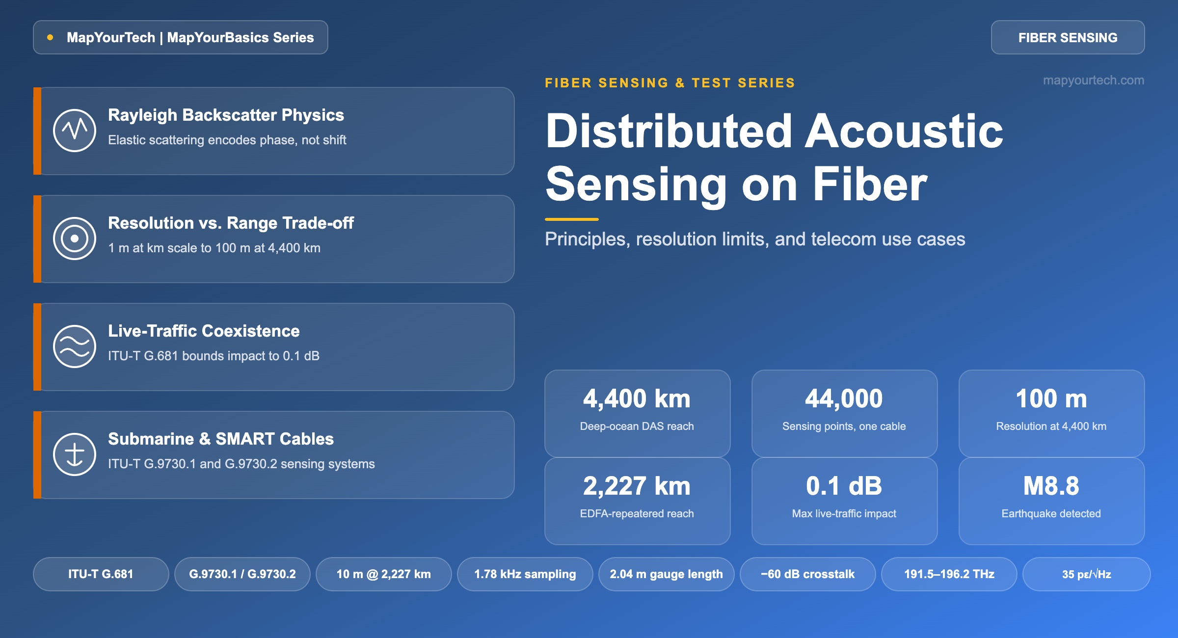
Distributed Acoustic Sensing on Fiber: Principles, Resolution, and Telecom Use Cases
How coherent Rayleigh backscatter turns an ordinary strand of deployed fiber into thousands of acoustic sensors, what actually limits spatial resolution and detection latency, and how operators now run sensing alongside live DWDM traffic under ITU-T G.681.
Introduction
A single strand of standard single-mode fiber, already carrying live 400G coherent DWDM channels, can also report a backhoe digging near the cable route, a footstep crossing a buried span, or a magnitude-8 earthquake rupturing four kilometers beneath the Pacific — using nothing more than the light already scattering back from imperfections frozen into the glass. That capability is Distributed Acoustic Sensing (DAS), and as of late 2025 it is no longer a laboratory curiosity bolted onto dedicated dark fiber. The International Telecommunication Union's standardization arm, ITU-T Study Group 15, approved Recommendation ITU-T G.681 in November 2025, defining exactly how a sensing signal can share a live terrestrial DWDM fiber with revenue traffic without degrading it. Distributed fiber sensing has moved from a niche oilfield and pipeline tool into a standards-track capability that telecom operators, cable landing station engineers, and network architects now have to understand.
DAS belongs to a broader family called Distributed Fiber Optic Sensing (DFOS), which also includes Brillouin-based distributed temperature and strain sensing and Raman-based distributed temperature sensing. What separates DAS from its siblings is the physical mechanism it exploits — elastic Rayleigh backscatter rather than the frequency-shifted Brillouin or Raman components — and the consequence of that choice: DAS measures dynamic strain at acoustic frequencies, from a few hertz to several kilohertz, at every point along the fiber simultaneously, with no active components buried in the ground or laid on the seabed.
This article works through the physics that makes Rayleigh backscatter usable as a phase-sensitive sensor, the interrogator architecture that converts that backscatter into a strain waterfall, the hard trade-off between spatial resolution and sensing range that governs every DAS deployment, and the specific mechanics of running a sensing signal alongside live telecom traffic under G.681. It closes with a deep-ocean case study — a 4,400 km operational Pacific telecom cable that recorded a magnitude-8.8 earthquake and its tsunami wave with 44,000 individual sensing points — because the numbers from that deployment say more about what DAS can and cannot do than any general description.
Scope note: This article is a sensitive topic overview only in the sense that it covers infrastructure security implications (third-party interference and intrusion detection). If your interest is in fiber optic security architecture more broadly, the Optical Return Loss guide and the undersea repeater reference cover the passive-layer fundamentals this article builds on.
1. Fundamentals of Fiber-Based Acoustic Sensing
Rayleigh Backscatter as the Sensing Mechanism
Every optical fiber ever drawn contains frozen-in, randomly distributed density and compositional fluctuations left over from the manufacturing process. These fluctuations elastically scatter a small fraction of any light passing through — Rayleigh scattering — in all directions, including straight back toward the source. This is the identical physical effect that a conventional Optical Time-Domain Reflectometer (OTDR) uses to build its attenuation trace: launch a pulse, measure the intensity of the returning backscatter as a function of time, and convert time into distance using the fiber's group index.
Rayleigh scattering is elastic — the scattered light retains the same optical frequency as the incident light, unlike Brillouin scattering, where the light interacts with acoustic phonons and returns shifted by roughly 11 GHz at 1550 nm in standard silica fiber, or Raman scattering, where the shift is far larger and governed by molecular vibrational modes. This distinction matters directly for sensing: Brillouin and Raman shifted returns encode absolute temperature and strain through a spectral shift, which is why Brillouin-based distributed sensors (BOTDR/BOTDA) and Raman-based distributed temperature sensing (DTS) exist as separate, complementary technologies. Rayleigh backscatter, having no systematic frequency shift, instead preserves a stable interference pattern between the thousands of individual scattering centers illuminated by a coherent pulse. Any physical disturbance — a vibration, an acoustic wave, a strain event — locally stretches or compresses that section of fiber, which shifts the optical path length between scatterers and rotates the phase of the interference pattern. Measuring that phase rotation, point by point along the fiber, is what DAS does.
This is a well-established relation in fiber optics, standard-specified in the sense that it derives from acoustic phonon physics rather than any vendor design. At the 1550 nm window, with an acoustic velocity VA of approximately 5,960 m/s in silica, the Brillouin shift is approximately 11 GHz. DAS interrogation instead operates on the unshifted Rayleigh component to preserve interferometric phase information rather than encoding a spectral shift.
- n — refractive index of the fiber core
- VA — acoustic velocity in the fiber material
- λ — optical wavelength of the interrogating signal
From OTDR to Phase-Sensitive OTDR
A conventional OTDR discards phase information entirely; it only cares about backscattered intensity averaged over many pulses, which is exactly what you want for a stable attenuation trace, and exactly what makes it useless for vibration sensing. Phase-sensitive OTDR (φ-OTDR, sometimes written phi-OTDR) instead uses a coherent, narrow-linewidth laser source, so that the interference between scattering centers within each resolved fiber segment produces a stable, repeatable speckle-like pattern from pulse to pulse — until something physically disturbs that segment of fiber, at which point the pattern shifts. Comparing successive traces reveals exactly where along the fiber a disturbance occurred and, from the rate and magnitude of the phase change, its acoustic signature.
The reference implementation used across most modern DAS systems is chirped-pulse φ-OTDR (CP-φOTDR), formalized in 2016. Rather than a plain rectangular pulse, the interrogator launches a linearly frequency-swept ("chirped") pulse and compresses it on receive, which gives intrinsic immunity to a known failure mode of earlier coherent-detection schemes called fading — points along the fiber where destructive interference happens to suppress the backscatter signal to near zero regardless of any real disturbance. CP-φOTDR uses direct (non-coherent) detection at the receiver, which keeps the interrogator hardware comparatively simple while retaining high sensitivity.
This is the standard engineering relation used across the phase-sensitive OTDR literature for direct-detection systems: the minimum resolvable distance is set by half the pulse width, converted to a length using the fiber's group index. A 100 ns pulse in fiber with n ≈ 1.468 resolves to roughly 10 meters. Coherent-detection systems decouple resolution from the pulse width and instead tie it to a separately chosen parameter, the gauge length, described below.
- c — speed of light in vacuum
- τ — pulse duration (or compressed pulse duration for chirped pulses)
- n — group refractive index of the fiber
Gauge Length: The Parameter That Actually Governs Sensitivity
In coherent-detection φ-OTDR systems, sensitivity to strain and spatial resolution are not the same thing, and conflating them is the most common conceptual error engineers new to DAS make. The system recovers the complex backscattered field at every point, then computes a phase difference between two points separated by a chosen baseline — the gauge length — to derive local strain rate. A short gauge length gives fine spatial resolution but weak signal, because the Rayleigh return from a short fiber segment is a small, noisy sample of the total scattering population. A long gauge length averages over more scatterers and produces a cleaner signal, at the cost of smearing closely spaced or highly localized events together. This trade-off is set in software or firmware, per deployment, independent of the physical pulse width — which is precisely why commercial interrogators let operators tune gauge length from tens of centimeters up to tens of meters depending on the application.
During a field deployment monitoring an urban parade route, a fiber-optic interrogation unit turned a 3.88 km fiber cable into a discrete sensor array with receivers spaced every 1.02 m, using a gauge length of 2.04 m and a temporal sampling rate of 2,500 Hz. That channel spacing was chosen specifically to sit below the spatial-aliasing threshold for the acoustic content of interest — footsteps, brass instruments, and crowd noise — while the short gauge length preserved fine positional discrimination across a densely packed urban environment. The system was remotely monitored over a standard 4G cellular link, illustrating how far DAS deployment logistics have moved from dedicated fiber-optic backhaul requirements.
Standards Framework
Distributed fiber sensing sat outside formal telecom standardization for most of its history, borrowing test procedures from oilfield and pipeline monitoring practice. That changed across 2024 and 2025 with four ITU-T Recommendations that, together, now define how DAS integrates into telecom infrastructure both on land and undersea.
| Recommendation | Title | Scope |
|---|---|---|
| ITU-T G.681 | Distributed fibre optic sensing system for terrestrial optical transmission systems | Interface parameters for running DFOS on live in-service DWDM fiber; approved November 2025 |
| ITU-T G.9730.1 | Dedicated scientific sensing submarine cable system | Purpose-built submarine sensing cables, independent of telecom traffic; approved August 2024 |
| ITU-T G.9730.2 | Scientific monitoring and reliable telecommunication (SMART) submarine cable systems | Sensors integrated into standard telecom submarine repeaters; approved August 2024 |
| ITU-T G.978 (3rd edition) | Characteristics of optical fibre submarine cables | Formally added "dedicated sensing submarine cable" as a recognized cable application category; approved May 2025 |
ITU-T G.681 is the one most directly relevant to terrestrial operators: it defines reference interface points (DFOS-Sb1 at the sensing head-end aggregate output, DFOS-Rb1 at the aggregate input), specifies in-band operation across the C and L bands per ITU-T G.694.1 frequency ranges (191.5–196.2 THz for the C-band), and out-of-band operation in defined S-band and U-band ranges (U-band starting at 1635 nm). It permits DFOS on the recognized transmission fiber types ITU-T G.652, G.654, and G.657. The Recommendation's central numerical constraint — covered in detail in the next section — caps the allowable degradation to co-existing DWDM traffic at 0.1 dB of required OSNR and receiver sensitivity increase for the specified unidirectional, counter-propagating configuration.
Takeaway: DAS works because Rayleigh backscatter is elastic and coherent, preserving a phase relationship that a chirped-pulse phase-sensitive OTDR can track over time. Spatial resolution in coherent-detection systems is set by the chosen gauge length, not directly by pulse width, which is why the same physical hardware can be reconfigured from centimeter-scale urban sensing to hundred-meter-scale deep-ocean seismic monitoring. As of November 2025, ITU-T G.681 gives this technology a formal standards home in terrestrial DWDM networks, alongside G.9730.1, G.9730.2, and the updated G.978 for submarine deployment.
2. Technical Architecture of a DAS Interrogator
The Interrogator Hardware Chain
A DAS interrogator is functionally a specialized coherent OTDR tuned for repeated, high-speed acquisition rather than single-shot attenuation profiling. The chain begins with a narrow-linewidth continuous-wave laser — often locked to an external reference for long-reach or high-precision deployments — followed by a pulse or chirp modulator that carves the interrogating waveform, an optional erbium-doped fiber amplifier (EDFA) booster stage, and a circulator or coupler that routes the outgoing pulse into the fiber under test while directing the returning backscatter to the receive path. On the receive side, direct-detection systems use a single photodiode and high-speed digitizer; coherent-detection systems mix the returning field with a local oscillator derived from the same source laser, recovering full amplitude and phase information, typically across two orthogonal polarization states to avoid polarization-induced signal fading. The digitized waveform then passes through an FPGA for real-time phase demodulation and a GPU or server-class processor for event classification, with results rendered as a distance-versus-time strain waterfall.
Direct-Detection vs. Coherent-Detection φ-OTDR
Direct-detection chirped-pulse systems remain attractive for cost-sensitive, single-parameter deployments — pipeline right-of-way monitoring, perimeter security — because they avoid the added complexity of a coherent receiver while still delivering meter-scale resolution. Coherent-detection systems recover the full complex field and are preferred where dynamic range, strain-rate accuracy, or long unamplified reach matter, because they extract more information per pulse and are more resilient to the signal-fading effects that plague simpler schemes. A dual-polarization coherent interrogator using orthogonal complementary Golay code pairs, tested over a 26 km standard single-mode fiber, demonstrated vibration detection and localization across a 475 Hz bandwidth with a distance-dependent sensitivity of roughly 15 nm peak-to-peak at 1 km and 40 nm peak-to-peak at 25 km — illustrating both the achievable precision and the expected sensitivity roll-off with distance that every DAS design has to budget for.
Known limitation — polarization and signal fading: Coherent-detection systems are vulnerable to polarization-induced fading, where the state of polarization of the returning backscatter happens to align poorly with the receiver's reference and the recovered signal drops out at specific points along the fiber, independent of any real event. Dual-polarization receivers and frequency-diverse chirped pulses are the two most common mitigations, and most commercial-grade interrogators built for telecom or submarine deployment now include one or both by default.
Coexistence With Live DWDM Traffic
The mechanism that makes G.681 workable is directional. In the specified unidirectional, counter-propagating configuration — the DFOS pulse traveling in the opposite direction to the DWDM payload channels on the same fiber — the standard limits the maximum allowed degradation to co-existing traffic to 0.1 dB of required OSNR increase and 0.1 dB of receiver sensitivity increase. That is a genuinely tight budget, deliberately so: it means an operator can activate sensing on a live, revenue-generating span without a measurable service impact. Co-propagating configurations, where the sensing pulse travels the same direction as the data channels, are a different story. G.681's own case study and simulation work (Appendix II) shows that co-propagating, high-peak-power DFOS pulses introduce severe nonlinear impairments — cross-phase modulation (XPM) and stimulated Raman scattering (SRS) tilt — onto the data channels, while counter-propagating pulses cause negligible XPM by comparison.
Design constraint: Co-propagating a high-peak-power DFOS pulse with live DWDM payload channels is not a safe default configuration. ITU-T G.681's own nonlinear-impairment analysis found severe XPM and SRS-driven tilt from this arrangement. Counter-propagating, out-of-band or carefully managed in-band operation is the configuration the standard actually qualifies for the 0.1 dB impact budget.
Real deployments confirm the power trade-off this constraint creates. In one long-reach submarine DAS demonstration described in the next section, the operators ran the DAS launch power at approximately −3 dBm to match the power of the co-resident data channels — more than 10 dB below the optimal standalone DAS launch power — which measurably weakened the sensing signal-to-noise ratio. The stated remedy is a bidirectional interrogation configuration, running two interrogator systems from each end of the cable, to recover the lost SNR without raising launch power beyond what live-traffic coexistence allows.
Takeaway: A DAS interrogator is a coherent OTDR built for repeated, high-speed sampling rather than single-shot fault location. Direct detection is simpler and adequate for many terrestrial applications; coherent, dual-polarization detection buys dynamic range and reach at added hardware cost. Running DAS on a live telecom fiber under ITU-T G.681 is possible with a tightly bounded 0.1 dB traffic impact, but only in the counter-propagating configuration the standard actually validates — co-propagation with high-peak pulses is a documented source of nonlinear impairment.
3. Design Considerations: Range, Resolution, and the Trade-off Between Them
The Resolution-Range Trade-off
Every DAS deployment sits somewhere on a curve between fine spatial resolution over a short reach and coarse resolution over a long reach, and that curve is not a marketing artifact — it follows directly from fiber attenuation. The interrogating pulse loses roughly 0.2 dB/km on the outbound path, and the Rayleigh backscatter itself is weak (a small, fixed fraction of the forward power) and loses a further 0.2 dB/km on the return, so total round-trip loss accumulates at close to 0.4 dB/km. Every additional kilometer of reach therefore costs signal-to-noise ratio, which the system has to recover either by widening the gauge length (accepting coarser resolution), extending signal averaging time (accepting lower update rate), or adding optical amplification along the path.
Chart data: urban parade-route DAS at 3.88 km range achieved 1.02 m channel spacing; a commercial pipeline-grade TGD-OFDR interrogator achieved approximately 1.8 m resolution at 80 km range; an EDFA-repeatered submarine DAS line achieved 10 m resolution over 2,227 km; a deep-ocean long-reach DAS system achieved 100 m resolution over 4,400 km.
| Approach | Demonstrated range | Spatial resolution | Source context |
|---|---|---|---|
| Unamplified direct-detection φ-OTDR, terrestrial | Tens of km, typical single-ended | Meter-scale | Standard telecom span budgets |
| Raman-assisted chirped-pulse φ-OTDR | Up to ~100 km | Meter-scale | Bidirectional first-order Raman amplification over 75 km SMF, low-cost setup characterized to 100 km |
| EDFA-repeatered subsea DAS | 2,227 km, 39 repeatered spans | 10 m | Alcatel Submarine Networks, Optics Letters 50(1), 25–28 |
| Long-reach deep-ocean DAS via HLLB loopback | 4,400 km operational cable | 100 m | Nokia Bell Labs / Leidos, 44,000 sensor points, described in Section 5 |
| Per-span interferometry (related but distinct technique) | Full transoceanic cable length | 50–100 km | Resolution set by repeater spacing; not true DAS but a complementary coarse-sensing method |
Extending Reach: Amplification Strategies
The two dominant reach-extension strategies mirror the two amplification families already familiar from long-haul DWDM design. Raman-assisted DAS injects a counter- or co-propagating Raman pump alongside the sensing pulse, providing distributed gain along the fiber itself rather than at discrete points — the same principle covered in the clean-fiber-zone commissioning practice for Raman-amplified transmission links, where launch conditions and reflectance budgets have to be controlled before the pump can run at full power. Applied to DAS, this approach has been characterized to approximately 100 km with comparatively low-cost interrogator hardware.
Discrete EDFA relay is the alternative, and it is the approach that scales furthest in demonstrated results: a 2024 field trial by Alcatel Submarine Networks pushed single-ended DAS interrogation through a 2,227 km line comprising 39 repeatered fiber spans, achieving 10 m spatial resolution, a 1.78 kHz sampling rate, and a strain resolution of 35 picostrain per root-hertz at the outermost span — with wavelength-multiplexed DAS channels addressed through add/drop multiplexers at less than −60 dB cross-talk between spans. That result shares its underlying amplifier and repeater technology directly with existing long-haul submarine cable repeater infrastructure, which is precisely the point: DAS reach extension does not require new undersea hardware, only new signal processing riding on infrastructure operators already deploy for data transport.
A metro operator monitoring a 35 km buried duct route for dig-before-damage alerting does not need meter-scale positional accuracy — an excavator or directional drill is a large, slow-moving disturbance spanning several meters of fiber regardless of gauge length. Selecting a gauge length of 5–10 m instead of 1 m trades away positional precision the application does not need in exchange for a meaningfully stronger, lower-noise signal, which in turn reduces false-positive alarms from ambient traffic vibration near the route. The same interrogator, redeployed on a data-center perimeter fence a few hundred meters long, would typically be reconfigured to a sub-meter gauge length, because footstep- and cut-scale events on a short route benefit from the finer localization and the shorter distance leaves ample SNR margin to spare.
Takeaway: Spatial resolution and sensing range trade against each other because both draw from the same finite signal-to-noise budget set by round-trip fiber attenuation. Raman-assisted amplification extends unrepeatered reach to roughly 100 km with modest hardware; discrete EDFA relay, sharing technology with standard submarine repeaters, has been demonstrated to 2,227 km at 10 m resolution. Choosing gauge length is an application decision, not a hardware limitation — it should match the physical scale of the events being monitored, not simply be minimized.
4. Implementation: Deploying DAS on Telecom Infrastructure
Dark Fiber vs. Live-Traffic Sensing
The simplest deployment model dedicates a spare, unlit fiber strand entirely to sensing, sidestepping every coexistence concern covered in Section 2 at the cost of tying up a strand that could otherwise generate transport revenue. That model made sense while DFOS lacked a formal interface specification for shared operation. With ITU-T G.681 now defining the counter-propagating, power-bounded configuration that keeps impact on live channels within 0.1 dB, operators increasingly favor running sensing on fiber that is simultaneously carrying commercial DWDM traffic, converting existing infrastructure into a sensing layer without a dedicated fiber build-out.
Terrestrial Use Cases
The single most cited terrestrial application is early threat detection for the fiber plant itself — commonly described as dig-before-damage monitoring. DAS distinguishes the acoustic signature of hand digging, mechanized excavation, directional drilling, and routine vehicle traffic near a buried route well before any of those activities reach the cable. A May 2026 industry paper from the Fiber Broadband Association framed this directly: distributed acoustic sensing lets operators detect digging, tampering, or environmental disturbance before fiber damage occurs, reducing outages and repair costs rather than only detecting them after the fact. Separate metropolitan network research on just-in-time fiber restoration reports detecting the acoustic precursors of cable damage — excavation, cable hauling in ducts, cable movement — with a five- to seven-minute lead time ahead of the actual fiber cut, which is enough of a window for automated systems to pre-stage protection switching or dispatch a field crew before an outage occurs rather than after.
Beyond damage prevention, the same buried or ducted fiber supports perimeter and data-center security (detecting fence climbing, cutting, and unauthorized access along the route), traffic monitoring on adjacent roadways by extracting vehicle traces from the strain waterfall using image-processing and deep-learning techniques, and rail corridor monitoring, tracking train position and detecting track anomalies to a resolution of a few tens of meters continuously along the monitored section — all from fiber that was originally installed purely for data transport.
Business model shift: The Fiber Broadband Association's May 2026 report on DFOS for fiber network operators names an emerging monetization path it calls Fiber Sensing as a Service (FSaaS) — operators selling threat-detection, structural-monitoring, and traffic-data feeds derived from fiber they have already deployed for connectivity, turning existing plant into a second, largely incremental revenue stream.
Submarine Use Cases
Undersea, DAS supports two distinct deployment models formalized by ITU-T G.9730.1 and G.9730.2. Dedicated scientific sensing submarine cable systems (G.9730.1) are purpose-built, separate from commercial telecom cables, and support chain, ring, horseshoe, or mesh topologies feeding data to shore-based collection and storage systems, typically for climate monitoring and disaster prediction using temperature, pressure, vibration, and salinity sensors. SMART cables (G.9730.2) instead embed discrete sensor sets — a temperature sensor, a pressure sensor, and a three-axis accelerometer, nominally one set per repeater span — directly into an otherwise conventional telecommunications submarine cable, so the same infrastructure carries commercial data traffic and scientific monitoring data simultaneously.
The MapYourTech reference on G.9730.1 and G.9730.2 covers the architectural detail of both standards. What DAS specifically adds on top of point sensors like SMART cable accelerometers is continuous spatial coverage along the entire cable rather than samples only at repeater locations — the difference explored in the case study in Section 5, where 44,000 individual sensing points along a single cable outperform the roughly 100 discrete accelerometer locations a SMART-cable-only deployment on the same route would provide.
Takeaway: Terrestrial DAS deployments center on protecting the fiber plant itself — dig-before-damage alerting with reported lead times of five to seven minutes ahead of a cut — while extending naturally into perimeter security, traffic monitoring, and rail corridor sensing on the same infrastructure. Submarine deployments split between dedicated scientific sensing cables (G.9730.1) and SMART cables that fold discrete sensors into standard telecom repeaters (G.9730.2), with long-reach DAS offering a third path: continuous coverage along an entire operational telecom cable rather than samples only at repeater locations.
5. Performance and Analysis: A Deep-Ocean Case Study
The clearest illustration of both DAS's reach and its detection latency comes from a 2025 field result reported by researchers at Nokia Bell Labs, Leidos, and collaborators, using a 4,400 km operational telecommunications submarine cable connecting California and Hawaii across the Pacific Ocean.
Scenario: The cable's route passes through water depths exceeding 4,000 m for more than 4,200 km of its length, comprises roughly 100 repeaters at a typical span length near 45 km, and — critically — cannot be reached by conventional near-shore DAS techniques, which stop at the first repeater. The team instead coupled a long-reach DAS system to the cable's high-loss loopback (HLLB) path, the same monitoring path submarine systems already use for line supervision, accepting a coupling loss of roughly 40 dB in exchange for access to the entire cable length.
Implementation: The interrogator combined a photonic integrated circuit, an FPGA, a streaming-capable GPU, and an NKT BASIK E15 laser locked to a vacuum reference cavity, launching dual-polarization waveforms with a 250 MHz sweep bandwidth. Because the system had to coexist with live data channels on the same fiber, its launch power was held to approximately −3 dBm — matching the data channel power and more than 10 dB below the optimal standalone DAS launch power. The output was filtered and decimated to roughly 16 Hz for storage, producing a manageable data rate of about 3 MB/s from a cable spanning 44,000 individual 100 m sensing segments.
Outcome: On the date of the event, the system recorded a magnitude-8.8 mega-thrust earthquake off the coast of Eastern Russia across the entire cable. Signal-to-noise ratio along the fiber ranged between roughly 15 dB and 5 dB depending on water depth and coupling conditions. P-wave arrivals were recorded at both shore stations — California at 386 seconds and Hawaii at 484 seconds after the event — with arrival times across the whole cable falling within two minutes of each other. Roughly seven hours later, the same array recorded the passage of a tsunami wave approximately 1,000 km offshore at a depth near 4,400 m, the first fiber-optic detection of a tsunami wave beyond the first repeater in the deep ocean, made visible through coherent stacking of fifty adjacent 100 m segments.
This result speaks directly to the "latency of detection" question that governs whether DAS is useful for early warning rather than only forensic analysis. The physical detection latency — how quickly the disturbance itself reaches a given point on the cable — is bounded by the propagation speed of the seismic wave through rock and water, on the order of several kilometers per second for P-waves, which is why arrival times across the 4,400 km cable clustered within two minutes of each other despite the cable's enormous length. The system's own processing latency, layered on top of that physical delay, is set by its decimated 16 Hz output stream: sub-second to low-second data availability once the wave physically arrives at a given fiber segment. That combination — near-instantaneous, continuous coverage along the entire cable versus the sparse, slower-reporting Deep-ocean Assessment and Reporting of Tsunamis (DART) buoy network that presently provides most deep-ocean tsunami warning coverage — is the practical case for treating existing submarine telecom cables as a latent, already-installed seismic and tsunami sensing network. With roughly 600 submarine cables currently in service worldwide, the same long-reach DAS technique applied broadly represents a very large expansion of deep-ocean monitoring coverage without laying a single new cable.
Chart data: urban parade-route DAS sampled at 2,500 Hz over 3.88 km; a commercial pipeline-grade interrogator sampled up to 5,000 Hz over an 80 km range; the EDFA-repeatered 2,227 km subsea line sampled at 1.78 kHz; the 4,400 km deep-ocean long-reach system decimated its output to approximately 16 Hz for storage and transmission efficiency.
Takeaway: The 4,400 km Pacific cable result demonstrates that long-reach DAS, coupled through a cable's existing high-loss loopback path, can turn an entire operational telecom cable into a 44,000-point seismic array without any new hardware in the water. Detection latency in this application is dominated by the physics of wave propagation, not by the sensing system, and the resulting continuous coverage materially exceeds what sparse buoy-based tsunami warning networks can offer over the same deep-ocean routes.
6. Comparison With Other Distributed and Point Sensing Technologies
DAS is one member of a small family of technologies that all use the same physical fiber differently. Choosing between them is a question of which measurand matters and at what update rate, not which technology is objectively superior.
| Technology | Backscatter mechanism | Primary measurand | Typical spatial resolution | Typical update rate |
|---|---|---|---|---|
| DAS (φ-OTDR) | Rayleigh, phase | Dynamic strain / acoustic vibration | Sub-meter to ~100 m, gauge-length dependent | Hz to several kHz |
| BOTDR / BOTDA | Brillouin, frequency shift | Static strain and temperature | Meter-scale over km-scale range | Seconds to minutes per full trace |
| Raman DTS | Raman, frequency shift | Temperature only | Meter-scale | Seconds to minutes per full trace |
| Discrete FBG arrays | Bragg reflection, wavelength shift | Point strain / temperature | Fixed at installed grating locations only | kHz-capable, but point-sampled |
DAS's advantage is genuine continuous spatial coverage at acoustic-frequency update rates — nothing else on this list resolves a footstep or a P-wave arrival at every meter of a cable in real time. Its challenge is that it measures relative strain rate, not an absolute physical quantity like temperature in degrees, which makes it excellent at detecting and locating events but comparatively poor at quantifying slow, steady-state conditions. BOTDR and Raman DTS invert that trade-off: slower update rates measured in minutes, but calibrated, absolute temperature and strain values that DAS alone cannot provide. In practice, the technologies are complementary rather than competing — a submarine SMART cable pairing DAS with the discrete temperature and pressure sensors defined in G.9730.2 gets continuous acoustic event detection from one and calibrated absolute environmental readings from the other, on the same cable.
Takeaway: DAS is the right tool when the question is where and when a dynamic event occurred along a fiber route; Brillouin- and Raman-based distributed sensors are the right tool when the question is what the absolute temperature or static strain is at a given point. Most mature deployments, particularly SMART submarine cables, use more than one technology on the same fiber rather than choosing a single winner.
7. Future Directions
ITU-T G.681 is explicitly described by its own drafting team as the first step toward a viable telecom DFOS ecosystem rather than a finished endpoint, and the immediate roadmap items are visible in current industry activity. The Fiber Broadband Association's Technology Committee, in its May 2026 paper, called out shared data standards and event-signature libraries as a near-term priority — without a common way to describe what a "digging" or "tampering" acoustic signature looks like across vendors, interoperability between different operators' DAS deployments and any shared threat-intelligence feed remains limited. Expect standardization pressure to move in that direction next, following the same pattern that gave the industry a common physical-layer interface in G.681.
On the submarine side, the newly approved G.9730.1 and G.9730.2 framework is only beginning to see field deployment. Trial and pilot SMART cable projects are underway on routes including the Southern Cross NEXT system between New Zealand and Australia, alongside separate national programs incorporating seismic and environmental sensors into planned cable landings. Long-reach DAS results like the 4,400 km Pacific case study in Section 5 point toward a specific, near-term research question: how far the HLLB-coupled, live-traffic-compatible approach can be pushed past 4,400 km, and whether it can eventually cover entire transoceanic routes at meaningfully better resolution than the 50–100 km granularity of per-span interferometry.
Artificial intelligence and machine learning are already the primary lever for making DAS data usable at scale — a single long-haul deployment can generate tens of thousands of simultaneous channels of high-rate strain data, far beyond what manual review can process, and pattern-recognition models for event classification are the subject of active published research aimed specifically at reducing false-positive alarm rates in perimeter security and threat-detection applications. As that classification layer matures alongside the physical-layer standards covered in this article, DAS is positioned to move from a specialist sensing tool into a default feature of new telecom fiber deployments, in the same way that OTDR testing moved from a specialist instrument to a routine part of every DWDM system commissioning workflow.
Takeaway: The standards foundation for telecom DAS is now in place — G.681 for terrestrial coexistence, G.9730.1 and G.9730.2 for submarine deployment — which shifts the open questions from "can this share a live fiber" toward interoperable event classification, further reach extension past today's demonstrated 4,400 km, and the business models needed to turn a sensing capability that already exists on deployed fiber into an operational and commercial reality.
References
- ITU-T G.681 — Distributed fibre optic sensing system for terrestrial optical transmission systems, ITU-T Study Group 15.
- ITU-T G.9730.1 — Dedicated scientific sensing submarine cable system, ITU-T Study Group 15.
- ITU-T G.9730.2 — Scientific monitoring and reliable telecommunication submarine cable systems, ITU-T Study Group 15.
- ITU-T G.978 — Characteristics of optical fibre submarine cables, ITU-T Study Group 15.
- Optica Publishing Group, Journal of Optical Communications and Networking — Distributed fiber sensor network using telecom cables as sensing media: technology advancements and applications.
Sanjay Yadav, "Optical Network Communications: An Engineer's Perspective" — Bridge the Gap Between Theory and Practice in Optical Networking.
Related Articles on MapYourTech






