
MapYourTech | MapYourBasics Series
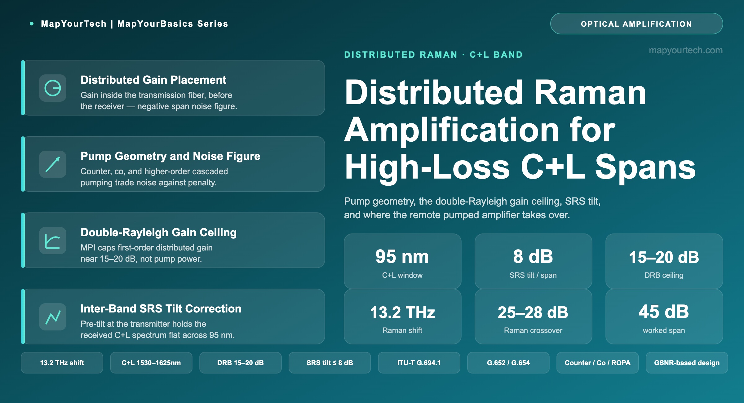
Distributed Raman Amplification for High-Loss C+L Band Spans
Where the EDFA-only budget runs out, distributed Raman buys back OSNR inside the transmission fiber. This is the pump geometry, the gain ceiling that bounds it, and the point where a remote pumped amplifier takes over.
Tomorrow's networks are built on today's innovations.
Introduction
An EDFA restores span loss at a point: the signal reaches the amplifier weak, and the amplifier lifts it in a metre of erbium-doped fiber. A distributed Raman amplifier does something different — it makes the transmission fiber itself the gain medium, so amplification happens along the last tens of kilometres of the span before the signal ever reaches the receiver. The signal is never allowed to fall as deep into the noise, which is why Raman improves the optical signal-to-noise ratio (OSNR) an EDFA-only span cannot reach.
On a C+L band system the stakes are higher and the interactions are sharper. The combined C+L window spans roughly 95 nm, wide enough that the pump wavelengths, the two signal bands, and the fiber's own nonlinear response all interact. This article works through distributed Raman on high-loss C+L spans: what it adds to the budget, how pump geometry sets its noise performance, the double-Rayleigh mechanism that caps its gain, the stimulated Raman scattering (SRS) tilt that couples the two bands, and where the remote optically pumped amplifier (ROPA) takes over for the longest unrepeatered crossings. The treatment is vendor-neutral — the mechanisms and boundaries hold across implementations, and the numbers are drawn from the standards and measurement literature rather than any one product line.
Where Raman Enters the Link Budget
Distributed Raman earns its place at the loss level where an EDFA-only design stops closing. On a chain of amplified spans, receiver OSNR falls as noise from each amplifier accumulates; the standard first-order relation is that delivered OSNR drops by 10·log₁₀(N) across N identical spans, so four spans cost 6 dB relative to one. On a single very long span, the loss that must be recovered at one amplifier drives the noise figure penalty directly. Once span loss climbs past roughly 25–28 dB, the EDFA budget alone often no longer delivers enough receiver OSNR for the target modulation format, and distributed Raman becomes the way to buy it back. This threshold is a working design signal, not a hard standard limit — the exact crossover depends on fiber type, channel count, and the required generalized signal-to-noise ratio (GSNR) of the transmission mode.
The mechanism behind the OSNR gain is placement. Because the Raman pump amplifies the signal while it is still in the transmission fiber, the effective noise figure of the span can be driven negative — the distributed gain more than offsets the noise it adds over the amplified length. Measurement studies put the equivalent noise figure into negative territory once on/off Raman gain exceeds about 10 dB. That is a result an EDFA, a discrete amplifier that lifts an already-weak signal, cannot produce. The relationship between OSNR margin and the modulation format it enables is set out in the MapYourTech treatment of OSNR fundamentals, and the point at which amplifier choice trades cost against OSNR is covered in optical network topology basics.
Raman is added on the spans where the budget does not close, not everywhere. It carries a cost — high-power pump lasers, tighter connector and reflection discipline on the line-side ports, and safety interlocks — so the design reserves it for the spans that need it. The connector loss budget analysis explains why APC line-side connectors are mandatory once Raman pumps are present: even small back-reflections degrade OSNR and can destabilize the pump.
Pump Geometry: Counter, Co, and Higher-Order
A distributed Raman amplifier is defined first by where its pump launches and in which direction. The pump is set roughly 100 nm below the signal band — the frequency offset for peak Raman gain in silica is about 13.2 THz — so a C-band signal near 1550 nm is amplified by a pump near 1450 nm. Three arrangements dominate practical design, and they trade noise performance against nonlinear penalty.
Counter-Propagating Pump
The counter-pump launches from the downstream (receive) end and travels back toward the transmitter. Its gain is concentrated in the last part of the span, exactly where the signal is weakest, which is why counter-pumping gives the best noise figure and is the default first choice. Because the pump and signal travel in opposite directions, pump intensity noise averages out over the transit and does not transfer strongly onto the signal. Counter-pumping is the arrangement most C+L high-loss spans start from.
Co-Propagating Pump
The co-pump launches from the transmit end alongside the signal. It raises signal power early in the span, which lowers the effective launch-to-first-gain excursion and reduces some nonlinear penalty, but it couples pump relative intensity noise (RIN) directly onto the signal because both travel together. Co-pumping is added to a counter-pump — the co+counter configuration — when a single counter-pump cannot supply the gain the span needs, and it demands low-RIN pump sources to avoid trading OSNR back away.
Higher-Order and Cascaded Pumping
A first-order pump deposits its energy where it enters the fiber, so a counter-pump's gain peaks near the receive end. A higher-order, or cascaded, pump adds a shorter-wavelength pump that first amplifies the primary pump deeper inside the span, pushing the gain region further from the launch point and flattening the distribution along the fiber. This lowers the equivalent noise figure further and is what makes the longest unrepeatered spans reach — but, as the next section shows, it raises the double-Rayleigh penalty at the same time, so it is a controlled trade rather than a free improvement.
Figure 1: Pump geometry sets where Raman gain lands along the span. Counter-pumping concentrates gain near the receive end for the best noise figure; adding a co-pump raises total gain at the cost of RIN transfer; cascaded higher-order pumping pushes the gain region deeper for the lowest noise figure and the highest double-Rayleigh penalty.
The Double-Rayleigh Gain Ceiling
Distributed Raman gain does not scale without bound, and the limit is not pump power — it is double-Rayleigh backscatter (DRB). A small fraction of the signal is Rayleigh-scattered backward as it travels the fiber; a fraction of that is scattered a second time and rejoins the signal, now delayed and incoherent. Because both scattering events happen inside the distributed gain region, this doubly-scattered light is amplified along with the signal, and its power grows roughly as the square of the on/off gain. The result is multipath interference (MPI), which appears as a noise floor at the receiver after the beat on the photodiode.
The practical consequence is a ceiling. For first-order distributed Raman in the transmission fiber, DRB-induced MPI becomes the binding limit once on/off gain exceeds roughly 15–20 dB — beyond that, adding pump power raises MPI faster than it raises useful OSNR. Measurement studies place the point where DRB begins to bound the achievable noise figure at about 20 dB of on/off gain, with the lowest equivalent noise figure reached near 33 dB only under higher-order pumping that pays a rising DRB penalty to get there. This is why distributed Raman is paired with an EDFA rather than pushed to very high gain alone: the Raman stage supplies the distributed OSNR benefit up to its DRB ceiling, and the EDFA supplies the remaining lumped gain where MPI is not a factor.
DOUBLE-RAYLEIGH MPI SCALING
PDRB ∝ Gon/off2
The multipath-interference power from double-Rayleigh backscatter scales with the square of the on/off Raman gain. Doubling on/off gain in linear terms raises DRB power roughly fourfold, which is why the MPI penalty climbs steeply and sets a practical gain ceiling near 15–20 dB for first-order distributed pumping.
Figure 2: Illustrative trend — as on/off Raman gain increases, useful OSNR benefit rises with diminishing returns while the double-Rayleigh MPI penalty rises faster, crossing into the region where added gain no longer improves delivered signal quality. Curve shapes are schematic; the crossover region for first-order distributed pumping sits near 15–20 dB.
| On/off gain | On/off gain (dB) | Useful OSNR benefit (dB) | DRB MPI penalty (dB) |
|---|---|---|---|
| Low | 5 | 4.0 | 0.1 |
| Moderate | 10 | 7.5 | 0.4 |
| High | 15 | 10.0 | 1.2 |
| Very high | 20 | 11.5 | 3.0 |
| Extreme | 25 | 12.3 | 6.5 |
Takeaway: Distributed Raman gain is capped by double-Rayleigh backscatter, not pump power. First-order distributed pumping runs into the MPI ceiling near 15–20 dB on/off gain; pushing past it needs higher-order pumping, which lowers noise figure but raises the DRB penalty it is fighting. Design to the DRB ceiling and let an EDFA carry the rest of the gain.
C+L Specifics: SRS Tilt and Band Interaction
Everything above applies to a single band. C+L operation adds a coupling that does not exist in a C-only system: the two signal bands transfer power to each other through inter-channel stimulated Raman scattering (ISRS). SRS is the same physical process the Raman pump exploits, but here the signal channels themselves act as pumps and depletion targets. Power transfers from the shorter-wavelength C-band channels (higher frequency) to the longer-wavelength L-band channels (lower frequency): the C-band is depleted and the L-band receives Raman gain. Across the roughly 95 nm C+L window, this produces a spectral power tilt of up to about 8 dB per fiber span if left uncorrected.
This tilt is not a defect to be eliminated but a mechanism to be managed, and it interacts with the Raman pump design directly. The pump wavelengths must be planned so the pump-to-signal Raman gain covers both bands without the pumps themselves worsening the inter-band tilt, and the launch power profile is pre-tilted at the transmitter so that after ISRS acts over the span, the received spectrum arrives flat. The pump plan also has to avoid four-wave-mixing interference between the pump wavelengths and the service channels — a real constraint on which fibers and which pump wavelengths can be combined. The mechanism, the tilt magnitude, and the equalization requirement are developed in the MapYourTech reference on the basics of C+L band DWDM systems.
Because ISRS makes the two bands interdependent, the quality metric that matters is no longer per-band OSNR alone. The generalized signal-to-noise ratio (GSNR) folds ASE noise, nonlinear interference, and the ISRS-driven power redistribution into a single figure the transmission mode is designed against. A C+L design that optimizes the C-band in isolation will mis-predict the L-band, which is why wideband planning tools solve the launch power profile across both bands together. The distinction between linear OSNR and GSNR, and why it drives 400G-and-above reach, is the subject of the questions on Raman amplifiers reference and the broader Raman amplifier working-principle explainer.
On a C+L span, set the pre-tilt and per-band launch power against the ISRS profile, not against a flat target. The C-band is depleted and the L-band is amplified by the signal's own Raman interaction, so a spectrum launched flat arrives tilted by up to 8 dB. Correct for it at the transmitter and verify the received profile with an optical spectrum analyzer during commissioning.
Extreme-Loss Spans and the Remote Pumped Amplifier
Distributed Raman closes spans an EDFA-only design cannot, but it too has a reach limit set by the DRB ceiling and by how far a counter-pump's gain can usefully penetrate the fiber. For the longest unrepeatered crossings — a stretch of water, a route with no site for mid-span electronics — the next stage is the remote optically pumped amplifier (ROPA). A ROPA is an erbium-doped fiber section spliced into the deployed line fiber, tens of kilometres out from the terminal, with no active electronics at that point. It is pumped remotely: high pump power launched from the terminal travels down the fiber and energizes the erbium section, which provides lumped gain at a location where no equipment could otherwise be powered or maintained.
The combination — distributed Raman plus a remote erbium section — is what pushes single-span unrepeatered reach into the range beyond what either technique reaches alone. Published unrepeatered demonstrations using distributed Raman with remote amplification have carried multi-terabit aggregate capacity over spans well past 250 km, and research links combining these techniques have reached span losses in the region of 80–90 dB. The exact budget depends on where the ROPA erbium section sits along the span, because its position sets both how much remote pump power reaches it and how much signal gain it delivers before the receive terminal. That positioning is a per-route engineering decision, not a fixed catalog figure.
ROPA is an extreme-loss tool, reserved for spans where distributed Raman alone cannot close the budget and no mid-span site exists. It adds no active electronics in the field — only a passive erbium section and the fiber — which is precisely its value on submarine and remote terrestrial routes. On a standard high-loss terrestrial span, the counter-pump and, if needed, a co-pump usually close the budget without it.
Practical Example — Closing a 45 dB C+L Span
Consider a single C+L span on standard single-mode fiber (ITU-T G.652) presenting 45 dB of physical loss — well past where an EDFA-only design closes for a 400G-class transmission mode. The design proceeds in the order the mechanisms impose.
Scenario. One span, G.652 fiber, 45 dB physical loss, C+L loading, target a 400G DP-16QAM-class mode that needs roughly 22–24 dB receiver OSNR including margin.
Step 1 — counter-pump first. A counter-propagating distributed Raman stage supplies on/off gain in the 12–17 dB range on G.652, kept below the double-Rayleigh ceiling. Presented to the downstream EDFA, the span looks like its physical loss minus the measured Raman gain: 45 dB of physical loss with, say, 15 dB of measured Raman gain presents 30 dB to the amplifier chain. The EDFA recovers the remainder as lumped gain, where MPI is not a factor.
Step 2 — add a co-pump only if needed. If the counter-pump alone leaves the receiver OSNR short of the 22–24 dB target, a co-pump is added to raise total distributed gain and lift signal power earlier in the span. This buys OSNR but requires a low-RIN pump source, because co-pump intensity noise transfers onto the signal.
Step 3 — pre-tilt for ISRS. Because the span carries both bands, the launch profile is pre-tilted so that after the up-to-8 dB ISRS transfer from C to L acts across the span, the received spectrum arrives flat. The pump wavelengths are chosen to cover both bands and to avoid four-wave-mixing interference with the service channels.
Outcome. The counter-pump plus EDFA closes the 45 dB span for the target mode with the pre-tilt holding the received C+L spectrum flat; the co-pump is held in reserve for the case where the counter-pump margin is thin. A span at 55–60 dB or beyond, with no mid-span site, is where the design would cross into ROPA territory. These gain figures are representative of G.652 distributed Raman practice; the binding numbers for any real route come from a wideband planning tool run against the measured fiber and loss, as covered in the DWDM system commissioning checklist and the reach analysis in the IP over DWDM architecture walkthrough.
Design Limitations and Boundaries
Distributed Raman is not a free extension of reach, and its boundaries are as important as its capability. The double-Rayleigh ceiling caps first-order distributed gain near 15–20 dB; higher-order pumping lowers noise figure but raises the MPI penalty it is fighting, so it extends reach only where the design accepts the added DRB. Pump power is a real cost and a real hazard — Raman stages run pump lasers from several hundred milliwatts into the multi-watt range, which mandates automatic laser shutdown and automatic power reduction interlocks and forbids field work on live fiber. Connector and reflection discipline tightens: line-side ports must be APC, because back-reflection both degrades OSNR and can destabilize a high-power pump.
On C+L specifically, the SRS tilt couples the bands so tightly that the design cannot treat them independently — a single-band optimization mis-predicts the other band, and the pump plan must avoid four-wave-mixing interference across the wide window. None of these are reasons to avoid distributed Raman; they are the constraints that make it an engineered stage rather than a switch to flip. The correct posture is to exhaust the integrated Raman capability of the line system first, add co-pumping where the counter-pump falls short, and reserve ROPA for the extreme-loss spans where no other option closes the budget.
Takeaway: Distributed Raman extends C+L reach by making the fiber the gain medium, but every gain it buys is bounded — by double-Rayleigh MPI, by pump-safety limits, and on C+L by the inter-band SRS tilt. Design counter-pump first, add co-pump where needed, correct the ISRS tilt at the transmitter, and cross into ROPA only for the extreme-loss spans that have no mid-span site.
Conclusion
Distributed Raman amplification changes where gain happens: instead of lifting a weak signal at a point, it amplifies the signal inside the transmission fiber before the receiver ever sees it, which is the OSNR advantage an EDFA cannot match. On high-loss C+L spans that advantage is what turns an infeasible budget into a working one — but it is bounded on every side, by the double-Rayleigh ceiling that caps distributed gain, by the pump-safety envelope, and by the inter-band SRS tilt that makes the two bands a single coupled system. The engineering is in respecting those boundaries: counter-pump for the best noise figure, co-pump where the budget still falls short, wideband pre-tilt to hold the C+L spectrum flat, and the remote pumped amplifier held in reserve for the crossings nothing else can close. As wideband systems push past C+L toward S-band and beyond, the same mechanisms scale up in importance, and the design discipline that manages them on today's C+L spans is what the next window will be built on.
References
- ITU-T G.694.1 — Spectral grids for WDM applications: DWDM frequency grid, ITU-T Study Group 15.
- ITU-T G.652 / G.654 — Characteristics of single-mode optical fibre and cable, ITU-T Study Group 15.
- D. Semrau, R. I. Killey, P. Bayvel — The Gaussian Noise Model in the Presence of Inter-Channel Stimulated Raman Scattering, Journal of Lightwave Technology.
- T. Hoshida et al. — Ultrawideband Systems and Networks: Beyond C+L-Band, Proceedings of the IEEE.
- M. Cantono et al. — Opportunities and Challenges of C+L Transmission Systems, Journal of Lightwave Technology.
Sanjay Yadav, "Optical Network Communications: An Engineer's Perspective" — Bridge the Gap Between Theory and Practice in Optical Networking.
Related Articles on MapYourTech






