
Branching Unit Powering Reconfiguration and Fault Isolation
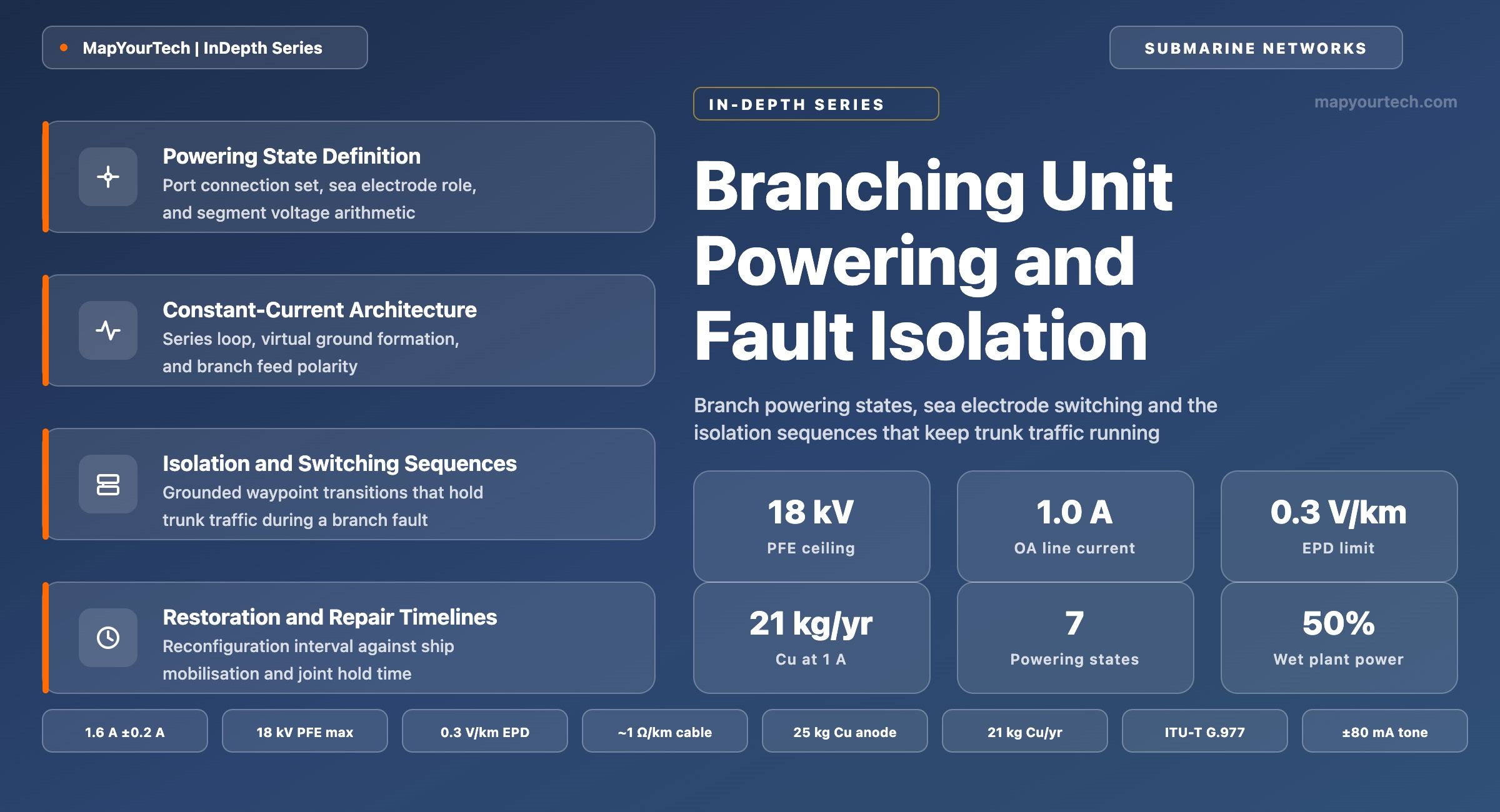
Branch powering states, sea electrode switching, and the isolation sequences that keep trunk traffic running while a branch is grounded, recovered and repaired.
Topology decides what fails together; equipment decides how often.
What You Will Learn
- Define a branching unit powering state as a connection set across three cable ports and one sea electrode, using the port anatomy of Figure 1.
- Separate the three in-service states from the three isolation states and the single grounded state that every transition passes through, per Table 6.
- Build a powering voltage budget from cable resistance near 1.0 Ω/km, an earth potential difference of 0.1 V/km and the 18 kV ceiling of present power feeding equipment.
- Quantify sea electrode consumption from Faraday's law, which gives about 21 kg of copper per year of positive feeding at 1.0 A against an electrode mass near 25 kg.
- Place the virtual ground of a powering segment on a shunt fault by adjusting two power feeding voltages of opposite polarity, and read the result from Figure 2.
- Order a reconfiguration sequence so no relay opens or closes under load, using the current-injection and optical-command control paths of Section 8.
- Convert a direct-current resistance reading into a shunt fault distance, and select the electroding tone at ±80 mA in service or ±160 mA out of service.
- Select between a star, fishbone and branch-on-branch powering plan against the reconfiguration complexity each one carries, using the comparison of Section 11.
1. Introduction
A trunk-and-branch submarine cable carries its electrical power on a single copper conductor per cable, fed as a stabilized direct current from power feeding equipment (PFE) in the terminal stations, with the circuit closed through seawater and earth. The branching unit (BU) sits at the junction of three cable sections and carries a sea electrode that establishes the return path of the power feeding current through the sea (standard-specified, ITU-T G.972 definition 4005 for the branching unit sea electrode). Every powering decision on that system reduces to one question: which of the three cable conductors are joined to each other inside the BU, and which one is joined to the electrode.
That question has a different answer before and after a fault. Under normal operation a fishbone system might feed the trunk straight through two branching units while each branch terminates on its own local electrode, drawing current from a branch station PFE. When a cable is damaged and the conductor is exposed to seawater, the cable acquires a hard ground at the damage point. The powering segment between that shunt fault and the nearest electrode now has ground at both ends, no current path, and no powered repeaters, so optical transmission through that segment ends even though the fibres in the surviving segments are intact. The power feeding architecture decides how much of the system goes dark with it.
Switchable branching units change that answer. A modern BU holds an array of high-voltage relays between the three cable power ports and the local sea ground, so the powering architecture can be reconfigured in service rather than requiring the whole system to be depowered for a repair. Reconfiguring the flanking branching units moves the electrode termination away from the isolated stretch, lets one PFE feed through the unit toward a station on the far side, and returns the depowered repeaters to service before any ship reaches the fault. On the same hardware, three further states ground individual ports so a cable section can be handled safely on deck.
The current and voltage numbers set the operating envelope. Optical amplifier systems run line currents near 1.0 A with a tolerance around ±0.3 A, against 1.6 A ±0.2 A in the earlier regenerative generation, and deployed repeatered systems today sit broadly in the 0.5–1.5 A range (measured practice across deployed transpacific systems). Maximum PFE output voltage was typically limited to 8 kV on transpacific systems before 2000 and reaches 18 kV in present equipment, which is what makes single-end feeding of a full-length transoceanic system possible after a fault (vendor capability, current PFE generation). A shunt fault on a charged 6,000 km cable discharges through the fault, and peak surge current at the fault can exceed 100 A; submerged plant surge protection is designed to bypass more than 200 A for long pulses and 450 A at 15 kV for short pulses (measured design values for repeater and BU protection circuits).
Two constraints then shape every sequence in this article. The first is electrochemical. The branch segment PFE must feed negative toward the BU sea electrode, because positive feeding drives electrolysis at the electrode and removes copper from it. Faraday's law puts that loss at roughly 21 kg per year of continuous positive feeding at 1.0 A, against a BU sea electrode mass of about 25 kg, so positive feeding toward a BU is held to under one year of accumulated time across the whole system life, temporary repair feeding included. The second is electrical. Relay contacts inside the BU should not open or close while carrying load. Every state transition therefore passes through the grounded state so the cable discharges before new conductor connections are made, and the reconfiguration sequence is designed so no relay is hot switched.
This article covers the electrical side of the branching unit: the powering state set, the arithmetic that bounds each state, the control paths that command a transition, and the isolation sequences used for shunt fault restoration, branch isolation and repair grounding. The optical side of the same housing, covering full fibre drop, fixed and reconfigurable add/drop, and fibre pair switching, is treated separately in the branching unit type overview, and the terminal-side equipment appears in the wet plant and dry plant boundary. Constant-voltage powering for scientific observatory cables enters only in Section 11, as a comparison against the constant-current telecom case.
2. Branching Unit Powering State Definition and Port Terms
A branching unit powering state is the set of electrical connections held inside the branching unit at one moment between its three cable power conductors and its sea electrode. Each conductor is either joined to another conductor, joined to the electrode, or isolated. The state is a discrete connection map with no units, and it is commanded, latched and reported as one item.
Figure 1 gives the anatomy. Three cable ports enter the pressure vessel, one from each direction of the trunk and one from the branch. A fourth terminal leaves the housing to the sea electrode, which is the local termination of a powering segment and the point at which the feeding current re-enters the sea. The high-voltage switch matrix between them holds the relays that make and break those connections. Nothing in this picture is optical: the same housing splices fibre pairs on a separate path, and the powering state can change without any fibre pair moving.
Read the Full Analysis with Premium
The remaining 88% of this article — the design numbers, trade-offs and field guidance — is part of MapYourTech Premium, along with the full premium library, courses and professional tools.
You May Also Like

-
Premium
-
August 22, 2026

-
Premium
-
August 22, 2026
-
Premium
-
August 22, 2026