
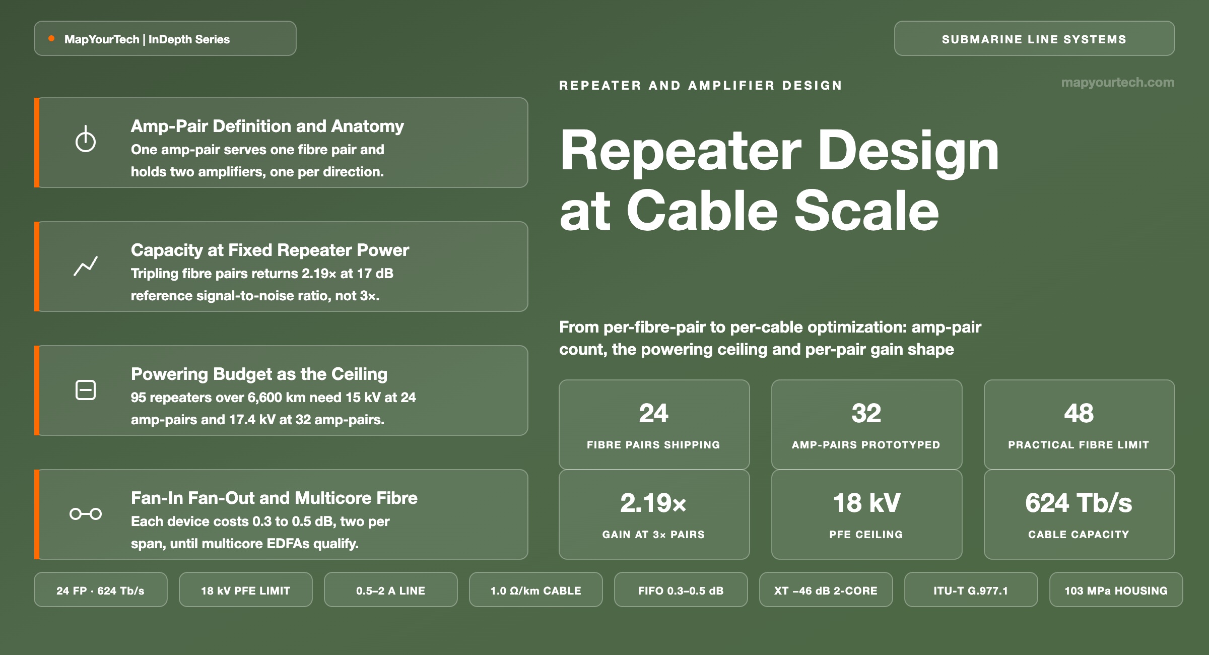
Repeater Design from Per-Fibre-Pair to Per-Cable Optimization
Amp-pair counts supporting roughly 24 fibre pairs today with 32 and 48 in view, fan-in fan-out components for multicore fibre, and the per-fibre-pair gain shape requirement every design still has to meet over transoceanic distance.
Pump power converts into gain, tilt and heat, in that order.
What You Will Learn
- Define the amp-pair against the fibre pair, the core pair and the pump unit, and read the anatomy of a shared-pump amp-pair in Figure 1.
- Quantify why tripling fibre-pair count at fixed repeater pump power multiplies cable capacity by 2.19× at 17 dB reference SNR but only 1.83× at 10 dB.
- Build the powering budget in Section 6 that puts a 24 amp-pair transatlantic repeater chain near 15 kV and a 48 amp-pair chain above 21 kV.
- Place gain flattening filters, gain tilt equalizers and shape compensation filters against the 42 dB tilt a 0.5 dB span-loss error accumulates over 120 amplifiers.
- Convert a 0.3 dB fan-in fan-out insertion loss into an effective span attenuation of 0.167 dB/km and the repeater count that follows.
- Anchor the −46 dB two-core crosstalk figure to a 0.1 dB signal-to-noise ratio penalty across 100 spans using the crosstalk expression in Section 8.
- Compare deployed and announced systems in Table 5, from 12 fibre pairs at 250 Tb/s to 24 fibre pairs above 624 Tb/s.
- Select between higher single-core fibre-pair counts and multicore fibre using the four-criterion comparison of Section 10 and the decision tree in Figure 11.
1. Introduction
A repeater housing is about 30 cm in outer diameter and about 70 cm of rigid length in the standard design, because those two numbers are what a linear cable engine and a cable-ship sheave will accept at laying speed (component figure, submarine plant engineering practice). Everything that has happened to submarine amplifier design over the last six years has happened inside that envelope. The amplifier count went from eight pairs to twenty-four, the industry moved an extended housing of roughly 90 cm into production to hold them, and the pump lasers stopped belonging to individual fibre pairs. None of that changed the tube.
The design rule that broke first was fibre-pair independence. For two decades a submarine repeater contained one self-contained amplifier pair per fibre pair, each with its own pump lasers, so that a failure anywhere in one pair could not reach another. That rule was worth its cost when a cable carried four to eight fibre pairs and each pair was engineered to the highest capacity the physics allowed. It stopped being worth its cost when 980 nm pump lasers reached 800 mW of output and a single amplifier could no longer usefully absorb one pump's worth of power without pushing its fibre pair past the nonlinear threshold. At that point the pump power in the repeater was worth more spread across many fibre pairs than concentrated in a few, and cable operators agreed to give up fibre-pair independence in exchange for pump sharing.
The consequence is the design change this article is about: submarine repeater design now optimizes the cable, not the fibre pair. Capacity per fibre pair went down. Capacity per cable went up. Effective area requirements relaxed from 150 µm² to 110 µm² and 80 µm², because a fibre operating well below the nonlinear threshold does not need a large effective area to keep nonlinear interference in check, and the cheaper fibre bought more parallel paths for the same money. Repeater spacing lengthened from the 50 to 60 km typical of high-power designs toward 70 to 80 km, because relaxing the signal-to-noise ratio requirement per fibre allows fewer amplifiers on the route. The number that matters to a cable owner became total cable capacity divided by total cost, and the number that binds it became the electrical power the cable can carry.
Twenty-four amp-pairs is where the production repeater sits today. The first operational 24 fibre-pair repeatered system, Unitirreno, entered service across 1,156 km of the Tyrrhenian Sea with more than 26 Tb/s available on each of its 24 trunk pairs and more than 624 Tb/s of total design capacity (vendor figures, ASN). Meta has stated 24 fibre-pair technology for Project Waterworth and for the 8,000 km Candle system, quoting 570 Tb/s on the latter (vendor and operator figures, Meta). Thirty-two amp-pairs exists as an announced repeater prototype. Forty-eight is on published roadmaps and is where the arithmetic starts to fight back, because the repeater voltage drop scales with amp-pair count and the power feeding equipment voltage does not scale with anything.
Two component-level changes sit behind the next step. Multicore fibre puts two or four cores inside a standard 125 µm cladding, which multiplies core count without touching the cable's outer diameter — and because today's repeater amplifies single cores, each core has to be separated out and recombined at every repeater by a fan-in fan-out device that adds roughly 0.3 to 0.5 dB of insertion loss twice per span. Integrated multicore erbium-doped fibre amplifiers would remove those devices, at the cost of holding an equal gain shape across cores in one doped fibre. That last point is where the article converges: whatever the spatial architecture, every fibre pair still has to arrive at the far terminal with a gain shape flat enough that all channels meet their signal-to-noise ratio target after 150 or more cascaded amplifiers. The gain shape requirement is the constraint that has survived every architecture change, and it is the one that decides which of the scaling paths is buildable.
This article covers repeater-side scaling: amp-pair count, pump sharing, the powering budget that bounds both, the gain equalization chain, and the component changes multicore fibre imposes. Wet-plant mechanical design, branching unit architecture and terminal equipment are treated only where they set a boundary on the repeater.
2. Amp-Pair Definition and Repeater Constituent Terms
An amp-pair is the amplification building block of a submarine repeater: two erbium-doped fibre amplifiers, one for each direction of a fibre pair, packaged together with a shared pump supply, a gain flattening filter in each path and a loopback monitoring tap. An amp-pair count states how many fibre pairs a repeater can serve.
The two amplifiers in an amp-pair are optically independent. Light travelling from terminal A to terminal B never enters the amplifier serving the return direction, and the gain, output power and noise figure of each are specified separately. What they share is electrical and pump infrastructure: the drive electronics, the control loop, and — since pump sharing became standard — a pool of 980 nm pump lasers whose combined output is split across several amp-pairs at once.
Read the Full Analysis with Premium
The remaining 88% of this article — the design numbers, trade-offs and field guidance — is part of MapYourTech Premium, along with the full premium library, courses and professional tools.
You May Also Like

-
Premium
-
August 22, 2026

-
Premium
-
August 22, 2026
-
Premium
-
August 22, 2026