
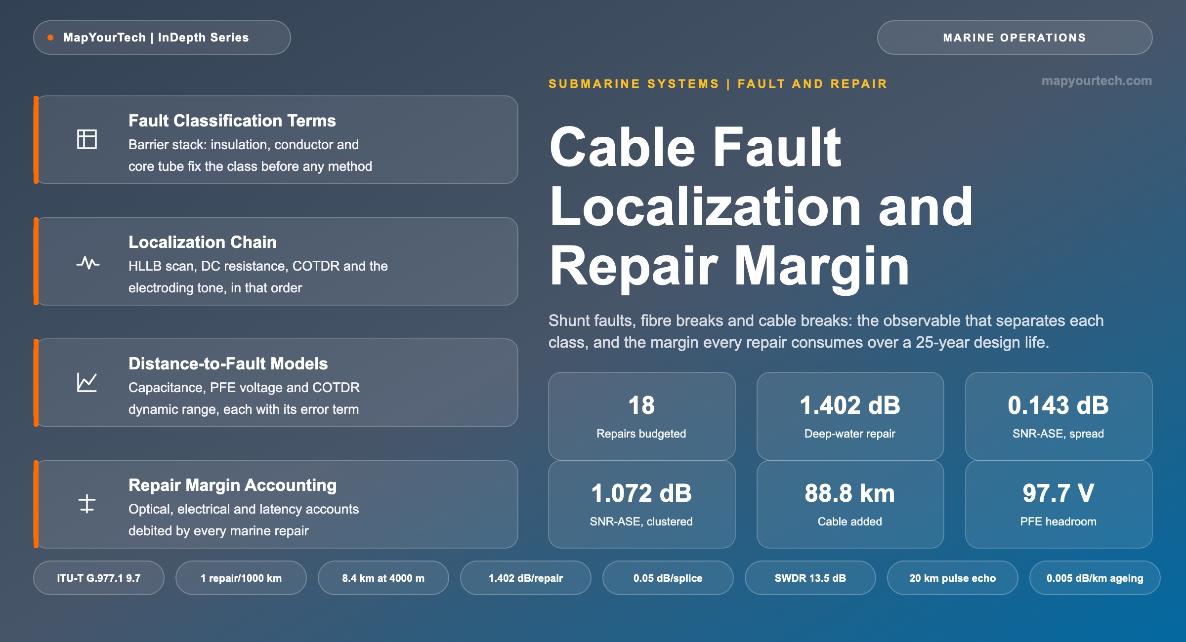
Cable Fault Classification, Localization Methods and Repair Margin Accounting
Shunt faults, open faults, fibre breaks inside intact cable, complete cable breaks and repeater failures — the observable that separates each class, the test sequence that runs from terminal station to cable ship, and the budget margin every repair consumes over a 25-year design life.
Every decibel of margin is paid for once and spent many times.
What You Will Learn
- Separate the four fault classes by the observable each one produces — insulation resistance, cable capacitance, fibre continuity and repeater loop gain — before any localization method is chosen.
- Place a shunt fault from a power feeding equipment (PFE) voltage reading using the DC resistance model, and reproduce the worked case that returns 716 km from a 909 V measurement at 1.10 A.
- Size a coherent optical time domain reflectometry (COTDR) measurement from its single-way dynamic range formula, and reproduce the 13.5 dB result that gives 67.5 km of visible fibre at 0.2 dB/km.
- Quantify the loss one marine repair inserts: 8.4 km of added cable at 4 000 m depth plus two fusion splices, totalling 1.40 dB of excess span loss.
- Convert excess span loss into an amplified spontaneous emission (ASE) penalty across a 125-span chain, and show why 18 repairs cost 0.14 dB spread out and 1.07 dB clustered on one span.
- Anchor a repair allowance against ITU-T G.977.1 clause 9.7 — one deep-water repair per 1 000 km, one shallow-water repair per 15 km with a floor of five.
- Account for the non-optical cost of the same repair set: 88.8 Ω of added conductor resistance, 97.7 V of PFE voltage and 435 μs of added one-way latency.
- Build the terminal-station-to-cable-ship test sequence in the order that preserves evidence, from supervisory alarm through electroding tone to grapnel run.
1. Introduction
A submarine cable system spends its 25-year design life absorbing damage it cannot avoid. The International Cable Protection Committee (ICPC) recorded more than 170 cable repairs worldwide during 2025, close to four repair operations every week across the global plant (measured, ICPC global repair data analysis presented at the ICPC Annual Plenary). Roughly 90% of those events trace to external aggression rather than component failure, and about 80% of the external-aggression population comes from anchors and fishing gear (measured, SubOptic global trends in submarine cable faults). Three quarters of faults occur in water shallower than 100 m, where trawl doors and dropped anchors reach the seabed. None of this is a surprise to the people who design the systems, and none of it is treated as an exception: the damage is priced into the optical power budget before the cable is manufactured, into the power feeding voltage before the terminal equipment is ordered, and into the maintenance contract before the system is commissioned.
The path from an alarm on a network management screen to a cable ship holding position over a damaged section runs through a chain of measurements, and each measurement answers one question only. The supervisory system says which repeater section changed. The power feeding equipment (PFE) says how far along the copper conductor the insulation failed. Coherent optical time domain reflectometry (COTDR) says where inside that section the fibre stopped. An electroding tone, injected as a low-frequency modulation on the feeding current, says where the cable physically lies on the seabed after a trawl has dragged it off its as-laid position. Each of those four answers has a different error term, a different range limit and a different precondition, and choosing the wrong one wastes ship time at a day rate that dominates the cost of the event.
What ties the localization work to the transmission design is margin. Every repair replaces a damaged length with a longer one, because the repair cable has to reach from the seabed to the ship and back down twice. At 4 000 m the added length is measured in kilometres, and kilometres of fibre are decibels of span loss that never come back. Undersea amplifiers run in deep gain saturation, so the amplifier downstream of a lengthened span restores the power level but not the optical signal-to-noise ratio (OSNR), and the amplified spontaneous emission (ASE) contributed by that span rises in exact proportion to the added loss. ITU-T G.977.1 clause 9.7 states the budgeting rule directly: one deep-water repair per 1 000 km of route and one shallow-water repair per 15 km of shallow section, with a floor of five shallow repairs, all over the lifetime of the cable (standard-specified). A designer who does not convert that repair count into decibels has not finished the power budget.
Three separate accounts are debited by the same repair, and they are not interchangeable. The optical account loses span loss and therefore generalized signal-to-noise ratio (GSNR). The electrical account loses power feeding voltage headroom, because the added conductor length adds resistance at roughly 1 Ω/km and the PFE has to raise its output to hold the constant feeding current (typical value, cable technology practice). The latency account loses propagation time, at about 4.9 μs per added kilometre of fibre, which matters on routes sold against a contractual round-trip figure. A 10 000 km system carrying its full ITU-T-budgeted repair set over 25 years accumulates 88.8 km of added cable, and that single number lands in all three accounts at once.
The organising idea of everything that follows is that a fault class is not a description of damage but a statement about which physical barrier in the cable has been breached, and that the breached barrier determines which instrument can see the fault at all. A shunt fault is visible to a DC resistance measurement because the conductor now touches the sea; an open fault is invisible to that same measurement because no current path exists, and it is visible instead to a capacitance measurement. Getting the class wrong at the first step sends the whole test sequence down a path that returns no distance, and the ship sails toward a position derived from an instrument that had nothing to measure. Section 2 fixes the barrier stack and the class definitions before any localization method appears, sections 3 to 8 build the measurement chain from terminal station to ship, and sections 9 to 12 convert the repair population into the margin, voltage and latency it consumes.
The treatment assumes a repeatered system with double-end power feeding, a fibre-pair count in the modern range, and high-loss loopback (HLLB) paths in every repeater. Repeaterless systems appear where their fault behaviour differs, which it does substantially: an unrepeatered link carries its repair allowance as a direct cable-loss term of about 3 dB against a fixed equipment power budget, while a repeatered chain carries it as a fraction of a decibel of ASE penalty spread across more than a hundred spans. The same physical repair costs different things in the two architectures, and the reason is worth understanding before either budget is written.
Takeaway: Fault handling in a submarine system is a budgeting activity as much as a marine one. The barrier breached selects the instrument, the instrument returns a distance with a known error term, and the resulting repair debits the optical, electrical and latency accounts in fixed proportions that the design has to reserve in advance.
2. Cable Fault Definition and Fault-Class Terms
A submarine cable fault is a breach of one or more of the concentric physical barriers that a submarine cable maintains between its functional elements and the sea: the polyethylene insulation that isolates the power conductor, the copper conductor that carries the direct feeding current to the repeaters, the steel strength wires that carry mechanical tension, and the sealed optical core tube that holds the fibres. The class of a fault is defined by which of those barriers has failed, not by what caused the failure.
Read the Full Analysis with Premium
The remaining 89% of this article — the design numbers, trade-offs and field guidance — is part of MapYourTech Premium, along with the full premium library, courses and professional tools.
You May Also Like

-
Free
-
August 22, 2026

-
Premium
-
August 22, 2026

-
Premium
-
August 22, 2026