
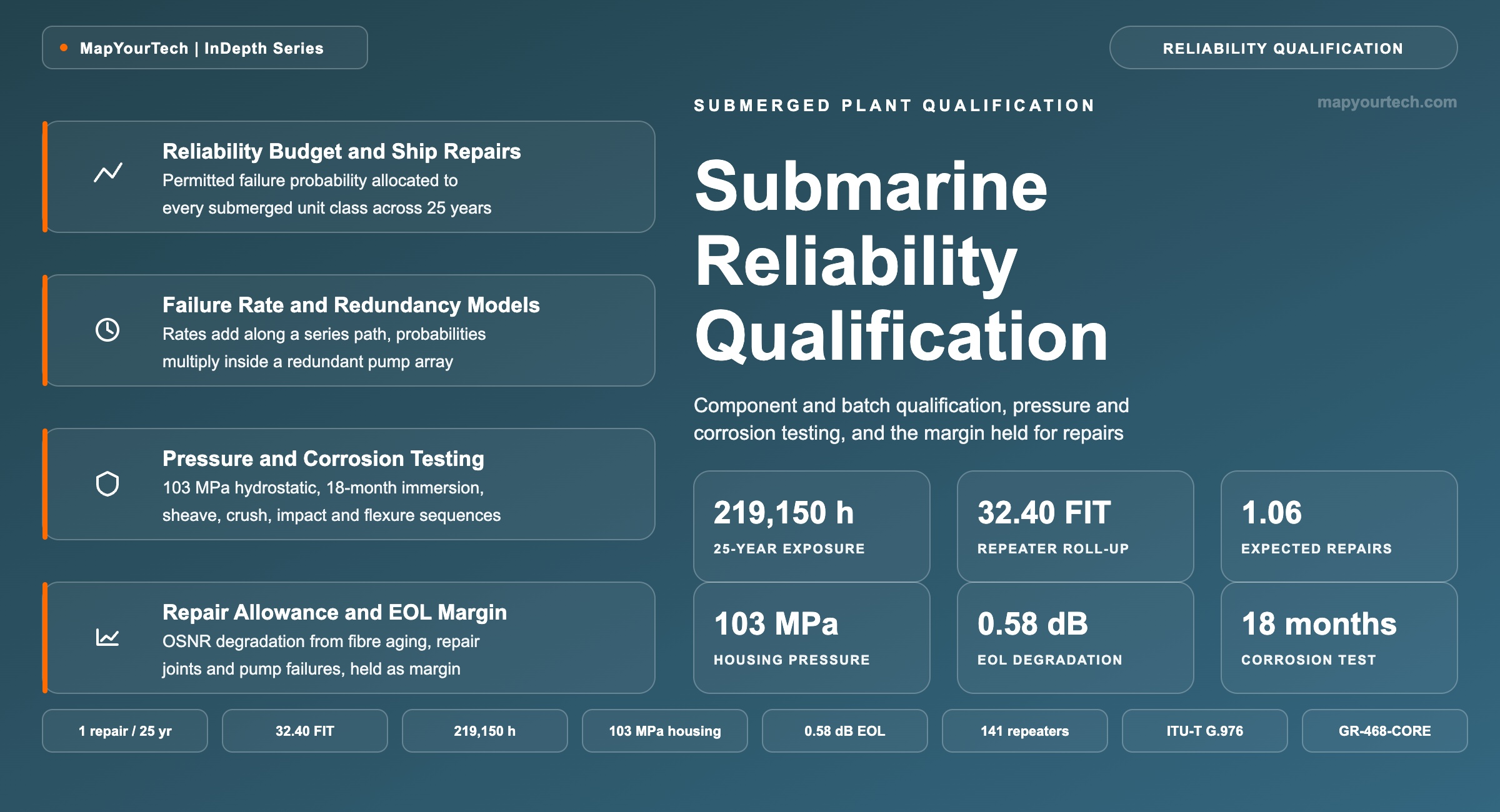
Submarine Reliability Qualification and 25-Year Design Life
Component and batch qualification, pressure and corrosion testing beyond 10,000 m of seawater, the expected ship repair number that bounds submerged-plant failures, and the optical margin held back to absorb every repair the route will need.
A test condition omitted is a specification withdrawn.
What You Will Learn
- Define the expected ship repair number and the reliability budget as Recommendation ITU-T G.972 defines them, and separate both from availability, which excludes ship-repair outages (Section 2, Figure 1).
- Convert a failure-in-time rate into a 25-year probability of failure with P = 1 − exp(−λt) at t = 219,150 h, and reproduce a published 110 FIT pump laser as 2.59 FIT under twofold redundancy (Section 4, Table 2).
- Roll component rates into a 32.4 FIT repeater and locate the 141-repeater point at which that design alone consumes an entire one-repair budget (Section 4, Table 3).
- Allocate a 1.00 expected-repair budget across 150 repeaters, 12,000 km of cable and four branching units, and back out the 15.2 FIT per repeater the allocation requires (Section 5, Table 4).
- Anchor housing pressure qualification at 103 MPa (15,000 psi), equal to 10,240 m of seawater at 1,025 kg/m³, and place it against the 8,000 m depth of the deepest commercial routes (Section 6, Table 5).
- Apply the corrosion condition under study in ITU-T G.976 — aerated sea water at 50 °C for 18 months — alongside the 14-day water-penetration hold and the 30–50 traverse sheave test (Section 6, Figure 5).
- Build an end-of-life allowance from +0.002 dB/km fibre aging, 3 dB per deep repair every 1,000 km and 0.5 dB per shallow repair every 20 km, reaching 0.58 dB of OSNR degradation on a 12,000 km route (Section 7, Table 6).
- Select between full and differential qualification when a design changes, using the repeater dimension, centre-of-gravity and cable-coupling criteria that decide whether a sea trial repeats (Section 8, Figure 7).
1. Introduction
A repeater laid at 6,000 m sits at a seabed temperature near 5 °C under roughly 60 MPa of hydrostatic pressure, and the only maintenance action that reaches it is a cableship recovering the cable to the surface. That constraint fixes where reliability is established. It is established in the factory, before the equipment is loaded, because the seabed offers no second opportunity to establish it. Terrestrial line equipment is specified against a 15-year lifetime with a technician a drive away from the hut; submerged plant is specified against 25 years with a vessel mobilisation, a grapnel run and a mid-ocean joint standing between the fault and its repair. The difference in accessibility, not the difference in physics, is what separates the two qualification programmes, and it is why an undersea amplifier and a terrestrial amplifier built from the same component technologies are held to failure rates that differ by orders of magnitude.
Two numbers carry that difference through a project. The first is the expected ship repair number, the mean count of cableship interventions attributable to system failures over the design life, excluding external aggression. Purchasers typically require that the submerged portion produce no more than one such intervention across 25 years, and a few minutes of outage per year from all other causes. The second is the optical margin held back against those repairs. Every repair inserts a length of spare cable and two new joints into a span, and every insertion costs loss that the amplifier chain must absorb without the traffic falling below its bit error ratio target. The two numbers are coupled: the reliability budget decides how many repairs a system is designed to survive, and the power budget decides whether the system still meets its commissioning specification once they have all happened.
Between those two numbers sits the qualification programme. It runs from raw material selection through component life testing, subassembly stress screening, equipment-level environmental testing, and system-level demonstration on a full-length test bed, and it is audited by an Inspection Authority acting for the purchasers rather than by the supplier alone. Its purpose is to establish, with quantitative confidence and before a single unit is deployed, the failure rate of every part that goes to sea — because those rates are the inputs to the reliability budget, and a reliability budget built on unqualified rates is a statement of hope rather than a design.
This article covers the qualification and reliability machinery for the submerged portion of a repeatered optical fibre submarine cable system: how failure rates are established at component and batch level, how they are combined into a system-level expected ship repair number, how pressure, corrosion and mechanical testing is specified and to what levels, and how the resulting repair count is converted into decibels of held-back optical margin. It does not cover terminal station equipment reliability, route survey and burial engineering, or the commercial structure of maintenance contracts beyond what bears directly on repair count and repair time.
1.1 Origin of the Failure Rate Target
A transoceanic system carries on the order of 150 repeaters, several branching units, a dozen or more gain-equalisation units, and 12,000 km of cable containing thousands of factory joints. Serial reliability applies almost everywhere: any one repeater failure that removes a fibre pair from service is a system failure, so the system failure probability is the sum of the individual probabilities across every unit. Holding a sum of 150 terms below 1.0 requires each term to sit near 0.007, which for a 25-year exposure means a per-repeater failure rate in the low tens of failures per 109 device-hours. Component data published for the terrestrial telecommunications market, gathered on small sample sizes and mostly at assembly level, produces estimates orders of magnitude higher than that. Closing the gap is the work of the qualification programme, and it is closed by three mechanisms operating together: component selection backed by physics-of-failure understanding, redundancy applied where a single component cannot reach the target, and accelerated life testing sized to give statistical confidence at the required failure rate.
The economics reinforce the target. A deep-water repair mobilises a vessel, consumes ship days at a contracted running cost, and removes capacity from service for the duration. Current global repair-time analysis puts the median duration of a submarine cable fault at roughly 40 days from detection to restoration (industry analysis), and even a well-positioned repair under favourable conditions rarely completes in under 14 days. A design that generates two unplanned repairs instead of one over 25 years has therefore doubled a cost measured in millions and doubled an outage measured in weeks. The mechanics of a repair operation — fault localisation, grapnel run, recovery, jointing, re-lay — are the same whether the trigger was a trawler or a failed pump laser, but only the second is inside the supplier's control, and only the second is what the reliability budget bounds.
1.2 The Boundary Between Reliability and Availability
Availability and the expected ship repair number measure different things and are deliberately kept apart. Availability, defined in the ITU-T G.900-series as the ratio of operating time to total time, is calculated for a submarine system with ship-repair outages excluded, because the duration of a marine repair depends on vessel position, weather and port clearance rather than on the equipment design. The expected ship repair number captures exactly what availability leaves out: the count of events that require a vessel. A supplier who improves availability by adding terminal-side protection switching has not changed the expected ship repair number by a single unit, and a supplier who halves the repeater failure rate has not changed the availability figure at all. Design reviews that conflate the two produce contracts in which nobody owns the marine intervention count.
The same separation appears in the fault statistics. External aggression — fishing gear, anchors, abrasion — is excluded from the expected ship repair number because it is a property of the route, not of the equipment, and it is mitigated by burial, armouring and route engineering rather than by component qualification. Industry data compiled by the International Cable Protection Committee puts global cable faults at roughly 150 to 200 per year, with 70–80% caused by accidental human activity (industry statistics). Component failure is a small minority of that total, which is the intended outcome of the qualification programme rather than an accident of it.
Takeaway: Submarine reliability is a pre-deployment quantity. The expected ship repair number bounds equipment-caused marine interventions over 25 years, availability deliberately excludes them, and the qualification programme exists to establish the component failure rates that make the first number calculable at all.
2. Reliability Budget and Expected Ship Repair Number
The reliability budget of a submarine cable system is a model that assigns a permitted failure probability to every class of unit in the submerged portion, chosen so that the sum of expected failures across all units stays below a contracted limit. That limit is the expected ship repair number: the statistical mean count of cableship repairs caused by system component failures over the system design life, with faults from external aggression excluded. Both terms are defined in Recommendation ITU-T G.972 (standard-specified).
Read the Full Analysis with Premium
The remaining 89% of this article — the design numbers, trade-offs and field guidance — is part of MapYourTech Premium, along with the full premium library, courses and professional tools.
You May Also Like

-
Free
-
August 22, 2026

-
Premium
-
August 22, 2026

-
Premium
-
August 22, 2026