
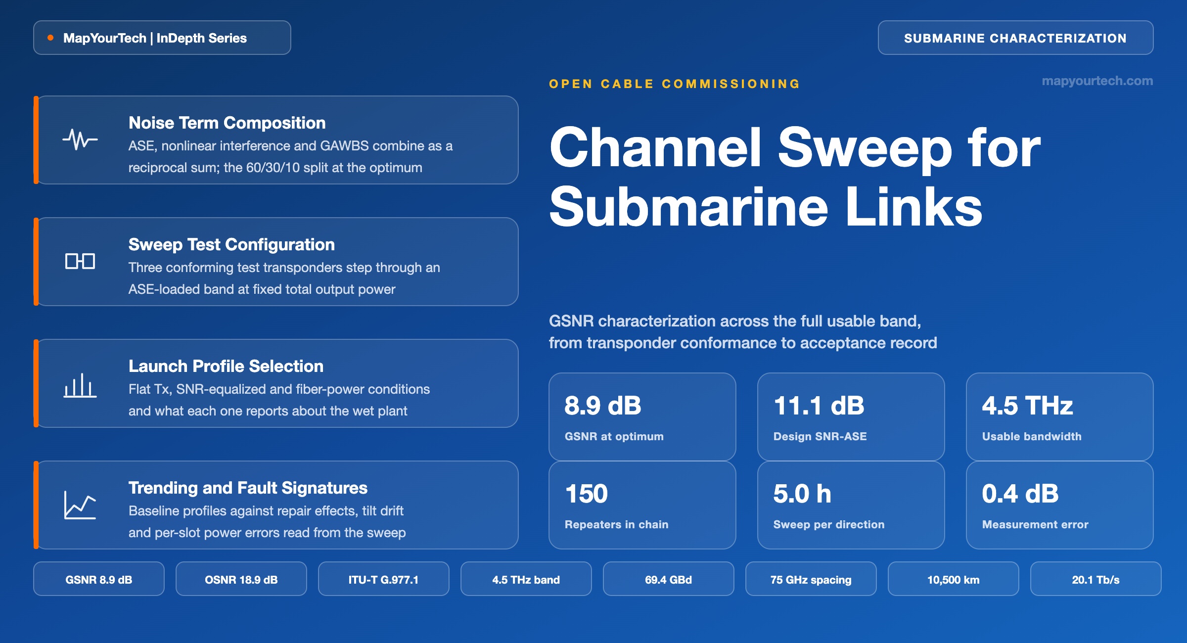
Channel Sweep for Submarine Links: GSNR Characterization
A three-channel test block stepped across the usable band, with amplified spontaneous emission holding every other slot, produces the GSNR-versus-frequency profile that governs open-cable acceptance, spectrum pricing and every later capacity estimate.
Measure the path you will deploy, not the one you modelled.
What You Will Learn
- Define the sweep point as a three-channel modulated block with ASE holding every remaining slot, using the configuration ITU-T G.977.1 specifies (Section 2, Figure 1).
- Convert OSNRASE in 0.1 nm to SNRASE in a 75 GHz channel spacing through the −7.78 dB offset worked in Section 2.
- Partition GSNR into ASE, nonlinear interference and GAWBS noise variances — 60 %, 30 % and 10 % at the nonlinear threshold (Section 3, Figure 2).
- Build the sweep test path from test transponder set, ASE source with WSS shaping, combiner and spectrum-analyzer tap (Section 4, Figure 3).
- Select between Flat Tx, SNR-equalized and fiber-power-equalized launch conditions, and record which one produced the delivered numbers (Section 6, Table 3).
- Quantify sweep duration: 60 points at a 5 min dwell is 5.0 h per direction per fiber pair, and 160 h across a 16-fiber-pair cable run serially (Section 6).
- Anchor pre-emphasis decisions on measured return, where 3.4 dB of transmitter pre-emphasis bought 1.3 dB of delivered SNR in the transatlantic example of Section 6.
- Diagnose sweep anomalies from their signatures: total power steps, hole-burning depressions, saturated Q² and modem calibration drift (Section 9, Table 8).
1. Introduction
An open submarine cable is bought and sold on a quantity that no single instrument reads directly: the generalized signal-to-noise ratio the wet plant delivers, stated as a function of optical frequency across the usable band. ITU-T G.977.1 names GSNR as the measurement parameter for the interoperable cable portion, and the same Recommendation requires that measurements be conducted across the usable bandwidth, because amplifier noise figure, gain shape, scattering and nonlinear interference all vary with frequency (standard-specified, ITU-T G.977.1). Channel sweep is the procedure that produces that function, one center frequency at a time.
The procedure exists because the alternative does not scale. Populating a 4.5 THz band with test transponders on every slot would need sixty coherent modems per fiber pair per direction, which is neither affordable nor available at a cable landing station during commissioning. G.977.1 therefore recommends a minimum of three test transponders plus ASE as power holders for the remainder of the optical spectrum (standard-specified, ITU-T G.977.1). The three-channel block moves; the ASE stays. Each stop yields one Q² reading that maps back to a signal-to-noise value, and the assembled stops form the profile.
Four groups act on that profile directly. Cable purchasers use it to test the delivered plant against the interoperable cable budget agreed at contract, since acceptance turns on measured average and worst-case GSNR rather than on a vendor model. Terminal equipment suppliers use it to predict capacity for a specific modem generation, because GSNR characterizes the line alone and is therefore transferable between transponder vendors. Spectrum sellers use it to price sub-bands, since a fiber pair partitioned by frequency is worth different amounts at different frequencies. Operations teams use the commissioning sweep as the baseline against which aging, repairs and gain-tilt changes are later measured, which is why the measurement conditions matter as much as the values.
The sections that follow build the procedure from its primitive. Section 2 defines what one sweep point contains and separates the four signal-to-noise quantities that are routinely conflated. Section 3 gives the noise partition and the inverse back-to-back mapping that turns a bit error ratio into a line-only metric. Sections 4 and 5 cover the physical test path and the bandwidth arithmetic. Sections 6 and 7 cover sweep planning, launch profile selection and execution. Sections 8 through 12 cover lifetime trending, fault signatures, method alternatives, roadmap and a consolidated reference set. Throughout, the boundary conditions are stated with the values: this treatment applies to dispersion-uncompensated repeatered systems where the Gaussian noise model holds, and Section 9 names where it does not.
2. Channel Sweep Definition and Component Terms
A channel sweep is a commissioning measurement in which a small block of modulated test channels is stepped in frequency across a submarine cable's usable band, with amplified spontaneous emission holding every unused slot at operational power, so that signal-to-noise performance is sampled at each center frequency in turn. The output is a table of values against frequency, not a single number.
2.1 Distinctions From Adjacent Quantities
Five quantities carry signal-to-noise names in an open-cable report, and confusing any two of them changes the answer by several decibels. Each is separated below by exactly what it includes.
- OSNRASE against SNRASE — the same linear amplifier noise, expressed in different bandwidths. OSNRASE is referenced to 0.1 nm (12.5 GHz at 1550 nm); SNRASE is referenced to the channel spacing, which removes the dependence on how many channels happen to be lit.
- SNRASE against GSNR — SNRASE counts only amplified spontaneous emission. GSNR adds nonlinear interference and guided acoustic wave Brillouin scattering, so GSNR is always the lower of the two on a lit cable.
- GSNR against SNREXT — SNREXT is what the inverse mapping returns directly, and it still contains SNRi, the residual interaction between modem and line: polarization-dependent loss, wavelength tolerance, equalization-enhanced phase noise and imperfect dispersion compensation. Removing SNRi in reciprocals leaves GSNR.
- GSNR against SNRTOT — SNRTOT adds the modem's own back-to-back noise, SNRMODEM. GSNR describes the line and transfers between transponder vendors; SNRTOT describes one link with one modem in it and does not transfer.
- Channel sweep against power hunt — a sweep steps the test block in frequency at a fixed launch profile and returns performance against frequency. A power hunt holds frequency and steps launch power, returning performance against power. The two answer different questions and are run in sequence, not interchangeably.
Read the Full Analysis with Premium
The remaining 87% of this article — the design numbers, trade-offs and field guidance — is part of MapYourTech Premium, along with the full premium library, courses and professional tools.
You May Also Like

-
Premium
-
August 22, 2026

-
Premium
-
August 22, 2026
-
Premium
-
August 22, 2026