
C+L Band Submarine Line Design and SRS-Induced Tilt Control
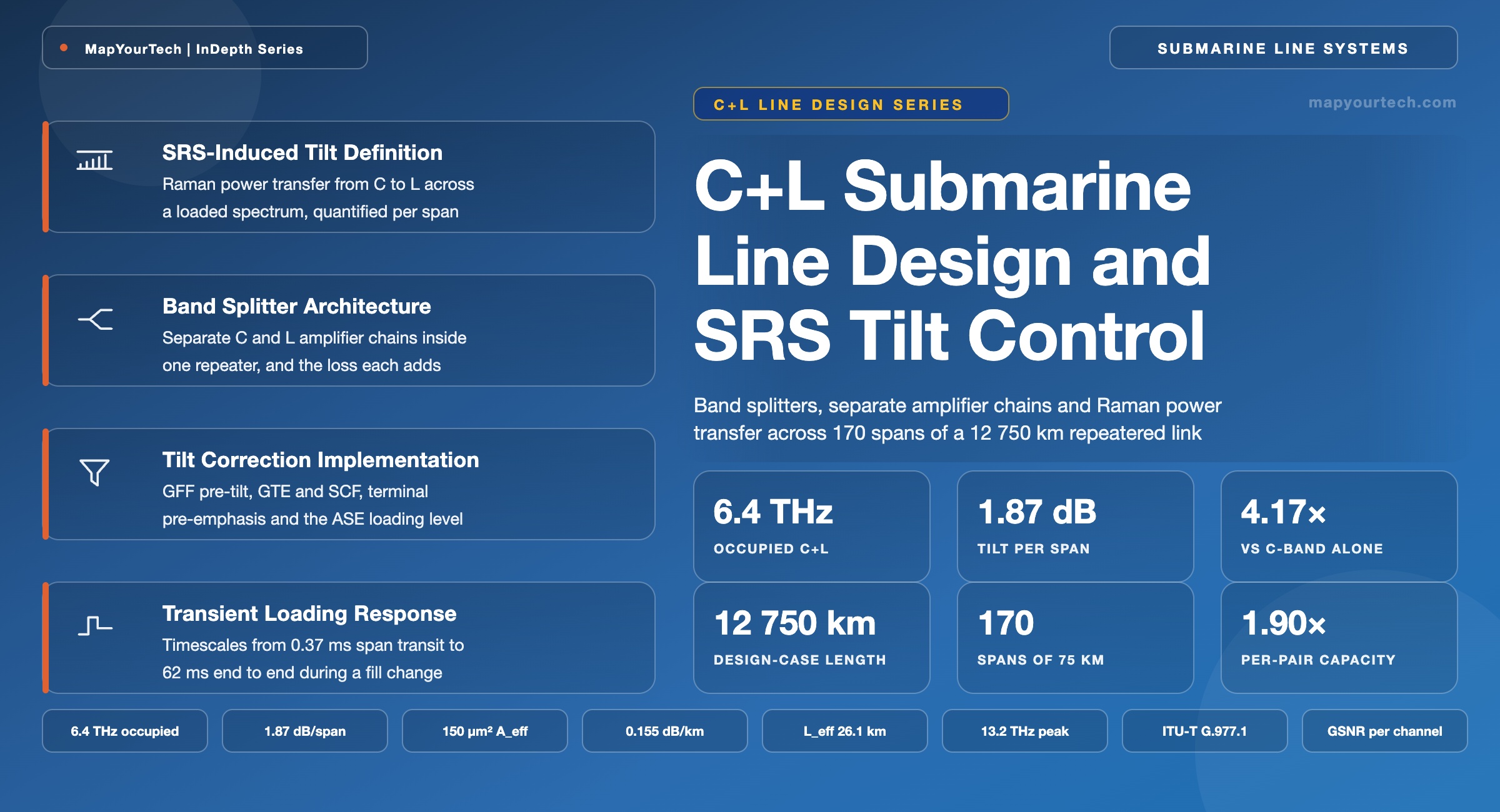
Band splitters and separate amplifier chains, Raman power transfer from the C-band into the L-band, the correction layers that hold the spectrum flat in steady state, and the transient behaviour that appears when channel loading changes.
A wider band adds capacity and inherits every impairment across it.
What You Will Learn
- Define SRS-induced tilt from the coupled power equations and separate it from occupied bandwidth, spanned bandwidth and channel spacing, using the 6.4 THz occupied and 7.5 THz spanned figures of Section 2.
- Compute the per-span tilt of a C+L submarine line and reproduce the 1.87 dB design-case value at 21.5 dBm launch, 150 um² effective area and 26.1 km effective length.
- Place the band splitter, the two amplifier chains, the gain flattening filters and the shared pump unit inside a repeater amp-pair, following Figure 2.
- Quantify the four budget penalties of a split-band repeater: 0.5 dB C-band OSNR, 1.0 dB L-band OSNR, 0.5 dB per-band output power, and a four-fold increase in per-span tilt.
- Separate the four tilt correction layers by the timescale on which each is set, from the fixed pre-tilt in the gain flattening filter to the continuously adjusted ASE loading level.
- Trace a channel loading change through the three timescales that govern it: 0.37 ms of span transit, microseconds of amplifier gain recovery, and 62 ms of end-to-end propagation on a 12 750 km link.
- Anchor a C+L line against the ITU-T G.977.1 open-cable parameter set: passband, gain deviation, slope of tilt, repeater total output power and noise figure.
- Select between C+L operation and added fibre pairs using the ordered condition ladder of Figure 5 and the capacity ledger of Section 9.
1. Introduction
A transoceanic fibre pair carrying only the C-band leaves roughly half of the erbium-accessible low-loss window unlit. Extending that pair into the L-band doubles the spectrum it can sell, and a submarine system that does so carries two amplifier chains inside every repeater, a band splitter and a band combiner at each amplification site, and a spectral-management scheme that has to hold thousands of kilometres of accumulated Raman power transfer inside a fraction of a decibel. Exactly one commercial submarine cable has been built that way. The Pacific Light Cable Network, supplied by SubCom, carries six fibre pairs at 24 Tb/s per pair for 144 Tb/s of system capacity over roughly 13 000 km of the Pacific, and it remains the only submarine cable deployed with C+L band amplification (vendor and trade-press record). Every large-capacity cable built since has taken the other path, adding fibre pairs in the C-band only.
The reason is arithmetic rather than fashion. Adding the L-band to a repeatered submarine line costs 0.5 dB of C-band optical signal-to-noise ratio (OSNR) and 1.0 dB of L-band OSNR against an otherwise identical C-band design, splits the repeater total output power between two gain blocks so each band gives up a further 0.5 dB, and increases the per-span stimulated Raman scattering (SRS) tilt by roughly a factor of four rather than a factor of two, because the tilt scales with the product of total launched power and spanned bandwidth and both roughly double (published submarine-system analysis). None of those penalties is fatal on its own. Together they mean the second band returns noticeably less than a second band's worth of capacity, and the electrical power needed to run twice as many amplifiers has to come from the same power feed equipment (PFE) voltage and the same line current.
Where C+L does earn its place is on the capacity available inside a single fibre pair. Cable slots, repeater housings, ship time and marine route permits are all counted in fibre pairs; spectrum is not. A design that can put 45 to 50 Tb/s through one pair instead of 24 to 25 Tb/s changes the ratio between wet-plant cost and delivered capacity even when it leaves total cable capacity unchanged, and that ratio is what decides upgrades on cables already in the water. The physics that makes the second band possible is the same physics that makes it difficult, because the erbium ion needs a different average population inversion to give useful gain at 1590 nm than it needs at 1545 nm, and because a comb 7.5 THz wide sits close enough to the silica Raman gain peak at 13.2 THz for its own short-wavelength half to act as a pump for its long-wavelength half.
Tilt correction in a submarine C+L line is a layered problem with layers set on four different timescales. A fixed pre-tilt is etched into the gain flattening filter (GFF) of every amplifier at manufacture and cannot be changed once the repeater is potted. Gain tilt equalizers (GTE) and shape compensation filters (SCF) are inserted into the cable every fifteen to twenty spans during manufacture and cable lay, and they too are passive. Terminal pre-emphasis is set at commissioning from a measured receive spectrum and reset after every repair. Amplified spontaneous emission (ASE) loading is adjusted continuously so the line always sees the same total power whether or not the traffic channels are present. Each layer removes a residual the layer above it cannot reach, and the whole stack exists because an uncorrected 1.87 dB per span accumulates across 170 spans into a number no receiver could work with.
Transients are where the two bands stop behaving as separate systems. Adding or removing channels in the C-band changes the total power that pumps the L-band, so an L-band channel that was never touched sees its received power move. The redistribution itself is not slow: Raman scattering responds on the femtosecond scale of the molecular vibration and the power profile therefore reorganises within a single span transit, 0.37 ms over 75 km of silica. What is slow, relative to that, is everything built to respond to it. Erbium-doped amplifiers recover gain on a timescale set by the metastable lifetime near 10 ms, shortened to tens or hundreds of microseconds by the deep saturation a submarine amplifier runs in, and the chain settles serially at the propagation velocity of the link, so a 12 750 km system takes 62 ms for the far end to learn about a change at the near end.
This article covers the wet-plant and terminal design of a repeatered C+L submarine line at the level a system engineer needs to specify or evaluate one: the definition and arithmetic of SRS-induced tilt, the split-band repeater architecture, the models that predict tilt and generalized signal-to-noise ratio (GSNR), the four correction layers and what each removes, transient behaviour during loading changes, benchmarking against a C-band space division multiplexing (SDM) design, and the open-cable parameters that make a C+L line specifiable to a third-party terminal vendor. Unrepeatered and festoon links are outside its scope, because their single-span geometry removes the cascade problem that defines the repeatered case; readers working that side of the boundary will find the mechanism treated separately in the MapYourTech material on unrepeatered submarine transmission systems. Multiband operation beyond C+L is also outside scope: the amplifier efficiency and fibre attenuation available in the S-band and beyond do not currently support a transoceanic power budget.
The design case used throughout is a 12 750 km trunk of 170 spans at 75 km, on pure silica core fibre with 150 um² effective area and 0.155 dB/km attenuation, loading 3.2 THz in each band for 6.4 THz occupied and 7.5 THz spanned, at a combined launch of 21.5 dBm into the fibre after splitter loss. Those inputs are stated as a design case rather than as a measurement of any deployed system, and every number derived from them is labelled as derived. Where a figure comes from a standard, a published measurement or a vendor statement, the sentence carrying it says so.
Takeaway: C+L in submarine systems is a spectrum decision constrained by a power budget. The second band roughly doubles per-fibre-pair capacity, costs 0.5 to 1.0 dB of OSNR and quadruples per-span SRS tilt, and needs an amplifier count and pump power the cable powering has to support.
2. SRS-Induced Tilt Definition and Component Terms
SRS-induced tilt is the difference in received power between the highest-frequency and lowest-frequency channels of a wideband multiplex after one fibre span, caused by stimulated Raman scattering transferring power from shorter wavelengths to longer wavelengths. SRS-induced tilt is measured in decibels and quoted per span or per link.
The mechanism is inelastic scattering of light by the molecular vibrations of the silica glass. A photon at a higher optical frequency scatters into a photon at a lower frequency, with the frequency difference taken up by an optical phonon. In a wavelength-division-multiplexed (WDM) comb every channel is simultaneously a potential pump for every channel below it in frequency and a potential Stokes wave for every channel above it, so the process runs without being invoked. The higher-frequency channel acts as a pump and is depleted; the lower-frequency channel receives Raman gain. Between signal channels of one comb the process is named inter-channel stimulated Raman scattering (ISRS), and its spectral consequence is an approximately linear power slope across the occupied spectrum, rising toward longer wavelengths. In submarine C+L systems the same effect is often called self-induced SRS or, more loosely, Raman tilt.
Read the Full Analysis with Premium
The remaining 89% of this article — the design numbers, trade-offs and field guidance — is part of MapYourTech Premium, along with the full premium library, courses and professional tools.
You May Also Like

-
Premium
-
August 22, 2026

-
Premium
-
August 22, 2026
-
Premium
-
August 22, 2026