
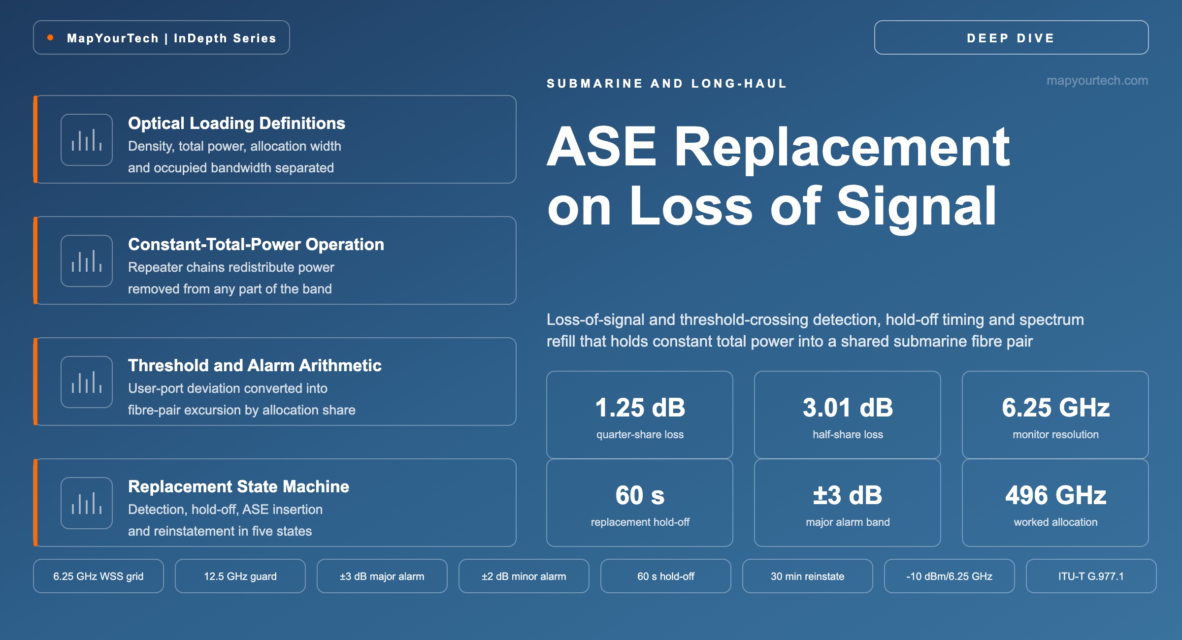
Spectrum Controller ASE Replacement on Loss of Signal
Loss of signal and threshold-crossing detection trigger ASE replacement so the remaining users keep a filled spectrum and constant total power into the fibre pair.
Power concentrated into fewer channels is power spent on distortion.
What You Will Learn
- Define optical loading, power spectral density, allocation width and occupied bandwidth as four separate quantities, using the anatomy of Figure 1.
- Convert a contracted density of -10.0 dBm per 6.25 GHz into the 9.0 dBm terminal target and the 496 GHz allocation it implies.
- Quantify the launch-power displacement a loading loss imposes, from 0.46 dB at a tenth of the passband to 3.01 dB at a half.
- Place the twin wavelength selective switches, the total-power tap, the optical channel monitor and the ASE source in the signal path of Figure 4.
- Convert a plus or minus 3 dB user threshold into the 0.41 to 1.75 dB fibre-pair excursion it admits across allocation shares.
- Sequence a fault through the five controller states, from threshold crossing to the 60 s hold-off, replacement and reinstatement.
- Select hold-off values against each tenant's backhaul recovery profile rather than applying one cable-wide interval.
- Anchor the design to ITU-T G.977.1 optical loading and the SubOptic Spectrum Sharing Working Group parameter set.
1. Introduction
A submarine repeater holds its total output power constant. Every amplifier in the chain runs deep in gain saturation, with the pump current fixed by a constant-current driver and no per-channel control of any sort, because a device sitting under four kilometres of water for twenty-five years cannot carry a feedback loop that might drift or a component that might need adjustment. That design choice is what makes the wet plant reliable, and it is also what makes an unloaded fibre pair dangerous. When optical power disappears from part of the spectrum, the repeater does not reduce its output to match. It redistributes the same total power across whatever remains, and every surviving channel arrives at the far end with more power than its design case assumed.
On a single-owner fibre pair that behaviour is managed by one terminal vendor who controls every carrier. Spectrum sharing removes that control. The fibre pair is partitioned into contiguous blocks and each block is operated by a different party, with its own submarine line terminal equipment (SLTE), its own channel plan, its own maintenance windows and its own failure modes. A transponder shelf that loses power in one operator's building changes the launch conditions for every other operator on the cable. The Spectrum Management Block (SMB), described by the SubOptic Spectrum Sharing Working Group, exists to break that coupling, and the function that does the breaking is amplified spontaneous emission (ASE) replacement on loss of signal.
The mechanism is short to state and long to engineer. An optical channel monitor and a total-power tap watch each user's input port. When the measured power leaves its contracted envelope, or vanishes entirely, the controller raises an alarm and starts a hold-off timer. If the condition persists to expiry, the controller carves shaped noise from an unseeded amplifier pair into the whole of that user's frequency range, at the power spectral density the contract specifies, and the fibre pair returns to the loading its repeaters were commissioned against. The remaining users see nothing. When the user restores its terminal, a second hold-off runs before the allocation is handed back, so a terminal that is flapping does not modulate the launch conditions of the entire cable.
Three properties of modern cable design make this workable. Dispersion-unmanaged designs, usually written D+, accumulate large chromatic dispersion and operate close to the linear region, so a coherent carrier and a block of shaped noise at the same spectral density present nearly the same perturbation to their neighbours and can be exchanged for one another. Wavelength selective switches with 6.25 GHz pixel granularity make the exchange addressable at a useful resolution. And the constant-total-power repeater, the same property that creates the problem, guarantees that restoring the total also restores the per-channel powers without any per-channel action.
What the mechanism cannot do is hide the arithmetic. A user holding a quarter of the passband that goes dark removes 25% of the launched power, which raises every surviving channel by 1.25 dB once the chain re-saturates. Doubling that fraction raises them by 3.01 dB. Those numbers are not penalties in themselves; they are displacements from the launch power the cable was optimised at, and on a link already sitting near its nonlinear optimum a positive displacement costs generalised signal-to-noise ratio in both directions at once. The hold-off timer that gives a user sixty seconds to fix its own problem is sixty seconds during which the rest of the cable runs off-design.
This article works the mechanism through end to end: what the quantities are, why the constant-power repeater behaves the way it does, how the SMB is built, what the threshold arithmetic gives, how the state machine sequences detection through reinstatement, and where the approach stops working. The boundary conditions are stated where they apply — dispersion-managed cables, fast transients, terrestrial extensions and the monitoring resolution limit each place a real constraint on what replacement can achieve. Readers approaching the commercial and demarcation side of the same problem will find it treated separately in the MapYourTech article on spectrum-as-a-service engineering, and the wider context of partitioned cables in the treatment of open submarine cable systems.
Takeaway: The repeater chain holds total output power constant, so power removed from one part of the spectrum reappears in the rest. ASE replacement puts the power back in the frequency range where it was lost, which is the only place that restores both the total and the per-channel distribution.
2. Optical Loading, Power Spectral Density and ASE Replacement Definitions
Optical loading is the practice of holding every hertz of a cable's usable passband at a specified power spectral density, whether or not that hertz carries traffic. Loading occupies unused spectrum with shaped amplified spontaneous emission or unmodulated carriers so the repeater chain always sees the total input power and spectral distribution it was commissioned against. ASE replacement is loading applied reactively: shaped noise substituted for a user allocation that has stopped meeting its contracted power.
Read the Full Analysis with Premium
The remaining 89% of this article — the design numbers, trade-offs and field guidance — is part of MapYourTech Premium, along with the full premium library, courses and professional tools.
You May Also Like

-
Free
-
August 22, 2026

-
Premium
-
August 22, 2026

-
Premium
-
August 22, 2026