
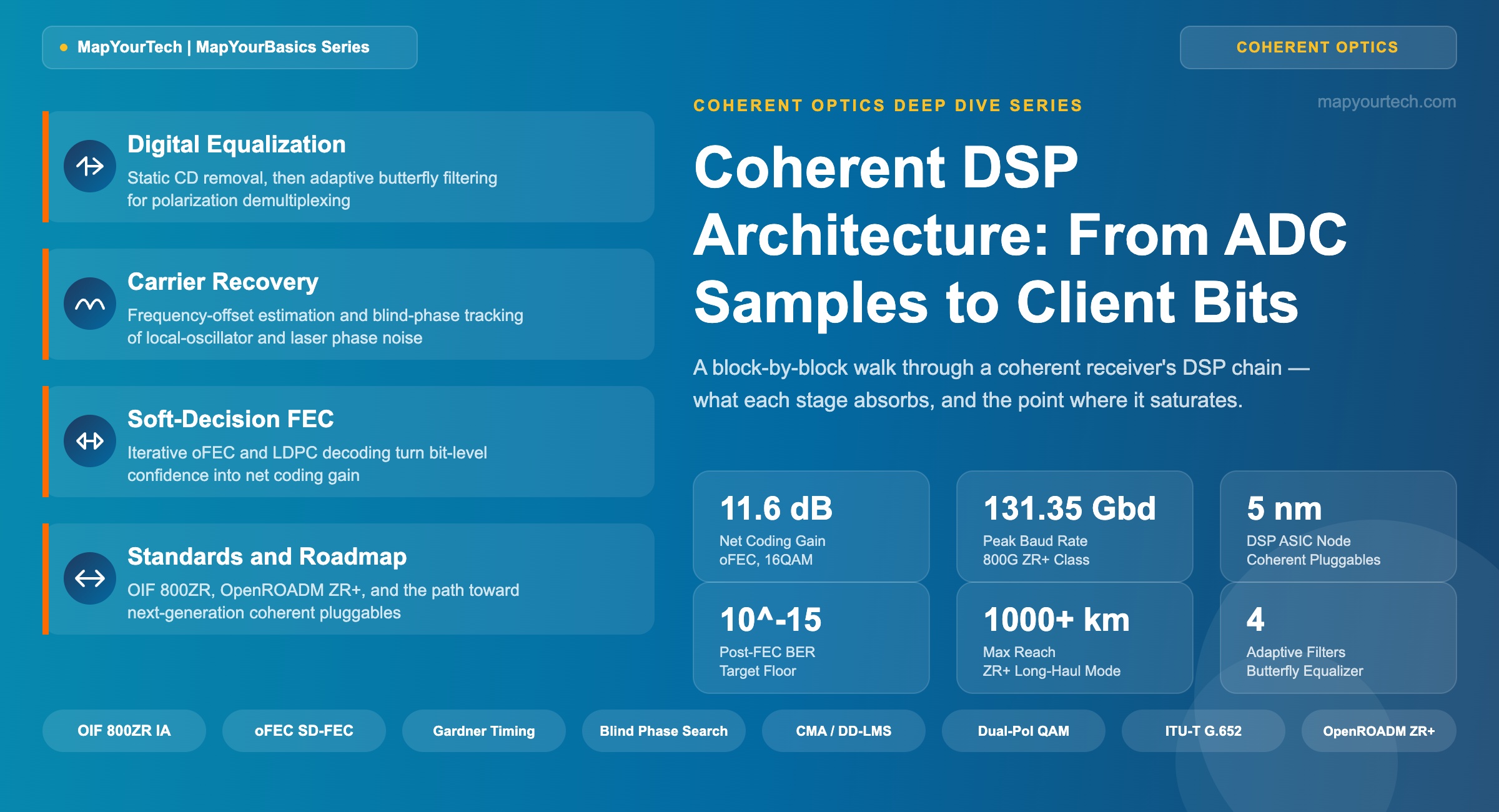
Coherent DSP Architecture: From ADC Samples to Client Bits
A block-by-block walkthrough of a modern coherent receiver's digital signal processing chain, tracing what each stage absorbs, in what order, and where it runs out of headroom.
1. Introduction
A coherent receiver front end delivers four streams of raw voltage samples — in-phase and quadrature for each polarization — running at roughly twice the symbol rate. None of those samples represent a usable bit yet. Between that raw waveform and a client-side Ethernet frame sits a digital signal processing chain that removes chromatic dispersion, undoes an arbitrary and drifting state of polarization, tracks a local oscillator that is never quite at the right frequency or phase, and finally hands soft decisions to a forward error correction decoder that pulls the last several decibels of margin out of noise that would otherwise make the link unusable.
Every one of those steps is a bounded operation. Each block in the chain is built to absorb one category of impairment, and each one saturates — stops improving, or starts making things worse — once that impairment exceeds a specific threshold. Vendors advertise capacity and reach; the DSP chain is where that capacity and reach are actually paid for, block by block, in silicon area, power, and latency.
This article walks the chain in the order signals actually pass through it: analog-to-digital conversion, static and dynamic equalization, timing and carrier recovery, symbol demapping, and soft-decision FEC decoding. For each block, three questions are answered — what impairment does it target, what does the correction look like mathematically, and where does it stop working. The goal is a reference an engineer can return to when a link's pre-FEC BER creeps toward the FEC limit and the question becomes which block in the chain is actually the bottleneck.
The scope is the receive-side DSP of a dual-polarization coherent transceiver operating at typical DWDM line rates from 100G through 800G, applicable equally to long-haul line systems and to pluggable coherent modules built to the OIF 400ZR and 800ZR implementation agreements. Transmit-side DSP — pulse shaping, pre-emphasis, digital pre-distortion — is referenced only where it changes what the receiver must undo.
2. Foundational Concepts
Why coherent detection needs a DSP chain at all
Direct-detection receivers recover only optical power — the photodiode's square-law response destroys phase information on contact. A coherent receiver mixes the incoming signal with a free-running local oscillator (LO) laser in a 90-degree optical hybrid, then samples the resulting in-phase and quadrature beat terms on balanced photodiodes. This preserves amplitude, phase, frequency, and — when the front end splits the signal by polarization first — the full polarization state. That completeness is the entire point of going coherent, and it is also why the receiver needs heavy DSP: every one of those recovered dimensions comes tangled with a fiber or component impairment that has to be untangled digitally before a bit decision means anything.
Dual-polarization quadrature amplitude modulation (DP-QAM) doubles capacity by transmitting two independent data streams on orthogonal polarizations, recovered afterward with a polarization-diversity front end and a coherent mixer per polarization. This produces four analog signals — XI, XQ, YI, YQ — each digitized by its own ADC.
The impairments the chain exists to remove
Four impairment classes dominate a coherent link, and the DSP chain is organized almost exactly around them:
- Chromatic dispersion (CD) — group velocity differences across the signal's spectrum spread pulses in time. It accumulates linearly with fiber length and changes slowly (thermally), so it is corrected with a static filter.
- Polarization effects — polarization-mode dispersion (PMD) and random rotation of the state of polarization along the fiber mix the two polarization tributaries together. These change on millisecond timescales, so they need an adaptive filter.
- Carrier frequency and phase offset — the LO laser is never frequency-locked to the transmit laser, and both have finite linewidth, so a residual frequency offset and a randomly walking phase corrupt every symbol until removed.
- Additive noise and residual distortion — amplified spontaneous emission (ASE) from optical amplifiers, laser phase noise, and fiber nonlinearity set a noise floor no equalizer can remove; this is what FEC exists to work around.
Read the Full Analysis with Premium
The remaining 89% of this article — the design numbers, trade-offs and field guidance — is part of MapYourTech Premium, along with the full premium library, courses and professional tools.
You May Also Like

-
Free
-
September 4, 2026

-
Premium
-
September 4, 2026

-
Premium
-
September 4, 2026