
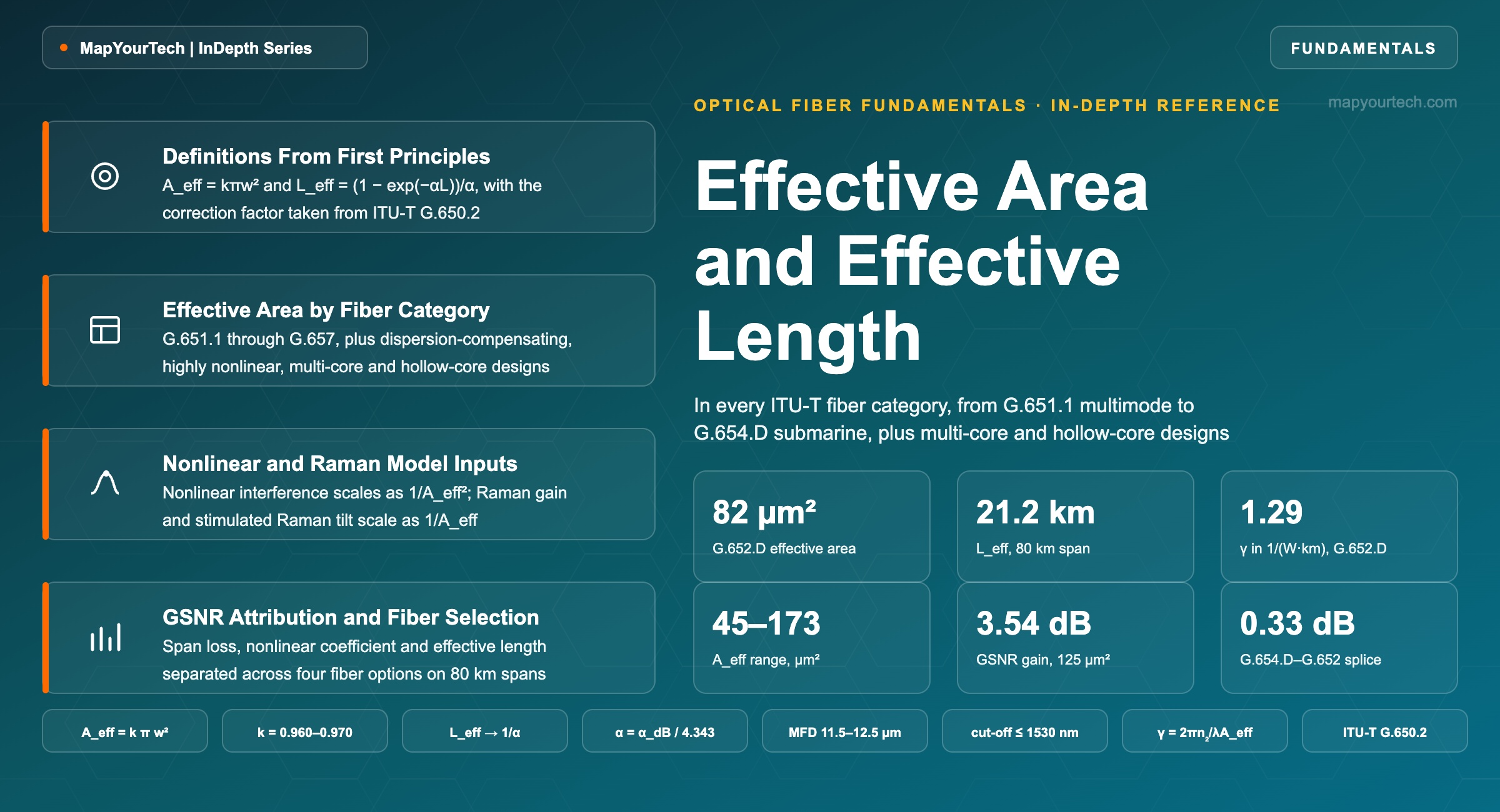
Effective Area and Effective Length in Optical Fiber
The two geometric quantities that set how much nonlinear interference a span generates, derived from first principles and tabulated across every fiber category from multimode to hollow core.
Effective area is the denominator every nonlinear effect in the fiber shares.
What You Will Learn
- Define effective area from the ITU-T G.650.2 Appendix II integral and convert a 10.4 µm mode field diameter into the 82 µm² effective area of G.652.D fiber (Section 2, Figure 1).
- Compute effective length from (1 − e−αL)/α and read the 21.2 km that an 80 km span at 0.20 dB/km delivers against its 21.7 km asymptote (Section 5, Figure 2).
- Read effective area across every ITU-T category from G.651.1 multimode to G.657 bend-insensitive, and locate the 45–54 µm² of G.653 against the 102–173 µm² of G.654.D (Section 6, Table 5).
- Convert effective area into the nonlinear coefficient γ = 2πn2/(λAeff) and separate the 1.29 W−1km−1 of G.652.D from the 0.68 W−1km−1 of a 125 µm² pure-silica-core fiber (Section 4).
- Attribute a 3.5 dB GSNR gain to its three sources — span loss, nonlinear coefficient and effective length — for an 82 µm² to 125 µm² fiber change on 80 km spans (Section 9, Table 10).
- Predict splice loss from mode field mismatch and reproduce the 0.296 dB measured on a G.654.D-to-G.652 joint and the 0.162 dB a bridge fiber returns (Section 10, Figure 4).
- Quantify the Raman cost of a large effective area: 13.1 dB of on-off gain on 82 µm² fiber falls to 8.6 dB on 125 µm² at the same 0.5 W pump (Section 7, Chart 4).
- Score a fiber choice against six weighted criteria and return one category per route archetype using the worksheet of Section 12 (Table 14).
1. Introduction
ITU-T G.652, G.653, G.654, G.655, G.656 and G.657 each recommend a nominal mode field diameter and a tolerance on it, and none of them recommends a value for effective area. Effective area is defined, and its test methods are given, in ITU-T G.650.2 Appendix II and Appendix III. It appears as a parameter that shall be stated, per fiber type, in ITU-T G.977.1 clause 9.6.1 for submarine cable systems. The quantity that decides how much nonlinear interference a span generates is therefore a measured product attribute and a procurement term, not a recommended fiber value, and a planner who reads only the Recommendation tables will not find it.
That gap has a practical consequence. A route engineer who needs the nonlinear coefficient of the installed plant has three options: take the effective area from the fiber manufacturer's product information sheet, derive it from the specified mode field diameter through the Gaussian relation of G.650.2 Equation II-3 with its correction factor, or measure it by near-field scan. The three routes do not agree to better than a few per cent, and on large-effective-area designs they can differ by six per cent, which is 0.5 dB in the nonlinear interference term.
Two Quantities, One Product
Effective length is the second half of the pair. Loss removes power as the signal propagates, so the Kerr effect is not distributed evenly along a span: it is concentrated in the first few kilometres where the power is highest. Effective length collapses that decaying interaction into the length of lossless fiber that would produce the same nonlinear phase, and for an 80 km span of fiber at 0.20 dB/km it evaluates to 21.2 km. Lengthen the span to 120 km and effective length rises only to 21.6 km, because the tail of the span contributes almost nothing. The nonlinear phase a span accumulates is γPLeff, so effective area and effective length enter it as a ratio and a length, and neither one alone predicts the result.
Both quantities move together when a fiber is changed. A pure-silica-core fiber with a 125 µm² effective area lowers the nonlinear coefficient by 2.8 dB against standard single-mode fiber, and its lower attenuation raises effective length by 24%, which returns 1.9 dB of that gain to the nonlinear interference term. The net movement is smaller than either number alone suggests, and Section 9 attributes it line by line.
Scope of This Reference
This article covers effective area and effective length as design quantities for coherent optical transmission: their definitions, their standardised measurement, their values across every fiber category in the ITU-T G.65x series plus specialty, multi-core and hollow-core designs, and the four mechanisms they feed — Kerr nonlinear interference, stimulated Raman scattering, Raman amplification and splice loss. It does not cover fiber manufacturing processes, refractive index profile synthesis, or the mechanical and environmental attributes of cable.
Every category in the fiber Recommendations is tabulated with its specified mode field diameter and the effective area that follows from it. Where a manufacturer publishes an effective area, that figure is given with its evidence class beside the derived one, so the reader can see the size of the gap between the two routes. The comparison is applied to four route archetypes in Section 12, and the worksheet there returns one fiber category per archetype rather than a single recommendation.
Takeaway: Effective area is a measured product attribute that no fiber Recommendation puts a number on, while effective length is a derived quantity that saturates at 1/α and stops rewarding longer spans. Both enter the nonlinear phase as the product γPLeff, so a fiber change that improves one and worsens the other has to be evaluated as a whole.
2. Effective Area and Effective Length Definitions
Effective area is the cross-sectional area over which the guided optical power would have to be spread, at uniform intensity, to produce the same nonlinear interaction as the real mode field. It is measured in square micrometres and it is a property of the mode, not of the core: for a standard single-mode fiber whose core is 8.2 µm across, the effective area is about 82 µm², roughly 55% larger than the geometric core area, because the mode field extends into the cladding.
Effective length is the length of hypothetical lossless fiber that would produce the same nonlinear phase accumulation as a real span of length L with attenuation coefficient α. It is measured in kilometres, it is always shorter than the span, and it approaches the fixed limit 1/α as the span grows.
2.1 Distinctions From the Adjacent Quantities
Four quantities sit next to effective area and get substituted for it. Separating them is where most of the teaching in this section happens, because the confusion an engineer meets in practice is almost always a confusion between two neighbours rather than ignorance of one.
Core area is the geometric area of the doped region, π times the square of the core radius. For a G.652.D fiber with an 8.2 µm core it is 53 µm². The guided mode is wider than the core, so core area understates effective area by about a third and is never the right term in a nonlinear calculation.
Mode field diameter is the diameter at which the field amplitude of the fundamental mode falls to 1/e of its peak, equivalently the diameter at which intensity falls to 1/e². It is the quantity the fiber Recommendations specify, it is what a splice loss calculation needs, and it is related to effective area through the Gaussian form Aeff = kπw² with MFD = 2w. It is not itself an area.
Mode field area is πw² without the correction factor. For the same fiber it is 84.9 µm² against an effective area of 82 µm². The 3.5% gap is the error the Gaussian shape assumption carries, and ITU-T G.650.2 states explicitly that the Gaussian approximation is accurate for G.652 and G.654 step-index fibers near the LP11 cut-off but not at much longer wavelengths, and not for G.653 dispersion-shifted fiber at all.
Effective length is a length, not an area, and it belongs to the span rather than to the fiber. Two spans of the same fiber with different lengths have different effective lengths; two fibers with the same length and different attenuation also have different effective lengths. Effective area travels with the fiber; effective length is recomputed for every span.
| Quantity | Symbol | Value | Unit | What it governs |
|---|---|---|---|---|
| Core area | πa² | 53 | µm² | Nothing directly; a fabrication dimension |
| Mode field diameter | 2w | 10.4 | µm | Splice loss, connector loss, bend sensitivity |
| Mode field area | πw² | 84.9 | µm² | Intermediate step only; carries a 3.5% error |
| Effective area | Aeff | 82.0 | µm² | Nonlinear coefficient, Raman gain coefficient |
| Effective length | Leff | 21.2 | km | Nonlinear phase accumulated in one 80 km span |
Read the Full Analysis with Premium
The remaining 89% of this article — the design numbers, trade-offs and field guidance — is part of MapYourTech Premium, along with the full premium library, courses and professional tools.
You May Also Like

-
Free
-
September 4, 2026

-
Premium
-
September 4, 2026

-
Premium
-
September 4, 2026