
1. Introduction

A two-site data center interconnect carrying a handful of 400G or 800G flows and a tier-1 carrier metro grooming Ethernet, mobile backhaul, and wholesale wavelengths look like the same optical problem from a distance. They are not. The first wants the shortest possible layer stack and a coherent pluggable in a router port; the second needs a packet-optical or Optical Transport Network (OTN) layer to aggregate, monitor, and isolate services before light hits the fiber. Choosing the wrong one wastes capital in one direction and strands operability in the other. This article is about making that choice on physics and economics rather than habit.

The pressure forcing the question is machine traffic. Optical transport was engineered for decades around predictable, peak-hour residential broadband and north-south enterprise cloud flows. Trillion-parameter model training and distributed high-performance computing instead generate dense east-west collectives between synchronized graphics processing unit (GPU) clusters, and the racks driving them draw between 100 kW and 600 kW each. When a single building can no longer power a training job, operators split it across buildings or metros, and the optical layer has to merge data center fabric behavior with wide-area reach. A new operator class — the "neocloud," a pure-play accelerated-compute utility — has grown up entirely inside this constraint.

Data center interconnect (DCI) is engineered for a different objective than the telecom access-to-core hierarchy. Where a service provider aggregates millions of small connections and funnels them toward the internet, DCI moves colossal datasets at high speed between a small number of large endpoints. That shifts the design center toward ultra-high capacity per fiber, deterministic latency, and reliability budgets that treat optics as a first-order failure source rather than an afterthought.

What follows builds from the layer model out: the distance classes that define DCI, the four networks inside an AI cluster, the physical-layer architectures that carry them, the link-budget math that decides which architecture closes, and the design, implementation, monitoring, and troubleshooting practice that turns a feasible link into a deployed one. The numbers are attributed to their source class throughout — measured, standardized, or vendor-claimed — because in this domain the difference between those three is the difference between engineering and marketing.

2. Foundational concepts

An AI cluster is four distinct networks stacked on top of each other, and only the outermost is DCI. Inside a rack, the scale-up fabric connects GPUs over copper — an NVLink-class domain such as a 72-GPU rack reaching roughly 130 TB/s aggregate bisection over thousands of copper cables, where copper saves on the order of 20 kW per rack versus optics at that distance. The scale-out fabric is the optical back-end: one transceiver per GPU at 400G or 800G over InfiniBand or RoCEv2, optical because 800G PAM4 over copper degrades beyond about one meter. A front-end Ethernet network handles data loading and checkpointing. The fourth network, scale-across, is coherent Dense Wavelength Division Multiplexing (DWDM) DCI between sites, stitching geographically separate GPU fabrics into one logical machine.

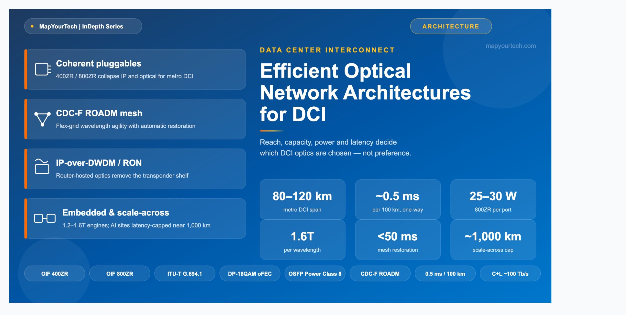
Scale-across is where the optical engineer lives, and its binding constraint is not optical reach. Coherent pluggables reach roughly 2,000 km at reduced rates, but distributed training generates synchronized all-reduce and all-gather collectives that stall on the slowest replica, so every additional 100 km of fiber adds about 0.5 ms of one-way propagation. Published demonstrations have kept distributed training within roughly 1,000 km even though the optics could go further. The light is not the limit; the speed of light is. This single fact reorders the whole design: latency is the ceiling, and reach margin beyond the latency budget is wasted.

The four networks of an AI cluster and their DCI distance classes A layered diagram showing scale-up copper inside a rack, scale-out optical GPU fabric, front-end Ethernet, and scale-across coherent DWDM DCI linking two sites, mapped to campus, metro, and regional distance bands. Site A (GPU campus) Site B (GPU campus) Scale-up (intra-rack) GPU–GPU over copper, ~130 TB/s bisection Copper saves ~20 kW/rack vs optics GPU GPU GPU GPU Scale-out (back-end fabric) 1 transceiver/GPU at 400G/800G InfiniBand or RoCEv2, all-optical Grey IMDD optics: SR/DR/FR DCI edge (core router) Coherent ZR/ZR+ pluggable → OLS FR4/LR4 grey on spine→core hop DCI edge (core router) Coherent ZR/ZR+ pluggable → OLS Mirror of Site A fabric Scale-out (back-end fabric) Remote GPU fabric, mirrored Scale-up (intra-rack) Remote GPU rack, mirrored Scale-across coherent DWDM DCI Campus ≤20 km, unamplified, 800LR class Coherent-Lite, lowest power/bit Metro 80–120 km, single amplified span 400ZR / 800ZR sweet spot Regional / scale-across to ~1,000–2,000 km coherent reach latency-capped at ~1,000 km Design note DCI begins at the DCI edge: the core router exits the fabric, a coherent pluggable enters the open line system, and the wave crosses the span. Everything below that line is data center fabric, not transport.
Figure 1: The four networks of an AI cluster and the DCI distance classes. Scale-up is copper inside the rack; scale-out and front-end are intra-site optical; scale-across is the coherent DWDM interconnect that this article addresses.

What DCI is not

A spine-leaf or Clos fabric is the packet answer inside a site, not the optical answer across one. It is excellent at non-blocking any-to-any connectivity within a building, but once traffic exits the leaf and spine it transitions into metro DCI, peering, and core constructs that a packet fabric does not replace. The four canonical optical topologies — point-to-point, ring, mesh, and spine-leaf/Clos — are primitives, and treating them that way prevents a common category error: a ring is economical for metro aggregation but does not behave like a flexible mesh under heavy any-to-any demand, and a spine-leaf fabric does not behave like a Reconfigurable Optical Add-Drop Multiplexer (ROADM) mesh across a metro. The skill is matching the primitive to the traffic, not forcing one primitive everywhere. For the broader transport hierarchy these primitives sit inside, the MapYourTech treatment of managed optical fiber networks for data centers is a useful companion.

Key terms, defined precisely

  • OSNR (Optical Signal-to-Noise Ratio): the ratio of signal power to amplified-spontaneous-emission noise power in a 0.1 nm (12.5 GHz) reference bandwidth, expressed in dB. It is the metric that decides whether a coherent link closes.
  • Coherent pluggable: a digital coherent optic with its Digital Signal Processor (DSP) integrated into a QSFP-DD or OSFP module, plugged directly into a router or switch faceplate.
  • Embedded transponder: a proprietary high-power optical engine on a dedicated line card inside a transport chassis, unconstrained by pluggable thermal limits.
  • Open line system (OLS): a DWDM photonic layer — amplifiers, ROADMs, mux/demux from one vendor — that accepts "alien wavelengths" from a different vendor's transponder, meeting only at documented add/drop optical contracts.
  • Alien wavelength: any channel whose transponder is not part of the OLS vendor's family; the OLS owns all photonic engineering, the transponder owns all bit-level behavior.

Takeaway: DCI is the scale-across network — the coherent interconnect between sites. Its design center is capacity, deterministic latency, and reliability at scale, and for distributed training the latency budget, not coherent reach, sets the outer distance limit at roughly 1,000 km.

3. Technical architecture

Four physical-layer architectures cover nearly all DCI builds, and each exists because a specific cost or capability boundary makes the others wrong for that case. They are not competing fashions; they are points on a curve of reach, capacity, wavelength agility, and operational ownership.

Point-to-point amplified DWDM

The traditional DCI build places a transponder or transceiver at each end, Erbium-Doped Fiber Amplifier (EDFA) or Raman amplification in between, and fixed or flexible mux/demux at the terminals. It is the lowest hop count, the simplest fault isolation, and the lowest operational friction. Its weakness is growth: every new adjacency consumes another wavelength, router port pair, or fiber pair, so an N-site build grows linearly in cost and operational load unless a higher-order fabric is introduced. A fiber cut takes the link down unless protection exists at the IP layer or via optical line protection, because there is no alternate optical path to reroute onto.

Premium Article — Free 20% Preview

Read the Full Analysis with Premium

The remaining 80% of this article — the design numbers, trade-offs and field guidance — is part of MapYourTech Premium, along with the full premium library, courses and professional tools.

Instant access · Cancel anytime · 48-hour trial available
Sanjay Yadav

Optical Communications & Network Automation Expert | Author of 3 Books for Optical Engineers | Founder, MapYourTech

Optical networking engineer with nearly two decades of experience across DWDM, OTN, coherent optics, submarine systems, and cloud infrastructure. Founder of MapYourTech.

Follow on LinkedIn


