
Erbium-Doped Fiber Amplifier Fundamentals
Complete Technical Guide from Basic Principles to Advanced Applications
Executive Summary
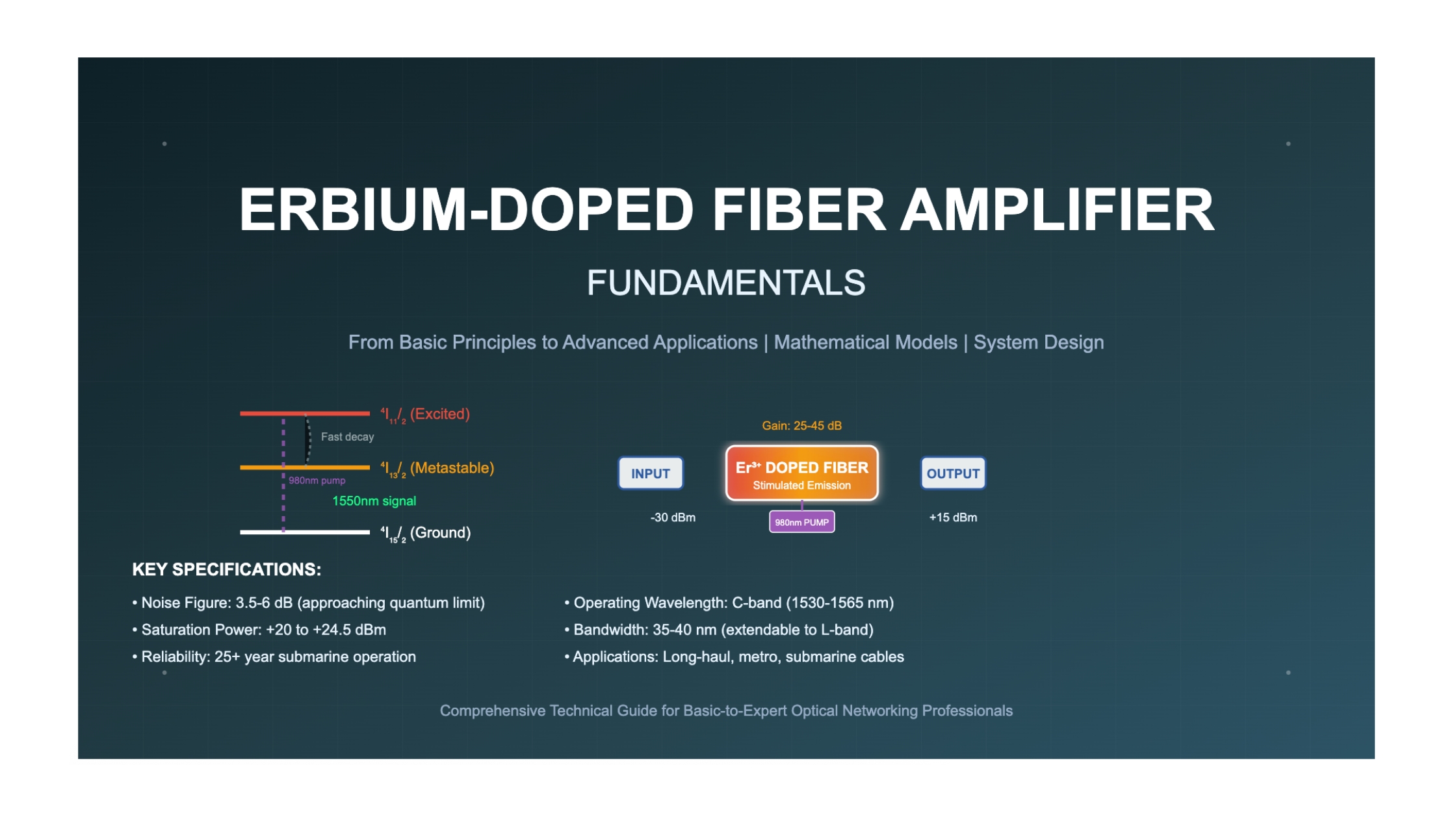
Bottom Line Up Front: Erbium-Doped Fiber Amplifiers (EDFAs) have revolutionized optical telecommunications by providing direct optical amplification in the 1550 nm low-loss window of silica fiber. Since their commercialization in the early 1990s, EDFAs have enabled long-haul transmission distances exceeding 10,000 km, submarine cable systems, and high-capacity wavelength division multiplexed (WDM) networks. With a theoretical minimum noise figure of 3 dB and gains exceeding 40 dB, EDFAs operate through stimulated emission from erbium ions (Er³⁺) pumped at 980 nm or 1480 nm wavelengths.
Key Performance Metrics: Commercial EDFAs achieve small-signal gains of 25-45 dB, noise figures of 3.5-6 dB, saturation output powers of +20 to +24.5 dBm, and gain bandwidths spanning 35-40 nm in the C-band (1530-1565 nm) and L-band (1565-1610 nm). The global EDFA market reached $1.24 billion in 2024 and is projected to grow to $2.05 billion by 2031, with a CAGR of 7.6%.
1.1 Genesis and Revolutionary Impact
The erbium-doped fiber amplifier stands as one of the most transformative innovations in modern telecommunications history. First demonstrated in 1987, EDFAs became commercially available by 1992, marking an unprecedented five-year trajectory from laboratory concept to widespread deployment. This rapid adoption was driven by the technology's ability to solve a fundamental limitation in optical fiber communications: the need for optical-to-electrical-to-optical (O-E-O) conversion for signal regeneration.
Prior to EDFA technology, long-haul optical transmission systems required electronic regenerators every 40-80 kilometers, creating complexity, cost, and reliability challenges. The introduction of EDFAs eliminated this requirement, enabling all-optical transmission over thousands of kilometers. The first submarine system to employ EDFA technology was TPC-5CN (Trans-Pacific Cable 5 Cable Network), which began operation in 1996, demonstrating the technology's maturity and reliability.
1.2 Fundamental Physics and Rare-Earth Ion Properties
The operational foundation of EDFAs lies in the unique spectroscopic properties of erbium ions (Er³⁺) when incorporated into silica glass hosts. Rare-earth ions possess the special characteristic that their atomic spectra are only moderately influenced by chemical bonds to the host glass matrix, because the electrons responsible for the spectra are in incomplete shells deep inside the atom. This property ensures consistent and predictable amplification characteristics across different glass compositions and environmental conditions.
Figure 1: Energy level diagram of erbium ions showing the three-level system that enables optical amplification. The long lifetime of the ⁴I₁₃/₂ metastable state (≈10 ms) compared to the ⁴I₁₁/₂ state (≈1 μs) creates the population inversion necessary for stimulated emission at 1550 nm.
The erbium energy level structure forms a quasi-three-level system with key transitions at 980 nm and 1480 nm for pumping, and 1550 nm for signal amplification. The metastable state ⁴I₁₃/₂ has a lifetime of approximately 10 milliseconds, which is sufficiently long to maintain population inversion under typical operating conditions.
1.3 Glass Host Materials and Doping Mechanisms
The choice of glass host material significantly influences EDFA performance characteristics. Silica-based glasses remain the dominant host due to their compatibility with standard telecommunications fiber and excellent mechanical properties. However, various co-dopants including aluminum, phosphorus, and germanium are used to modify the local environment around erbium ions, affecting absorption and emission cross-sections.
Critical Design Consideration: Erbium concentration must be carefully optimized to balance gain and avoid concentration quenching effects. Higher erbium doping levels (≥5,000 ppm) lead to poor amplifier efficiency due to interactions between neighboring Er³⁺ ions (ion pairs). This limitation drives the use of erbium-ytterbium co-doped configurations for high-power applications.
| Glass Host Type | Er³⁺ Concentration (ppm) | Absorption Cross-section @980nm (×10⁻²¹ cm²) | Emission Cross-section @1550nm (×10⁻²¹ cm²) | Key Characteristics |
|---|---|---|---|---|
| Alumino-silicate | 1000-3000 | 2.5 | 6.8 | High gain, good mechanical properties |
| Phospho-silicate | 2000-5000 | 3.2 | 7.5 | Enhanced solubility, broader gain spectrum |
| Germano-silicate | 1500-4000 | 2.8 | 6.2 | Reduced photodarkening, UV stability |
| Ternary AlPO₄-SiO₂ | 3000-8000 | 4.1 | 8.9 | Extended L-band operation, high efficiency |
1.4 Technological Evolution and Current Market Status
The EDFA market has experienced sustained growth driven by increasing bandwidth demands and network infrastructure expansion. The global EDFA market was valued at $1.24 billion in 2024 and is forecast to reach $2.05 billion by 2031, with a compound annual growth rate (CAGR) of 7.6%. This growth is fueled by several key factors:
- 5G Network Deployment: The rollout of 5G infrastructure requires high-capacity backhaul networks, driving demand for advanced optical amplification solutions.
- Data Center Expansion: The exponential growth of cloud computing services and establishment of large-scale data centers require efficient and high-capacity optical communication systems.
- Submarine Cable Systems: Increasing international bandwidth demands drive investment in transoceanic fiber optic cables, where EDFAs are essential for ultra-long-haul transmission.
- Wavelength Division Multiplexing: The adoption of dense WDM (DWDM) systems with 100+ channels necessitates sophisticated gain flattening and multi-band amplification capabilities.
High-resolution photograph of a modern EDFA module in a telecommunications equipment rack, showing the compact form factor and fiber connections, with soft blue LED status indicators illuminating the front panel against a dark background, shot with shallow depth of field to emphasize the precision engineering of optical components.
1.5 Contemporary Technological Challenges and Innovations
Recent developments focus on extending EDFA operation beyond traditional C-band limitations into extended L-band regions (1565-1610 nm), with research emphasizing signal-induced excited-state absorption (ESA) effects and optimization of fiber core compositions. Advanced configurations now include:
- Multi-Core EDFAs: Space-division multiplexing applications utilize multi-core or few-mode fibers, requiring amplifiers optimized for similar gain across different cores or fiber modes.
- Radiation-Resistant Designs: Aerospace and military applications demand EDFAs capable of operation in high-radiation environments.
- Cladding-Pumped Architectures: High-power applications employ erbium-ytterbium co-doped fibers with cladding pumping to achieve output powers exceeding 1 watt.
- Digital Control Systems: Modern EDFAs incorporate sophisticated control algorithms for automatic gain control, noise figure optimization, and gain flattening across multiple wavelength bands.
2.1 Fundamental Amplifier Architectures
EDFA system architecture encompasses three primary functional configurations, each optimized for specific operational requirements within optical transmission systems. The architectural choice fundamentally determines performance characteristics, cost, and system complexity.
Figure 2: EDFA system architectures showing the three primary configurations and pumping schemes. Each configuration is optimized for specific performance requirements: booster amplifiers for high output power, inline amplifiers for gain and low noise figure, and preamplifiers for maximum sensitivity.
| Configuration Type | Typical Input Power | Typical Output Power | Primary Performance Metric | Key Design Challenges |
|---|---|---|---|---|
| Booster Amplifier | 0 to +5 dBm | +17 to +24 dBm | Saturated output power | Nonlinear effects, SBS threshold |
| Inline Amplifier | -25 to -15 dBm | +10 to +17 dBm | Gain and noise figure balance | ASE accumulation, gain tilt |
| Preamplifier | -35 to -25 dBm | -10 to 0 dBm | Minimum noise figure | Signal-ASE beat noise |
2.2 Component-Level Architecture
A practical EDFA implementation requires careful integration of multiple optical and electronic components. Modern EDFAs incorporate built-in input and output isolators to protect the input laser source from amplified spontaneous emission or back reflections, as well as to prevent pump light from exiting the amplifier.
Figure 3: Detailed component-level architecture of a bidirectional pumped EDFA showing all essential elements including wavelength division multiplexers (WDM), isolators, optional gain flattening filter, monitoring photodiode, and control electronics.
3.1 Rate Equation Analysis
The fundamental behavior of EDFAs is governed by a system of coupled differential equations describing population dynamics, signal propagation, and amplified spontaneous emission. The analysis begins with the three-level rate equation model for erbium ions.
For the three-level erbium system:
dN₁/dt = -R₁₂ + R₂₁ + A₂₁N₂ + W₂₁N₂
dN₂/dt = R₁₂ - R₂₁ - A₂₁N₂ - W₂₁N₂ + R₃₂ - W₃₂N₂
dN₃/dt = R₁₃ - R₃₁ - R₃₂ + W₃₂N₂
with constraint: N₁ + N₂ + N₃ = Ntotal
Where the variables are defined as:
- N₁, N₂, N₃: Population densities in ground state ⁴I₁₅/₂, metastable state ⁴I₁₃/₂, and excited state ⁴I₁₁/₂ respectively [ions/m³]
- R₁₂, R₂₁: Stimulated transition rates between levels 1 and 2 due to signal photons [s⁻¹]
- R₁₃, R₃₁: Stimulated transition rates between levels 1 and 3 due to pump photons [s⁻¹]
- A₂₁: Spontaneous emission rate from level 2 to level 1 [s⁻¹]
- W₂₁, W₃₂: Non-radiative decay rates [s⁻¹]
3.2 Coupled Propagation Equations
The spatial evolution of signal and pump powers along the erbium-doped fiber is described by coupled propagation equations. For a signal at wavelength λs and pump at λp:
dPs/dz = (Γs/Aeff)(σe(λs)N₂ - σa(λs)N₁)Ps - αsPs
dPp/dz = ±(Γp/Aeff)(σa(λp)N₁ - σe(λp)N₂)Pp - αpPp
ASE power evolution:
dPASE±/dz = ±(Γs/Aeff)(σe(λs)N₂ - σa(λs)N₁)PASE± ± (Γs/Aeff)σe(λs)N₂hf∆f - αsPASE±
Parameter definitions for the propagation equations:
| Parameter | Symbol | Units | Typical Values | Physical Significance |
|---|---|---|---|---|
| Signal power | Ps | W | 10⁻⁶ to 10⁻¹ W | Optical power at signal wavelength |
| Pump power | Pp | W | 10⁻³ to 1 W | Optical power at pump wavelength |
| Effective area | Aeff | m² | 20-100 × 10⁻¹² m² | Mode overlap with doped region |
| Overlap factor | Γ | - | 0.7-0.95 | Spatial mode overlap with Er³⁺ ions |
| Emission cross-section | σe | m² | 6-8 × 10⁻²¹ m² | Probability of stimulated emission |
| Absorption cross-section | σa | m² | 2-4 × 10⁻²¹ m² | Probability of photon absorption |
3.3 Gain and Noise Figure Derivation
The small-signal gain coefficient for an EDFA under steady-state conditions is derived from the population inversion:
g(λ) = (Γ/Aeff)[σe(λ)N₂ - σa(λ)N₁]
Population inversion parameter:
nsp(λ) = N₂/[N₂ - (σa(λ)/σe(λ))N₁]
Small-signal gain (dB):
G0 = 10 log₁₀[exp(g(λ)L)]
Critical Performance Relationship: The noise figure of an EDFA is fundamentally limited by quantum mechanics. The theoretical minimum noise figure is 3 dB, achieved under complete population inversion conditions. Practical noise figures range from 3.5-6 dB depending on pump configuration and operating conditions.
NF = 2nsp[1 - 1/G] + 1/G
where G is the linear gain and nsp is the population inversion parameter
For complete inversion (N₁ → 0): nsp → 1, giving NFmin = 3 dB
3.4 Saturation Characteristics and Nonlinear Effects
As signal power increases, the EDFA exhibits gain saturation due to depletion of the population inversion. This behavior is characterized by the saturation power parameter:
Psat = (hfAeff)/(σeτ₂Γ)
Saturated gain:
Gsat = G₀/(1 + Pout/Psat)
where τ₂ is the metastable state lifetime (~10 ms)
Engineering Insight: Saturation power typically occurs around -30 dBm for input signal power in modern EDFAs. Beyond this point, output power increases logarithmically rather than linearly with input power, enabling automatic gain control functionality.
The mathematical framework presented here forms the foundation for EDFA design and optimization. These analytical models enable prediction of gain, noise figure, and saturation characteristics as functions of fiber parameters, pump power, and signal conditions. Advanced numerical simulation tools based on these equations are essential for modern amplifier development and system design.
4.1 Pump Source Selection and Optimization
The choice of pump wavelength fundamentally determines EDFA performance characteristics, efficiency, and complexity. The two most efficient pump wavelengths for erbium amplification are 980 nm and 1480 nm, each offering distinct advantages and trade-offs. Modern high-performance EDFAs often employ both wavelengths in hybrid pumping schemes to optimize different performance metrics simultaneously.
| Pump Wavelength | Key Advantages | Primary Limitations | Noise Figure Impact | Optimal Applications |
|---|---|---|---|---|
| 980 nm | • Lower noise figure • No ESA at signal wavelength • High quantum efficiency |
• Temperature sensitive • Requires wavelength stabilization • More expensive diodes |
3.0-4.5 dB typical | Preamplifiers, low-noise applications |
| 1480 nm | • Temperature insensitive • No wavelength stabilization • Lower pump power required |
• Higher noise figure • Excited state absorption • Ground state depletion |
4.5-6.5 dB typical | Power amplifiers, cost-sensitive designs |
| Hybrid (980+1480) | • Optimized noise and power • Enhanced gain bandwidth • Improved efficiency |
• Increased complexity • Higher cost • Dual control systems |
3.5-5.0 dB typical | High-performance inline amplifiers |
Quantum conversion efficiency for pump absorption:
ηquantum = (λp/λs) × (Psignal,out - Psignal,in)/Ppump,absorbed
For 980 nm pump: ηmax = 980/1550 ≈ 63%
For 1480 nm pump: ηmax = 1480/1550 ≈ 95%
4.2 Fiber Design and Geometric Optimization
Erbium-doped fiber design involves complex trade-offs between gain efficiency, bandwidth, and manufacturing complexity. The effective mode area must be minimized to maximize pump intensity and gain per unit length, while maintaining single-mode operation and acceptable splice losses.
Figure 4: Erbium-doped fiber core designs showing evolution from simple step-index to advanced double-clad configurations. Each design offers specific advantages for different performance requirements and power levels.
4.3 Multi-Stage Amplifier Architectures
High-performance EDFAs often employ multi-stage architectures to optimize the trade-off between gain, noise figure, and output power. Multi-stage configurations enable insertion of gain flattening filters, dispersion compensation, and variable optical attenuators while maintaining optimal noise performance.
• First stage: Low-noise amplification
• Mid-stage: Filtering/compensation
• Second stage: Power amplification
NF: 4.5-5.5 dB
Gain: 30-40 dB
• Enhanced optimization flexibility
• Multiple filtering opportunities
• Superior gain control
NF: 5.0-6.0 dB
Gain: 35-45 dB
• Distributed + lumped gain
• Extended reach capability
• Enhanced OSNR performance
NF: 3.5-4.5 dB
Gain: 25-35 dB
5.1 Gain Flattening Techniques
Wavelength-dependent gain variation poses significant challenges in WDM systems, particularly in cascaded amplifier chains. Gain flatness is critical when many EDFAs are concatenated in optical transmission lines, as gain variation accumulates and results in large signal power differences between WDM channels.
Gain Peaking Phenomenon: In cascaded amplifier systems, the gain spectrum naturally evolves toward longer wavelengths due to gain saturation effects. For a series of twelve cascaded amplifiers, the gain peak occurs at approximately 1558 nm, with the peak narrowing with each stage of amplification.
Figure 5: Four primary approaches to gain flattening in EDFAs: optical filtering, fiber composition optimization, dual-band operation, and dynamic gain control. Each method addresses different aspects of spectral gain uniformity.
5.2 Noise Figure Optimization
Noise figure optimization requires careful balance of multiple design parameters. The fundamental relationship between population inversion and noise performance drives design decisions throughout the amplifier architecture.
Population inversion optimization:
nsp,opt = 1 + (N₁/N₂) × (σa/σe)
Optimal pump power for minimum noise figure:
Ppump,opt = Psat × ln(Gtarget)/LEDF
Multi-stage noise figure:
NFtotal = NF₁ + (NF₂-1)/G₁ + (NF₃-1)/(G₁×G₂) + ...
Optimization Strategy: 980 nm pumped devices offer significant advantages in terms of quantum conversion efficiency compared to 1480 nm pumped amplifiers. For preamplifier applications, 980 nm pumping typically achieves noise figures of 3.5-4.5 dB, approaching the quantum limit.
5.3 Advanced Pumping Schemes
Contemporary high-performance EDFAs employ sophisticated pumping architectures to optimize different performance metrics simultaneously. Cladding-pumped configurations using erbium-ytterbium co-doped fiber amplifiers (EYDFAs) enable high-power operation exceeding 500 mW output power.
| Pumping Configuration | Typical Performance | Key Benefits | Implementation Complexity |
|---|---|---|---|
| Forward Pumping | NF: 4-6 dB Gain: 25-35 dB |
• Simple implementation • Good efficiency • Low cost |
Low |
| Backward Pumping | NF: 5-7 dB Gain: 20-30 dB |
• Pump isolation • Reduced back-reflection • Better pump efficiency |
Medium |
| Bidirectional Pumping | NF: 3.5-5 dB Gain: 30-40 dB |
• Highest gain • Optimized inversion • Excellent performance |
High |
| Cladding Pumping | Output: >1W Efficiency: >50% |
• Very high power • Multimode pumps • Excellent efficiency |
Very High |
Design Trade-off Alert: Bidirectional pumping configurations show the highest gain value, while forward pumping presents the lowest noise figure for each pump wavelength. System requirements must carefully balance these competing performance metrics based on application-specific priorities.
5.4 Temperature and Environmental Optimization
EDFA performance exhibits significant temperature dependence, particularly for 980 nm pumped configurations. Environmental optimization requires careful thermal management and may include active temperature control systems.
Pump laser wavelength drift:
dλ/dT ≈ 0.3 nm/°C (980 nm)
dλ/dT ≈ 0.6 nm/°C (1480 nm)
Gain temperature coefficient:
dG/dT ≈ -0.01 to -0.03 dB/°C
Noise figure temperature sensitivity:
dNF/dT ≈ 0.005-0.015 dB/°C
The implementation strategies outlined in this section form the foundation for practical EDFA design and deployment. Modern EDFAs achieve remarkable performance through careful optimization of pump sources, fiber design, multi-stage architectures, and environmental control. These techniques enable the construction of amplifiers that approach theoretical performance limits while maintaining the reliability and cost-effectiveness required for large-scale telecommunications deployment.
6.1 Submarine Cable Systems
Submarine optical cable systems represent the most demanding application environment for EDFAs, requiring unprecedented reliability, performance, and longevity. By 1996, erbium-doped fiber amplifiers were in commercial use in undersea links, particularly TPC-5 and TAT-12/13, increasing capacity nearly tenfold over previous generation cables. These systems demand 25-year operational lifetimes with no maintenance access, driving extreme reliability requirements.
System Overview: TAT-14, deployed in 2001, spans 15,428 km between the United States, United Kingdom, France, Netherlands, Denmark, and Germany. The system employs over 600 submarine EDFAs operating continuously for more than two decades.
Technical Specifications:
- Amplifier spacing: 50-60 km intervals
- Individual EDFA gain: 15-18 dB per repeater
- Cumulative gain: >9,000 dB total system gain
- Wavelength channels: 160 DWDM channels (ITU grid)
- Total capacity: 3.2 Tb/s initial, upgraded to 40+ Tb/s
Key Performance Achievements: The system demonstrates EDFA reliability with <0.01% failure rate over 20+ years, validating submarine-grade design approaches including radiation-hardened components, hermetic sealing, and redundant pump systems.
Figure 6: Submarine cable system showing EDFA repeater placement every 50-60 km along the ocean floor. Each repeater contains multiple EDFAs for different fiber pairs and backup systems, achieving >99.99% reliability over 25-year design lifetimes.
| Submarine System Generation | Deployment Period | EDFA Technology | Typical Capacity | Key Innovations |
|---|---|---|---|---|
| Gen 1 (TPC-5) | 1996-2000 | Basic single-stage EDFAs | 5-10 Gb/s | First submarine EDFA deployment |
| Gen 2 (TAT-14) | 2000-2005 | Multi-stage, gain flattened | 40-160 Gb/s | WDM optimization, C-band |
| Gen 3 (Atlantic Crossing) | 2005-2010 | C+L band, Raman hybrid | 1.28-3.84 Tb/s | Extended bandwidth, coherent |
| Gen 4 (Current) | 2010-Present | Multi-core, SDM ready | 10-200+ Tb/s | Space division multiplexing |
6.2 Terrestrial Long-Haul Networks
Terrestrial long-haul networks present different challenges compared to submarine systems, with requirements for flexibility, upgradeability, and cost optimization. MCI purchased and began installation of 500 optical amplifiers in 1993, representing one of the first large-scale terrestrial EDFA deployments.
6.3 Data Center Interconnect Applications
The exponential growth of cloud computing services and establishment of large-scale data centers require efficient and high-capacity optical communication systems, where EDFAs play a crucial role in enabling high-bandwidth interconnections between geographically distributed facilities.
Application: Major cloud service provider connecting data centers across North America with 400G and 800G coherent links.
EDFA Requirements:
- Ultra-low latency amplification (<5 μs)
- High saturation power (+23 dBm) for coherent signals
- Excellent gain flatness (±0.5 dB across C-band)
- Rapid provisioning and automated management
- Space and power efficiency for colocation facilities
Solution Architecture: Compact 1U rack-mount EDFAs with integrated monitoring, automatic gain control, and remote management capabilities. Each amplifier supports 96-channel DWDM with per-channel power monitoring and dynamic gain equalization.
Performance Results: Achieved >99.999% availability with <50ms protection switching, supporting aggregate capacities exceeding 76.8 Tb/s per fiber pair across spans up to 500 km.
6.4 Cable Television Distribution Networks
Hybrid fiber-coax cable television networks employ EDFAs to extend the number of homes served, representing a significant analog application domain where linearity and noise performance are critical for signal quality.
Analog Performance Requirements: Cable TV applications demand exceptional linearity to minimize composite second-order (CSO) and composite triple-beat (CTB) distortions. EDFAs for analog applications typically operate at reduced gain and output power to maintain <-60 dBc distortion levels across 77+ TV channels.
| Application Domain | Primary Performance Metric | Typical EDFA Configuration | Key Design Challenges |
|---|---|---|---|
| Submarine Cables | Reliability (25-year lifetime) | Dual-stage, redundant pumps | Zero maintenance, radiation hardening |
| Long-Haul Terrestrial | OSNR and reach optimization | Raman-EDFA hybrid | Nonlinear effects, dispersion management |
| Metro/Regional | Cost-performance balance | Single-stage, automated | Flexible add/drop, rapid provisioning |
| Data Center Interconnect | High power, low latency | Compact, high-saturation | Power efficiency, thermal management |
| Cable TV Distribution | Analog linearity (CSO/CTB) | Low-power, linear operation | Distortion minimization, dynamic range |
7.1 Space Division Multiplexing Systems
Space-division multiplexing (SDM) applications utilize multi-core or few-mode fibers, requiring amplifiers optimized for similar gain across different cores or fiber modes. This represents a fundamental shift toward three-dimensional optical networking to address the approaching capacity limits of single-mode fiber systems.
Recent Achievement: Cladding-pumped SDM erbium-doped fiber amplifier consisting of six uncoupled multimode erbium-doped cores, where each core supports three spatial modes, enabling amplification of 18 spatial channels simultaneously with >20 dBm total output power per core and <7 dB noise figure over the C-band.
7.2 Extended L-Band and S-Band Operation
The drive for increased capacity pushes EDFA operation beyond traditional C-band boundaries. Recent research focuses on extending EDFA operation to cover extended L-band regions (1565-1610 nm), with emphasis on signal-induced excited-state absorption effects and optimization of fiber core compositions with appropriate co-dopants.
Future Research Directions:
- Novel Co-Dopants: Investigation of ytterbium (Yb), cerium (Ce), and yttrium (Y) co-doping for extended bandwidth and improved efficiency
- Pump Optimization: Development of new pump wavelengths and configurations for S-band (1460-1530 nm) amplification
- Radiation Resistance: Enhanced radiation-resistant EDFAs for aerospace and satellite applications
- Quantum Applications: EDFAs optimized for quantum communication systems with ultra-low noise and preserved quantum states
7.3 Underwater and Aerospace Applications
The demanding conditions of underwater environments, characterized by high pressures, temperature fluctuations, and corrosive agents, necessitate specialized EDFA designs with exceptional robustness, advanced thermal management systems, and protective coatings.
Application: Ocean observatory network with fiber optic connections to deep-sea research stations at depths exceeding 6000 meters.
Environmental Challenges:
- Pressure: >600 atmospheres (60 MPa)
- Temperature: 2-4°C with minimal variation
- Corrosive seawater environment
- 20+ year deployment without maintenance
- Seismic activity and ocean current stresses
EDFA Design Solutions: Titanium pressure housings, redundant pump systems, low-temperature optimized erbium-doped fiber, and comprehensive environmental sealing. Power efficiency optimized for limited electrical power from surface-supplied constant current.
Performance Achievement: Successfully operating for >15 years with 99.97% uptime, supporting real-time data transmission from seafloor sensors and autonomous underwater vehicles.
7.4 Industry Trends and Market Evolution
The EDFA market continues evolving driven by several key technological and economic trends. Growing demand for video streaming and content delivery necessitates robust and high-bandwidth optical communication systems, creating opportunities for EDFA technology in content distribution networks.
Figure 7: EDFA market evolution showing technology development trends from basic amplification in the 1990s to advanced SDM and quantum-ready systems projected for the 2030s. Market growth reflects increasing bandwidth demands and technological sophistication.
The practical implementations and case studies examined in this section demonstrate the remarkable versatility and reliability of EDFA technology across diverse application domains. From the extreme demands of 25-year submarine deployments to the rapid evolution of data center interconnects, EDFAs have proven their fundamental importance to modern optical communications infrastructure.
8.1 Quantum-Limited Performance Enhancement
The pursuit of quantum-limited performance in EDFAs represents one of the most fundamental research challenges. While theoretical noise figure limits of 3 dB have been established, practical implementations face additional constraints from excited-state absorption, concentration quenching, and pump-signal interactions that prevent achievement of ideal performance.
Research Objectives:
- Sub-3dB noise figure achievement through quantum correlation
- Squeezed light generation in amplification process
- Entanglement preservation for quantum communications
Technical Challenges: Decoherence effects, thermal noise, pump intensity fluctuations
Research Objectives:
- Coherent pumping for reduced quantum noise
- Multi-frequency pump optimization
- Adiabatic population transfer techniques
Technical Challenges: Pump coherence requirements, phase stability, complexity
Research Objectives:
- Ultra-low phonon energy hosts
- Engineered local field environments
- Nanostructured erbium incorporation
Technical Challenges: Material compatibility, fabrication complexity, cost scaling
8.2 Space Division Multiplexing Amplification
The transition to space division multiplexing represents a paradigm shift requiring fundamental advances in amplifier design. Current SDM erbium-doped fiber amplifiers achieve amplification of 18 spatial channels simultaneously, but future systems will require hundreds of spatial modes with unprecedented uniformity and crosstalk suppression.
SDM Amplification Challenges:
- Mode-Dependent Gain: Achieving <0.1 dB gain variation across 100+ spatial modes
- Inter-Core Crosstalk: Suppressing crosstalk to <-40 dB between adjacent cores
- Pump Distribution: Uniform pumping across large multi-core fiber cross-sections
- Thermal Management: Heat dissipation in high-density core configurations
- Nonlinear Mitigation: Managing inter-core nonlinear interactions at high power levels
SDM Amplifier Design Equations:
Mode-dependent gain variation: σG = √[Σᵢ(Gᵢ - Ḡ)²/N]
Inter-core crosstalk: Xcore = 10log₁₀[Pcoupled/Psignal]
Pump efficiency: ηSDM = Σᵢ(Pout,i - Pin,i)/Ppump,total
8.3 Artificial Intelligence Integration
The integration of artificial intelligence and machine learning represents a transformative opportunity for EDFA optimization and control. Neural networks are being employed to map noise figure and gain flatness over power masks, reducing characterization time significantly while maintaining high accuracy with errors as low as 0.1 dB.
| AI Application Domain | Current Capabilities | Research Frontiers | Expected Impact |
|---|---|---|---|
| Performance Prediction | Gain and NF mapping | Real-time optimization algorithms | 50% reduction in characterization time |
| Failure Prediction | Trend analysis | Predictive maintenance models | 90% reduction in unplanned outages |
| Adaptive Control | Static compensation | Dynamic environment adaptation | 30% improvement in performance stability |
| Design Optimization | Parameter sweeps | Multi-objective evolutionary algorithms | Automated design synthesis |
8.4 Extended Bandwidth Operation
Future optical systems will demand amplification across increasingly wide spectral ranges. Research emphasizes extending EDFA operation beyond traditional C-band limitations into extended L-band regions (1565-1610 nm), with focus on signal-induced excited-state absorption effects and optimization of fiber core compositions.
Figure 8: Extended bandwidth EDFA research roadmap showing evolution from current 35 nm C-band operation to projected 150 nm S+C+L band capability by 2035. Key technical challenges and research approaches are identified for each development phase.
9.1 Fundamental Physical Limitations
Despite remarkable technological advances, EDFAs face fundamental physical limitations that constrain ultimate performance. Understanding these limitations is crucial for realistic system design and identifying areas where alternative technologies may be necessary.
Quantum-Limited Noise Figure: The theoretical minimum noise figure of 3 dB represents an absolute quantum mechanical limit that cannot be overcome through conventional amplification. Practical noise figures of 3.5-6 dB in commercial systems reflect additional noise sources including spontaneous emission, pump noise transfer, and thermal effects.
Concentration Quenching Effects: Higher erbium doping levels (≥5,000 ppm) lead to poor amplifier efficiency due to interactions between neighboring Er³⁺ ions. This fundamental limitation requires careful balance between gain per unit length and amplifier efficiency, often necessitating longer fiber lengths or alternative approaches like erbium-ytterbium co-doping.
| Limitation Category | Physical Origin | Typical Impact | Mitigation Strategies |
|---|---|---|---|
| Noise Figure Floor | Quantum mechanics | NF ≥ 3 dB theoretical limit | Optimal population inversion, 980nm pumping |
| Saturation Power | Finite metastable lifetime | Output power limiting | Larger mode area, cladding pumping |
| Bandwidth Constraints | Erbium cross-section spectrum | Limited to ~100 nm maximum | Hybrid amplifiers, novel hosts |
| Temperature Sensitivity | Pump laser wavelength drift | Performance variation ±0.1 dB/°C | Temperature control, 1480nm pumping |
| Nonlinear Effects | High optical intensity | Signal distortion, crosstalk | Power management, dispersion control |
9.2 System-Level Trade-offs
Real-world EDFA implementations require careful navigation of multiple competing performance metrics. These trade-offs become increasingly complex in advanced systems with demanding requirements across multiple dimensions simultaneously.
Multi-Objective Optimization Framework:
Objective function: F = w₁·G + w₂·(1/NF) + w₃·Psat + w₄·(1/Cost) - w₅·Complexity
Subject to constraints: G ≥ Gmin, NF ≤ NFmax, Psat ≥ Pmin
Where wi are application-specific weighting factors
Design Trade-off Example: Bidirectional pumping configurations show the highest gain values, while forward pumping presents the lowest noise figure. System designers must carefully balance these competing performance metrics based on specific application requirements, cost constraints, and reliability targets.
9.3 Emerging Competitive Technologies
While EDFAs remain dominant in the 1550 nm region, the only competitors to erbium-doped fiber amplifiers are Raman amplifiers, which benefit from development of higher power pump lasers. Understanding competitive landscape evolution is essential for strategic technology planning.
Advantages:
- Distributed gain in transmission fiber
- Lower noise figure potential
- Bandwidth flexibility
Limitations: High pump power requirements, complexity, cost
Advantages:
- Compact integration
- Fast response time
- Electrical control
Limitations: High noise figure, polarization dependence, saturation
Advantages:
- Ultra-wide bandwidth
- Phase-sensitive operation
- Quantum noise benefits
Limitations: Complexity, pump requirements, stability
Current State of Technology: Erbium-doped fiber amplifiers have achieved remarkable maturity, with commercial implementations approaching theoretical performance limits in many aspects. Noise figures within 0.5 dB of quantum limits, gains exceeding 40 dB, and reliability demonstrated over 25-year submarine deployments validate the technology's fundamental soundness.
Key Performance Achievements:
- Noise figure: 3.5-6 dB (approaching 3 dB quantum limit)
- Gain: 25-45 dB with excellent stability
- Saturation power: +20 to +24.5 dBm in compact packages
- Bandwidth: 35-40 nm in C-band, extending to 80+ nm with C+L operation
- Reliability: >99.99% availability in submarine systems over 20+ years
Market Impact: The global EDFA market reached $1.24 billion in 2024 with projected growth to $2.05 billion by 2031, driven by 5G deployment, data center expansion, and increasing bandwidth demands. This growth trajectory reflects the technology's continued central importance to global telecommunications infrastructure.
10.1 Strategic Technology Roadmap
The future evolution of EDFA technology will be driven by three primary forces: the physical limits of single-mode fiber capacity, the emergence of space division multiplexing, and the integration of artificial intelligence for optimization and control. Each driver presents both opportunities and challenges for continued technology advancement.
2025-2030 Development Priorities:
- Extended Bandwidth: Achieving practical S+C+L band operation (1460-1610 nm) with <1 dB gain ripple
- SDM Integration: Multi-core amplifiers supporting 50+ spatial channels with uniform performance
- AI-Driven Optimization: Real-time adaptive control systems reducing operational costs by 30-50%
- Quantum Compatibility: Amplifiers preserving quantum states for emerging quantum network applications
- Environmental Sustainability: Power efficiency improvements and recyclable materials integration
10.2 Research Investment Priorities
Strategic research investment should focus on areas where fundamental breakthroughs can enable new system capabilities rather than incremental improvements to existing technology. The highest-impact research areas combine basic physics understanding with practical engineering solutions.
| Research Area | Investment Priority | Expected Timeline | Potential Impact |
|---|---|---|---|
| Quantum-Enhanced Amplification | High | 5-10 years | Sub-quantum-limit noise, entanglement preservation |
| Novel Host Materials | Medium-High | 3-7 years | Extended bandwidth, improved efficiency |
| AI/ML Integration | High | 2-5 years | Autonomous optimization, predictive maintenance |
| SDM Amplifier Architecture | Very High | 3-8 years | 100x capacity increase potential |
| Environmental Hardening | Medium | 2-4 years | Space, underwater, extreme environment operation |
Related Articles on MapYourTech


