

Generic selectors
Exact matches only
Search in title
Search in content
Post Type Selectors
Articles
lp_course
lp_lesson
Back
HomeCoherent OpticsFiber Bend Loss: Macrobend vs. Microbend
Fiber Bend Loss: Macrobend vs. Microbend

Fiber Bend Loss: Macrobend vs. Microbend

Last Updated: April 2, 2026
21 min read
82
Fiber Bend Loss: Macrobend vs. Microbend — MapYourTech

Fiber Bend Loss: Macrobend vs. Microbend

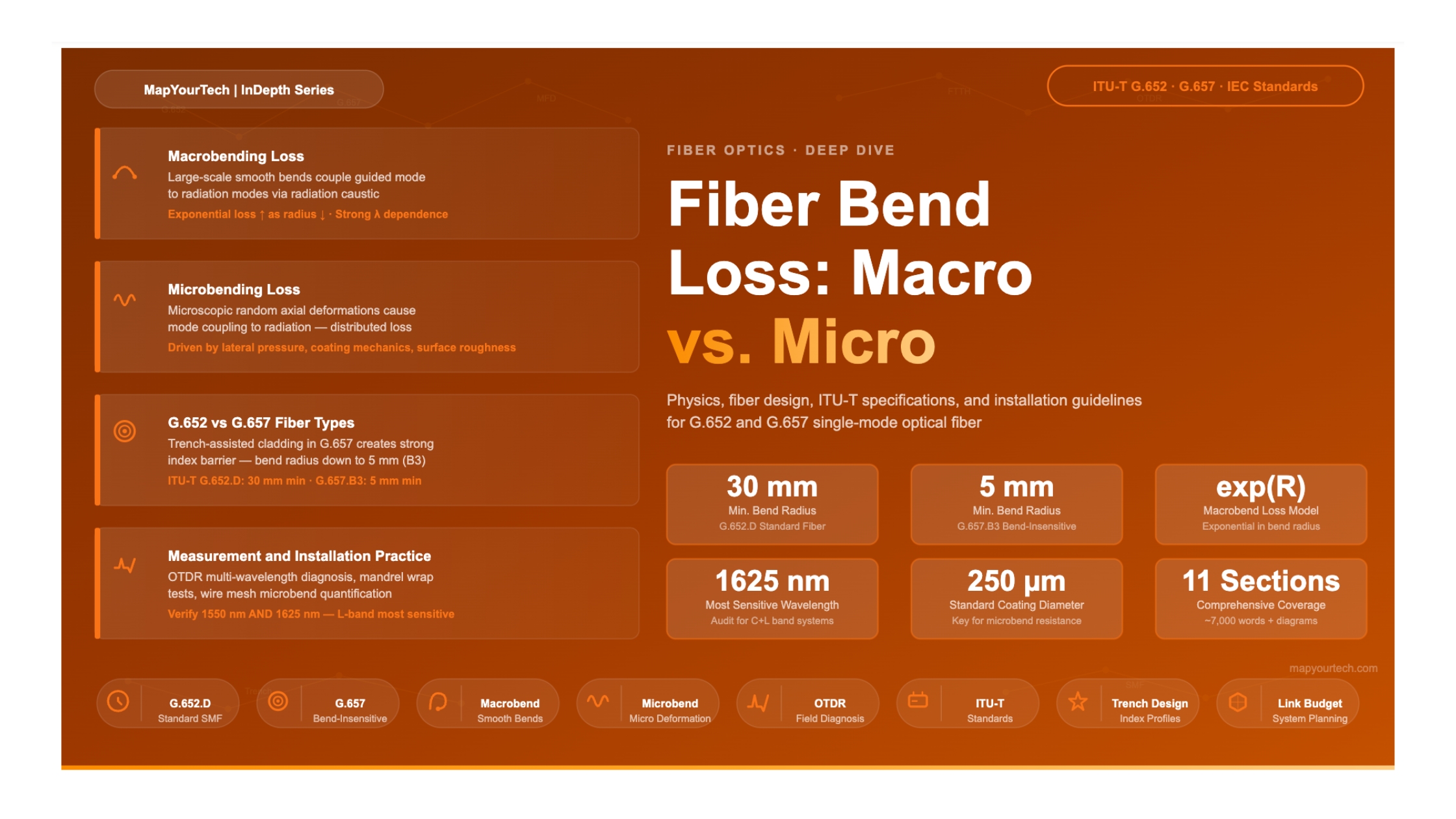
Physics, fiber-type specifications, ITU-T standards, and practical installation guidelines — a comprehensive engineering reference for optical network professionals

Section 1

Introduction

Bending loss is one of the most practically important impairments in the deployment and operation of optical fiber networks. Every time a fiber is routed around a corner, coiled inside a splice enclosure, pulled through a narrow conduit, or compressed inside a cable structure, it experiences a geometric perturbation that causes some of the guided optical power to radiate away from the core. Depending on the scale and nature of that perturbation, the loss mechanism is categorized as either macrobending or microbending — two physically distinct phenomena governed by different physics and requiring different mitigation strategies.

For long-haul transmission systems operating in the 1550 nm window, even fractions of a decibel per kilometer of additional bend-induced attenuation can close the power margin and force costly network redesigns. In submarine cable systems, where the fiber is locked inside a pressurized cable structure for decades, the distinction between macrobend and microbend sensitivity determines whether the cable will maintain stable attenuation over its design life. In access networks deploying Fiber-to-the-Home (FTTH), fibers must survive tight bends inside walls, conduits, and customer premises with bend radii as small as 5 mm.

This article provides a thorough engineering treatment of both loss mechanisms: their physical origins, the mathematical models that describe them, the fiber design parameters that govern sensitivity, the ITU-T specifications for G.652 and G.657 fiber types, and the installation practices that keep bend loss within acceptable limits in real deployments.

30 mm
Min. bend radius — G.652 standard fiber
7.5 mm
Min. bend radius — G.657.B3 bend-insensitive
<0.1 dB
Typical splice loss target (fusion)
1550 nm
Most sensitive wavelength for bend loss
Section 2

Fundamental Principles of Bend Loss

To understand why bending causes optical power to escape the fiber core, it is necessary to revisit the mechanism of light guidance itself. In a single-mode fiber, the guided mode is confined to the core because the refractive index of the core (nco) is slightly higher than that of the surrounding cladding (ncl), creating the condition for total internal reflection. The mode field is not entirely contained within the physical core boundary — an evanescent tail extends into the cladding, decaying exponentially with radial distance.

When the fiber is bent, the effective refractive index distribution seen by the propagating mode becomes asymmetric. On the outer side of the bend, the phase velocity of the mode field must increase to keep up with the field on the straight portion. At a certain radial distance from the center of the bent fiber, the required phase velocity exceeds the speed of light in the cladding material. Beyond this critical radius — often called the radiation caustic — the mode can no longer be guided and radiates away as unbound cladding or radiation modes. The result is measurable optical power loss.

2.1 Macrobending Loss

Macrobending refers to large-scale, smooth bends of the fiber with a well-defined, uniform bend radius — the kind that occurs when a fiber is routed around a corner, wound on a spool, or looped inside a splice tray. The characteristic scale of a macrobend is millimeters to centimeters, far larger than the fiber diameter.

Macrobending loss αB increases exponentially with decreasing bend radius and with increasing wavelength. A widely used analytical model expresses the macrobend loss coefficient as:

Macrobend Loss Model
α_B  C₁ · exp(-C₂ · R)

Where:
  α_B  = macrobend loss coefficient (dB/m or dB/turn)
  C₁   = coefficient dependent on fiber parameters (V-number, MFD)
  C₂   = coefficient proportional to (Δ/λ²) where Δ is core-cladding 
           index difference and λ is wavelength
  R    = bend radius (mm)

Key dependencies:
  — Loss increases exponentially as R decreases
  — Loss increases with longer wavelengths (weaker confinement)
  — Loss decreases with larger Δ (stronger confinement)
  — Loss decreases with smaller MFD (more confined mode)

This exponential relationship has a critical practical implication: there is a characteristic bend radius below which the loss rises steeply — often called the critical bend radius. For standard G.652 single-mode fiber, this threshold is typically in the range of 25–35 mm for the 1550 nm window. Bending below this radius can introduce losses that are orders of magnitude larger than losses at modest radii above the threshold.

The wavelength dependence of macrobend loss is pronounced. At 1625 nm (the L-band edge), macrobend loss can be several times larger than at 1310 nm for the same bend radius. This is because longer-wavelength modes have larger evanescent tails that extend further into the cladding, making them more susceptible to radiation when the fiber is bent.

Physical Insight: Why Longer Wavelengths Are More Sensitive

At longer wavelengths, the normalized frequency V-number decreases, which means the mode field is less tightly confined to the core. The evanescent field extending into the cladding becomes larger and reaches further from the core boundary. When the fiber is bent, this extended evanescent tail interacts with the radiation caustic at a smaller bend radius, causing the mode to lose confinement at larger radii than shorter-wavelength modes. This is why bend loss specifications in ITU-T recommendations are always evaluated at 1550 nm and 1625 nm, and why L-band systems require particular attention to bend management.

2.2 Microbending Loss

Microbending is a fundamentally different mechanism. Rather than a smooth, intentional bend, microbending consists of microscopic, random, longitudinally varying deformations of the fiber axis — perturbations on a scale of micrometers to fractions of a millimeter. These deformations arise from manufacturing imperfections, the mechanical interaction of the fiber with rough surfaces (such as other fibers in a bundle, sand, or the texture of a cable component), and thermally induced stress.

The physical mechanism of microbending loss is mode coupling. The spatial frequency spectrum of the random axial perturbations contains components that satisfy the phase-matching condition between the fundamental guided mode (LP01) and higher-order modes or radiation modes. When this coupling occurs, energy is transferred from the guided mode to unguided modes and is effectively lost from the transmitted signal.

The degree of microbending can be characterized by the power spectral density Φ of the lateral fiber deformation. A model used for submarine fiber engineering expresses this as:

Microbend Power Spectral Density Model
Φ = f₀ · x_s² · σ / (H_f^1.125 · D₀^0.25μ · H₀^0.25μ-0.125)

Where:
  f₀   = lateral pressure applied on the fiber
  x_s  = primary spring constant  = 2E_p x_g / (x_p - x_g)
  σ   = standard deviation of the rough surface
  H_f  = stiffness of the fiber glass = π E_g x_g⁴ / 4
  D₀  = lateral rigidity = E_p + E_s(1 - r_p/r_s)³
  H₀  = secondary stiffness = π E_s(r_s⁴ - r_p⁴) / 4
  μ   = surface deformation spectrum parameter (typically μ = 3)

Mitigation directions from the model:
  — Lower Young's modulus of primary coating → reduces Φ
  — Higher Young's modulus of secondary coating → reduces Φ
  — Larger coating diameter → reduces Φ
  — Larger glass diameter would worsen Φ (inverse 8th power dependence)

Unlike macrobending, microbending loss is determined not only by the glass refractive index profile but also substantially by the mechanical properties of the polymer coating surrounding the fiber. A soft primary coating buffers external mechanical stresses, while a stiffer secondary coating provides structural rigidity. The interplay between these two layers, their respective Young's moduli, and the total coating diameter determines how effectively the coating system protects the glass from microbending-inducing deformations.

Certain glass index profile designs — particularly trench-assisted and W-shaped cladding structures — can also reduce microbending loss by reducing the coupling coefficient between the fundamental mode and radiation modes, even when the physical deformation of the fiber axis remains the same.

Figure 1: Macrobend Attenuation vs. Bend Radius at 1550 nm — G.652 vs. G.657.A2
Figure 1: Qualitative representation of macrobend loss behavior. G.657.A2 shows substantially lower loss at small radii due to trench-assisted cladding design. Actual values depend on specific fiber lot and measurement conditions.
Section 3

Fiber Design Parameters Governing Bend Sensitivity

Several fundamental design parameters of a single-mode fiber determine its sensitivity to both macrobending and microbending. Understanding these parameters is essential for selecting the right fiber type for a given deployment scenario and for evaluating fiber datasheets intelligently.

Premium Article — Free 21% Preview

Read the Full Analysis with Premium

The remaining 79% of this article — the design numbers, trade-offs and field guidance — is part of MapYourTech Premium, along with the full premium library, courses and professional tools.


Instant access · Cancel anytime · 48-hour trial available
Sanjay Yadav

Optical Communications & Network Automation Expert | Author of 3 Books for Optical Engineers | Founder, MapYourTech

Optical networking engineer with nearly two decades of experience across DWDM, OTN, coherent optics, submarine systems, and cloud infrastructure. Founder of MapYourTech.

Follow on LinkedIn

You May Also Like

15 min read 6 0 Like Connector Types and Their Loss Budgets: SC, LC, MPO Skip to main content MapYourTech...
  • Free
  • July 11, 2026
16 min read 6 0 Like Cooled vs Uncooled Lasers: The Pluggable Power Trade-off Skip to main content MapYourTech |...
  • Free
  • July 11, 2026
16 min read 7 0 Like Automation Blast Radius: Scoping What a Bad Intent Can Touch Skip to main content...
  • Free
  • July 11, 2026

Course Title

Course description and key highlights

Course Content

Course Details
