
Generic selectors
Exact matches only
Search in title
Search in content
Post Type Selectors
Articles
lp_course
lp_lesson
Back
HomeCoherent OpticsInside the Coherent Receiver: Optical Front End to Symbol Decisions
Inside-the-Coherent-Receiver-optical-front-end-featured-image_09_07_2026_20_26_21

Inside the Coherent Receiver: Optical Front End to Symbol Decisions

54 min read
18
Inside the Coherent Receiver: Optical Front End
Skip to main content
MapYourTech | InDepth Series

Inside the Coherent Receiver: Optical Front End to Symbol Decisions

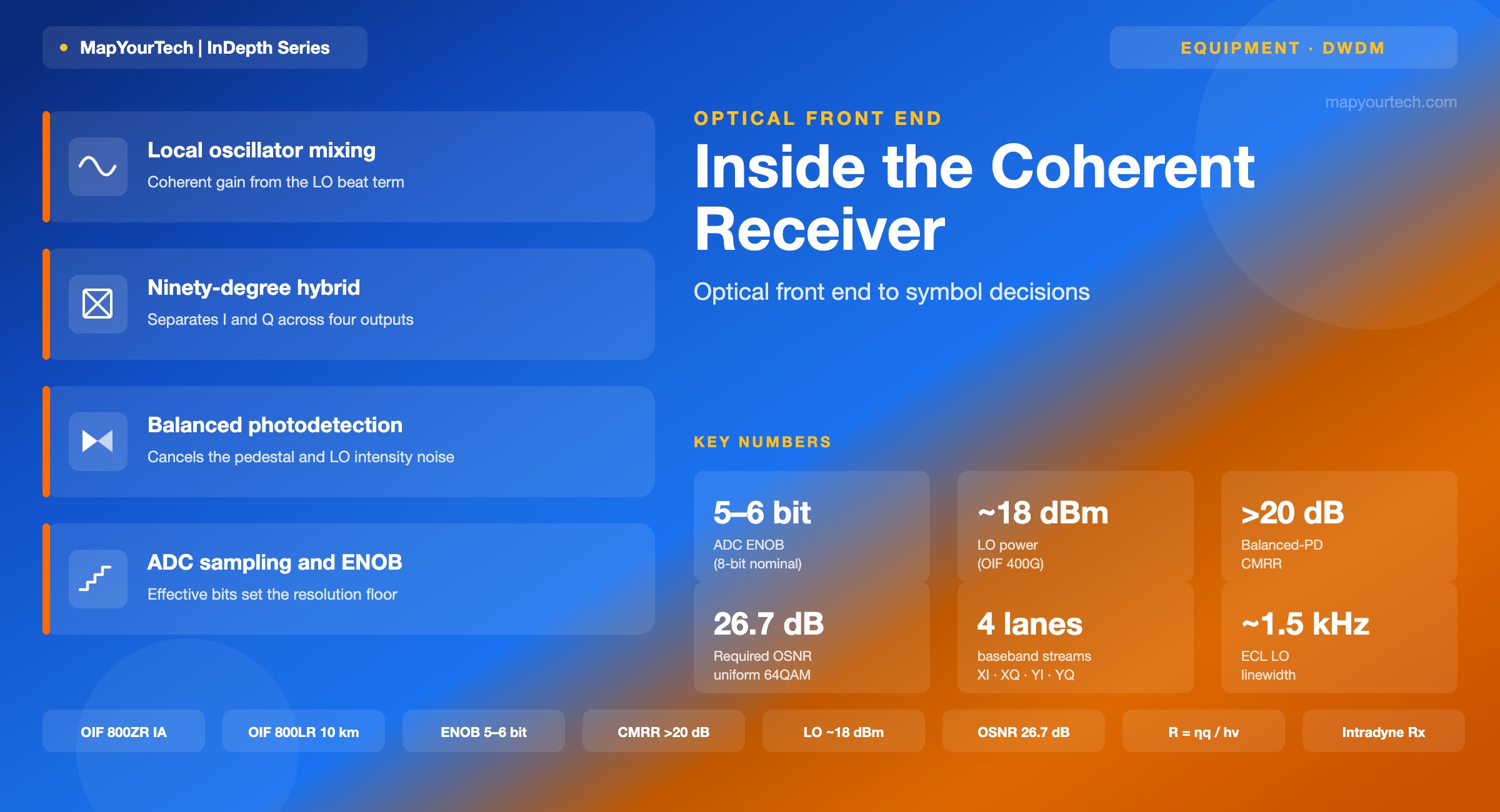
The receive path before the DSP gets credit — local oscillator mixing, the ninety-degree hybrid, balanced photodetection, transimpedance gain, and ADC sampling — with the impairment each stage adds and the boundary where it limits reach.

1. Introduction

A modern coherent line receiver hands its digital signal processor (DSP) four real-valued sample streams: the in-phase and quadrature components of the X polarization, and the in-phase and quadrature components of the Y polarization. Everything the DSP does afterward — chromatic dispersion compensation across thousands of picoseconds per nanometre, polarization demultiplexing, adaptive equalization, frequency-offset estimation, carrier-phase recovery, and soft-decision forward error correction — operates on those four streams and can never recover information the front end has already discarded. The front end is the part of the receiver that turns an optical field arriving on a fibre into those four numbers, and it is where the signal-to-noise ratio (SNR) that bounds the whole link is either preserved or quietly thrown away.

The chain is short and every stage is physical: a local oscillator (LO) laser, one or two polarization beam splitters (PBS), a pair of ninety-degree optical hybrids, four balanced photodetector pairs, four transimpedance amplifiers (TIAs), and four analog-to-digital converters (ADCs). Each element contributes gain, and each contributes a specific impairment. The LO supplies the mixing gain that lets a receiver detect a signal a thousand times weaker than the oscillator itself, and in the same act it stamps its own phase noise and frequency offset onto the output. The hybrid separates I from Q by imposing a ninety-degree phase relationship, and its deviation from exactly ninety degrees becomes IQ imbalance the DSP then has to unwind. Balanced detection cancels the large common-mode terms and the oscillator's intensity noise, but only as well as the two photodiodes match. The ADC sets the resolution ceiling through its effective number of bits (ENOB), which falls with input frequency and caps how much of the captured field survives quantization.

This article walks the receive path stage by stage in the order the light travels it. For each stage it states the mechanism, gives the governing expression with its variables named, quantifies a representative value with its evidence class, and names the boundary where the stage stops being ideal. The physics is stable — the coherent beat term and shot-noise floor were worked out in the 1980s — but the packaging is not: the same functional block that filled a shoebox of discrete optics in 2010 now sits inside a pluggable module drawing well under 30 watts. Where the numbers move, this piece uses verified 2026 figures and says where they came from. Readers who want the modulation-format context that sits above this layer will find it in the MapYourTech guide on QPSK and QAM constellation fundamentals, and the transceiver-selection view in the guide on coherent versus direct-detect transceivers.

2. The Receiver at a Glance: Four Lanes from Field to Bits

A dual-polarization coherent receiver is a phase-diverse and polarization-diverse structure. Phase diversity means it measures both the in-phase and quadrature projections of the optical field rather than intensity alone, so it recovers the full complex amplitude. Polarization diversity means it does this independently for the two orthogonal polarization states the transmitter used, because the fibre rotates and mixes those states unpredictably along the route and the DSP has to separate them afterward. The reference architecture is compact and has not changed in shape since commercial 100 Gb/s coherent shipped: one LO laser, two polarization beam splitters, two ninety-degree optical hybrids, four balanced photodiode pairs, and four ADCs feeding the DSP.

Dual-polarization coherent receiver front end block diagram Signal and local oscillator enter polarization beam splitters, feed two ninety-degree hybrids, then four balanced photodetectors, four transimpedance amplifiers, and four analog-to-digital converters feeding the DSP, forming the XI, XQ, YI and YQ lanes. Inputs Pol. split 90° hybrids Balanced PD TIA ADC Signal in DP-QAM field LO laser narrow linewidth PBS signal → X, Y LO split LO → X, Y 90° hybrid X polarization 4 outputs 90° hybrid Y polarization 4 outputs BPD · XI BPD · XQ BPD · YI BPD · YQ TIA TIA TIA TIA ADC ADC ADC ADC DSP Why four lanes Two polarizations × two quadratures = four real baseband streams. Each carries part of the complex field the transmitter launched. The DSP separates polarizations and unwinds channel impairments from these four numbers per symbol. Gain and loss per stage LO adds mixing gain (√P_LO). Hybrid + PD set quadrature accuracy and common-mode rejection. TIA adds voltage gain and input-referred noise. ADC sets resolution via ENOB and sampling rate. Nothing downstream recovers what these discard.
Figure 1: The dual-polarization coherent receive path. Signal and local oscillator each split into orthogonal polarizations, mix in two ninety-degree hybrids, and reach four balanced photodetector pairs whose outputs pass through transimpedance amplifiers and analog-to-digital converters to form the XI, XQ, YI and YQ lanes. Structure per the standard polarization-and-phase-diverse coherent receiver described in the coherent-detection literature.

Read left to right, the flow is straightforward. The incoming wavelength-division-multiplexed (WDM) signal, carrying dual-polarization quadrature-amplitude modulation (DP-QAM), enters a polarization beam splitter that resolves it into two orthogonal linear states, conventionally labelled X and Y. The LO laser passes through its own splitter so a copy reaches both branches. In each branch a ninety-degree hybrid mixes the signal state against the LO and produces four optical outputs whose relative phases are separated by ninety-degree steps. Those outputs land on two balanced photodetector pairs, one pair recovering the in-phase component and the other the quadrature component. Each balanced pair drives a transimpedance amplifier that converts its differential photocurrent into a voltage, which an ADC samples. Four ADCs, four streams, one DSP.

The value of doing all this — rather than detecting intensity with a single photodiode, as an intensity-modulation direct-detection (IM-DD) receiver does — is that coherent detection preserves the complete optical field: amplitude, phase, frequency, and polarization state all survive into the electrical domain. That is what makes two-dimensional formats such as DP-QPSK, DP-16QAM and DP-64QAM possible, and it is what lets the DSP undo chromatic and polarization-mode dispersion electronically instead of with inline optical compensators. The cost is the four-lane structure above and the linewidth-stable LO laser it depends on. The rest of this article is about what each of those blocks does well and where each one leaks performance.

Takeaway: The coherent front end exists to convert one optical field into four baseband numbers per symbol without losing the amplitude and phase the DSP needs. Every downstream algorithm is bounded by the SNR these four lanes deliver, so a front-end impairment is permanent in a way a DSP setting is not.

3. Where the Front End Came From

Coherent detection is not new; its eclipse and return explain why today's front end looks the way it does. Through the 1980s and early 1990s, coherent reception was an active research field precisely because the LO mixing gain gave a large sensitivity advantage over the direct-detection receivers of the day. A receiver that could beat a weak signal against a strong oscillator could pull usable data out of far less received power. Then the erbium-doped fibre amplifier (EDFA) arrived and offered on the order of 20 dB of optical gain without much difficulty, and a low-noise optical preamplifier in front of a simple direct-detection receiver improved sensitivity by 10 to 20 dB at a fraction of the complexity. In a cascaded long-haul link the reach is set by accumulated amplified-spontaneous-emission (ASE) noise, not by receiver shot noise, so the coherent sensitivity edge stopped mattering. Research into coherent systems faded for roughly a decade.

Three developments brought it back in the mid-2000s. High-speed digital electronics made it practical to sample the detected waveform and run complex demodulation in a DSP, which removed the need for an optical phase-locked loop to physically lock the LO to the incoming carrier — the hardest part of the old coherent receivers. The DSP could also compensate chromatic dispersion, polarization-mode dispersion, and component imperfections electronically, which direct detection could not. And the nested Mach-Zehnder IQ modulator made high-spectral-efficiency formats generatable at the transmitter. Shortly after 2000, self-coherent formats such as differential phase-shift keying appeared as a bridge; by the end of the decade, full digital coherent receivers at more than 100 Gb/s per wavelength had taken over the long-haul and metro markets.

What changed after that was integration, not architecture. Early digital coherent receivers were built from discrete optical components and bench instruments. The industry then defined the integrated coherent receiver (ICR) as a standardized module combining the hybrids, photodiodes, and often the TIAs in one package, and OIF implementation agreements pinned down its interfaces. Successive coherent modules moved the function into ever-smaller pluggable form factors: a C form-factor pluggable analog coherent optics (CFP2-ACO) variant kept the DSP on the host card; the CFP2 digital coherent optics (CFP2-DCO) variant pulled the DSP inside, one implementation integrating a tunable narrow-linewidth laser, a single silicon photonic chip carrying the quad ninety-degree hybrids with polarization diversity, the TIAs, the radio-frequency drivers, and a 16-nanometre-class CMOS DSP into a module rated near 20 watts for 200 Gb/s of 16QAM (vendor implementation). The functional block in Figure 1 stayed the same; the shoebox became a plug.

Takeaway: Coherent detection won not because it out-sensed direct detection — amplifiers erased that edge — but because pairing it with a DSP let one receiver undo dispersion and support high-order formats electronically. The front end's job has been constant since; only its packaging has collapsed from bench to pluggable.

4. Local Oscillator Mixing and Coherent Gain

The LO is a continuous-wave laser tuned to roughly the frequency of the channel being received. When its field adds to the incoming signal field at a photodiode, the photodiode responds to the square of the total field, and the cross term between the two — the beat — carries the signal's amplitude and phase. Write the two fields as a signal of instantaneous power Ps and phase φs, and an LO of average power PLO and phase φLO. Under ideal alignment the photocurrent is the sum of three parts.

Coherent photocurrent (single photodiode)

i(t) = R·[ Ps + PLO + 2√(PsPLO)·cos(Δωt + φs − φLO) ]

R = ηq/(hν) is the photodiode responsivity (A/W), with η the quantum efficiency, q the electron charge, h Planck's constant and ν the optical frequency. Δω is the angular frequency difference between LO and signal carriers. The sum-frequency term is removed by the photodiode's finite bandwidth. Result form per the standard coherent-detection treatment.

Two of the three terms are baggage. The Ps term is the direct-detection signal, tiny because the received power is low. The PLO term is a large direct-current pedestal. The useful part is the third term, the beat, whose amplitude is 2R√(PsPLO). Because the LO power sits under a square root and multiplies the signal, a strong LO amplifies the weak signal: this is coherent gain, sometimes called mixing gain. A signal a thousand times weaker than the LO still produces a beat term proportional to the geometric mean of the two powers, which is why coherent receivers reach sensitivities direct detection cannot. The same strong LO also raises the shot-noise floor, and the balance between mixing gain and shot noise is what sets the achievable SNR — covered in the noise-budget section.

Homodyne, heterodyne, and intradyne

The frequency difference Δω between the LO and the signal carrier decides the detection style. When it is zero and the LO phase tracks the signal, the beat falls to baseband: this is homodyne detection, and it historically demanded an optical phase-locked loop to hold the lock. When the difference is deliberately large — typically two to three times the signal bandwidth — the beat sits at an intermediate frequency (IF) in a passband and the receiver is heterodyne, recovering the signal with electrical processing at the IF. Modern digital coherent receivers use a third mode: intradyne. The LO runs free at approximately the signal frequency, with no phase lock, leaving a residual frequency offset that the DSP estimates and removes. Intradyne detection is why today's receivers need only a tunable narrow-linewidth LO and not a servo loop, and it is the mode every ZR-class pluggable uses.

Premium Article — Free 20% Preview

Read the Full Analysis with Premium

The remaining 80% of this article — the design numbers, trade-offs and field guidance — is part of MapYourTech Premium, along with the full premium library, courses and professional tools.

Instant access · Cancel anytime · 48-hour trial available
Sanjay Yadav

Optical Communications & Network Automation Expert | Author of 3 Books for Optical Engineers | Founder, MapYourTech

Optical networking engineer with nearly two decades of experience across DWDM, OTN, coherent optics, submarine systems, and cloud infrastructure. Founder of MapYourTech.

Follow on LinkedIn

You May Also Like

15 min read 19 0 Like Connector Types and Their Loss Budgets: SC, LC, MPO Skip to main content MapYourTech...
  • Free
  • July 11, 2026
16 min read 17 0 Like Cooled vs Uncooled Lasers: The Pluggable Power Trade-off Skip to main content MapYourTech |...
  • Free
  • July 11, 2026
16 min read 21 0 Like Automation Blast Radius: Scoping What a Bad Intent Can Touch Skip to main content...
  • Free
  • July 11, 2026

Course Title

Course description and key highlights

Course Content

Course Details


