
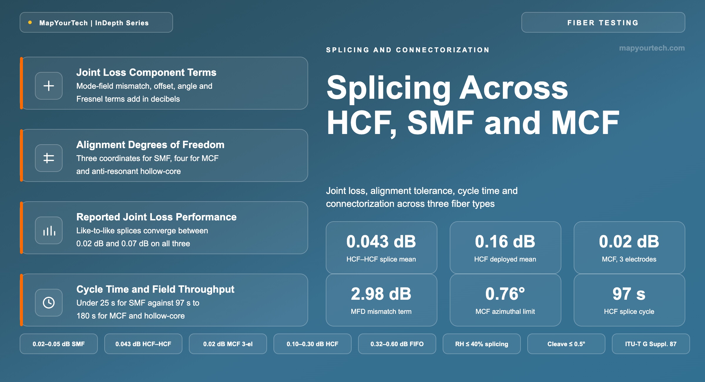
Splicing and Connectorization Across HCF, SMF and MCF
Joint loss, alignment degrees of freedom, cycle time, equipment and field practicality for standard single-mode, multi-core and hollow-core fiber terminations.
A splice loss is permanent; a connector loss is a maintenance decision.
1. Introduction
Every optical link ends at a joint, and every joint is where the fiber's advertised attenuation stops being the only number that governs the budget. A standard single-mode fiber joint asks the splicer to solve one geometric problem: bring two circular cores of nearly identical mode-field diameter onto a common axis. A multi-core fiber joint adds a rotational coordinate, because four or more cores sit off-axis and a rotation error converts directly into a lateral offset at each of them. A hollow-core fiber joint changes the problem again, because the guiding structure is a ring of thin glass capillaries surrounding air, and the arc that fuses two silica claddings will collapse that structure unless the energy is placed away from it.
These three problems now arrive on the same job site. Hollow-core fiber is in production service on hyperscaler routes, with deployments past 1,200 km and 15,000 km committed, and the mean splice loss reported from those deployments is 0.16 dB. Four-core multi-core fiber entered commercial submarine service on the Taiwan-Philippines-US system branches, the first commercial use of multi-core fiber in a subsea system, and in March 2026 a 192-core submarine cable system based on four-core fiber was announced together with its joint boxes and landing-station terminal racks. Standard G.652.D remains the medium into which both of them must terminate, because the transceivers, the patch panels and the test equipment all present a solid single-mode interface.
This article compares the three joint types on the four attributes that decide whether a technology reaches the field: the loss a joint contributes, the time a joint takes, the equipment a joint requires, and the environmental discipline a joint imposes. It works the loss physics from the coupling integral, derives the alignment tolerances each fiber type demands, and separates values that come from a standard, a measurement, a vendor statement or a theoretical bound. Splice-strength qualification, cable-jointing mechanics and connector polish geometry sit outside its scope.
Scope note: Throughout, joint loss values are stated per interface. A hollow-core span terminated at both ends into single-mode fiber therefore carries two transition losses, and a multi-core span terminated through fan-out devices carries two device insertion losses plus two fusion splices.
2. Joint Loss Definition and Component Terms
Joint loss is the optical power, expressed in decibels, that fails to transfer from the guided mode of one fiber into the guided mode of the next across a permanent or separable interface. It aggregates every mechanism at that interface: mismatch between the two mode fields, transverse and angular misalignment of their axes, reflection at any refractive-index step, and any power coupled into modes the receiving fiber does not guide to the far end.
2.1 Distinctions From Adjacent Quantities
Four quantities are routinely conflated at a fiber joint, and each has its own measurement and its own budget line.
Insertion loss against return loss. Insertion loss counts the power that does not continue forward; return loss counts the power sent backward toward the source. A flat silica-to-air interface reflects about 3.6% of incident power, which appears as 0.16 dB of insertion loss and a reflectance near −14.4 dB — the same event, reported on two different scales, and both belong in the acceptance record. The mechanisms that generate optical return loss and the connector geometries that control it apply unchanged at a hollow-core interface, with a far larger index step.
Read the Full Analysis with Premium
The remaining 88% of this article — the design numbers, trade-offs and field guidance — is part of MapYourTech Premium, along with the full premium library, courses and professional tools.
You May Also Like
-
Premium
-
August 27, 2026
-
Premium
-
August 27, 2026
-
Premium
-
August 27, 2026