
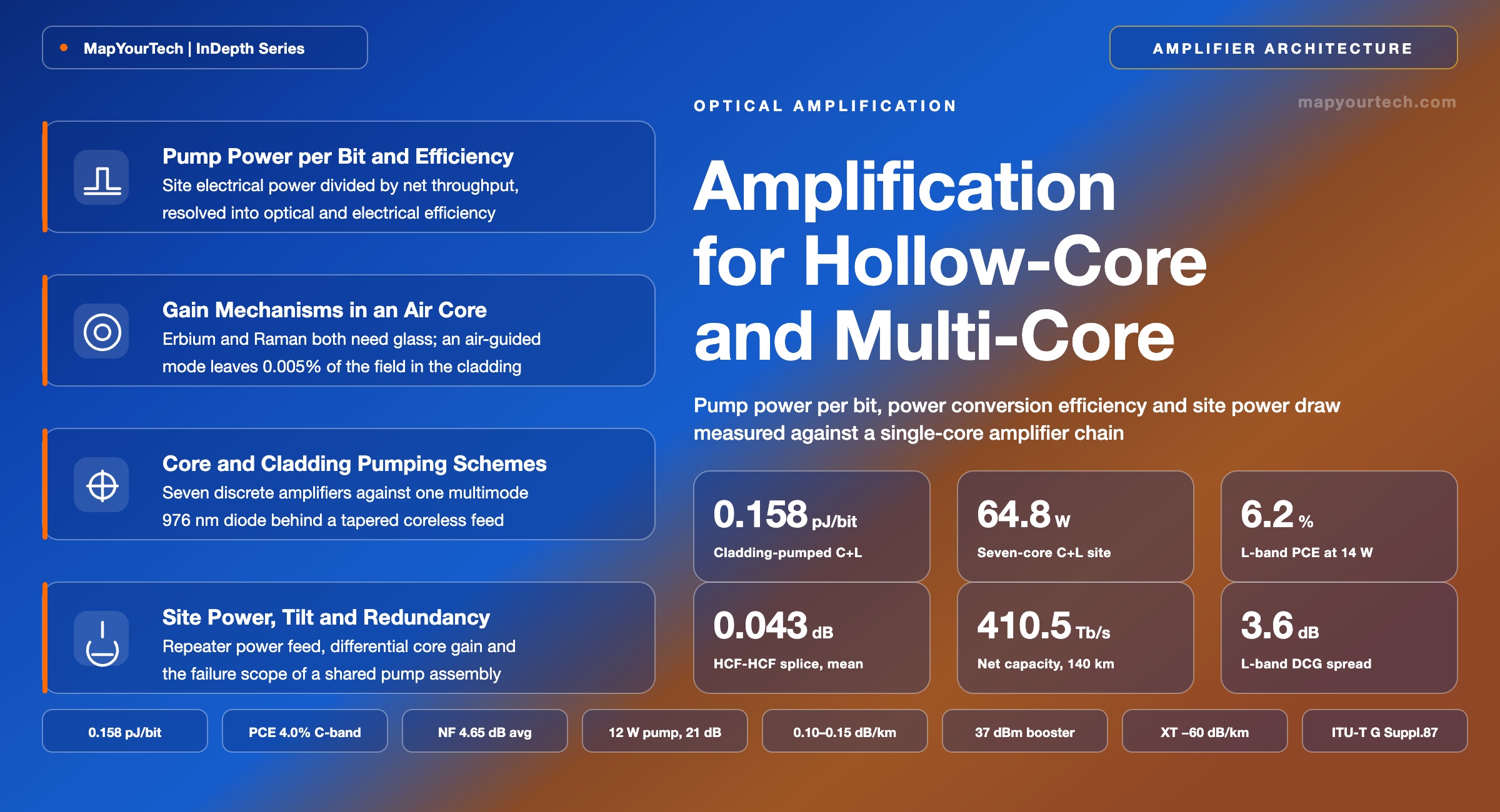
Amplification Architecture for Hollow-Core and Multi-Core
An air-guided core hosts no erbium and returns no useful Raman gain, and a multi-core fiber needs gain in every core at once — two fibers that break the amplifier assumptions built around single-core silica.
Distributed gain lowers the noise figure and adds a failure mode.
What You Will Learn
- Define pump power per bit in W/(Tb/s), convert it to pJ/bit, and resolve it into power conversion efficiency and pump-diode electrical efficiency (Section 2, Figure 1).
- Quantify why an air core returns no distributed gain, using a glass-field overlap near 5 × 10⁻⁵ and a nitrogen Raman shift of 69.9 THz against the 13.2 THz silica offset (Section 3).
- Build a hollow-core span around lumped high-power gain, from a 37 dBm booster carrying 25.6 Tb/s over 200.5 km to 400G reaching 726.1 km unrepeatered (Section 4, Figure 3).
- Select between core pumping and cladding pumping for a multi-core amplifier against pump-diode count, package volume and differential core gain (Section 5, Figure 4, Table 1).
- Anchor amplifier design to measured values: 12 W of C-band pump for gain above 18 dB, 14 W in the L-band for 6.2% conversion efficiency, and noise figure near 4.7 dB (Section 6, Figure 5).
- Convert a 64.8 W site draw and 410.5 Tb/s of net capacity into 0.158 pJ/bit, and compare it against the 0.237 pJ/bit of a seven-amplifier single-core array (Section 7, Figure 6).
- Place splices and transitions with a loss budget built from 0.08 dB hollow-core interconnection, 0.36 dB multi-core field splices and a sub-0.5 dB active-to-passive joint (Section 8).
- Diagnose an amplifier site on fibers that defeat conventional instruments, from weak hollow-core backscatter to differential core gain rising from 2 dB to 5 dB across the L-band (Sections 9 and 10).
1. Introduction
Erbium sits in glass, and the two fibers now entering deployment each remove part of what that requires. An anti-resonant hollow-core fiber (AR-HCF) carries better than 99.99% of its optical field in air, which removes the host that a dopant needs and removes the silica interaction length that distributed Raman amplification needs. A multi-core fiber (MCF) keeps the glass but multiplies the count of things to amplify: a seven-core fiber presents seven independent signal paths at every site, each of which has to arrive at the next span with the same gain, the same tilt and a comparable noise figure.
Both fibers are past the laboratory. Production hollow-core fiber now ships at 0.10–0.15 dB/km, a record 0.040 dB/km has been reported for a gap-tube assisted support-tube design, and the lowest published wideband figure is 0.091 dB/km at 1550 nm with under 0.2 dB/km across 66 THz (all measured values). Microsoft has more than 1,200 km of hollow-core fiber carrying live traffic with a stated plan above 12,000 km, and a seven-core submarine cable between two islands in the South China Sea has been characterized end to end with a matched multi-core erbium-doped fiber amplifier (MC-EDFA) in the path, delivering a net 410.5 Tb/s over 140 km (measured).
The amplifier is where the two fibers stop being drop-in replacements. A hollow-core span has no gain anywhere along its length, so the entire span loss is recovered at the endpoints by lumped amplifiers built on conventional erbium-doped fiber, and in exchange the fiber accepts a launch-power ceiling far above silica: 37 dBm boosters and 40 dBm single-channel launches appear in published results because the nonlinear coefficient is roughly three orders of magnitude below silica. A multi-core span has gain available everywhere a core runs, and the design question moves to how pump light reaches seven or nineteen cores at once without seven or nineteen pump assemblies, seven or nineteen wavelength combiners, and a repeater volume that no cable can carry.
This article compares those two amplification problems against a conventional single-core chain on three axes: architecture, pump power per bit, and site electrical draw. It covers the physics that removes distributed gain from an air core, the core-pumped and cladding-pumped multi-core architectures and the conditions that select each, the gain and noise relations with worked numbers, the design and commissioning practice around splices and transitions, the monitoring methods that survive on fibers hostile to conventional instruments, and the standards position as of 2026. Coherent transceiver design, fiber manufacture and cable mechanics stay outside its scope except where they set an amplifier constraint.
2. Pump Power per Bit and Power Conversion Efficiency
Pump power per bit is the electrical power an amplifier site draws divided by the net capacity that site carries, expressed in watts per terabit per second. It is the quantity that decides whether an amplifier architecture fits a submarine repeater power feed or a terrestrial hut breaker, and it is built from two efficiencies in series: the electrical-to-optical efficiency of the pump diode and the optical-to-optical power conversion efficiency of the gain medium.
2.1 The Three Efficiencies That Get Conflated
Power conversion efficiency against wall-plug efficiency. Power conversion efficiency (PCE) is optical output minus optical input, divided by launched pump power. It is a property of the gain fiber and the pumping geometry alone. Wall-plug or site efficiency includes the pump diode, the thermoelectric cooler where one is fitted, the control electronics and the monitoring photodiodes. A cladding-pumped multi-core amplifier measured at 6.2% PCE and a core-pumped single-core amplifier measured near 60% PCE can draw comparable electrical power per core, because a multimode 976 nm diode converts electricity to light far more efficiently than a single-mode 980 nm diode of the same optical output.
Power conversion efficiency against the quantum-defect ceiling. One pump photon can create at most one signal photon, so the ceiling on power conversion is the ratio of pump wavelength to signal wavelength: 976/1550 = 63.0% in the C-band and 976/1590 = 61.4% in the L-band (theoretical limits). Erbium-doped amplifiers pumped at 0.98 µm reach around 55–60% in practice against that 63% photon-energy ratio, while 1.48 µm pumping reaches 80–90% because its defect is smaller. Every architecture in this article is measured against that ceiling, not against 100%.
Read the Full Analysis with Premium
The remaining 88% of this article — the design numbers, trade-offs and field guidance — is part of MapYourTech Premium, along with the full premium library, courses and professional tools.
You May Also Like
-
Premium
-
August 27, 2026

-
Premium
-
August 27, 2026

-
Premium
-
August 27, 2026