
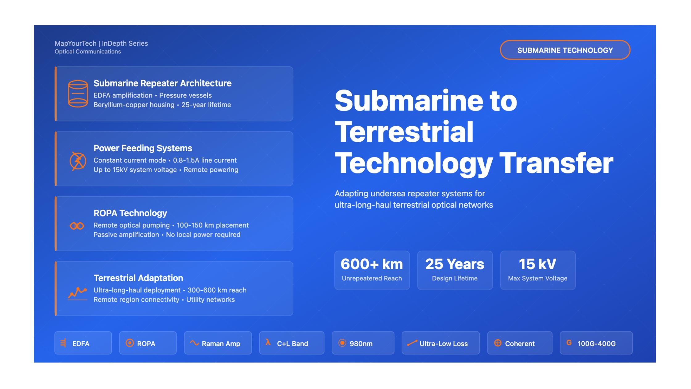

Bringing Undersea Repeater Technology to Terrestrial Applications: Challenges and Technological Aspects
A comprehensive technical exploration of adapting submarine optical amplification systems for ultra-long-haul terrestrial networks
Introduction
The optical telecommunications industry has witnessed remarkable technological evolution over the past several decades, with submarine and terrestrial networks following parallel yet distinct development trajectories. Submarine cable systems, designed to traverse vast oceanic distances exceeding 15,000 km, have pioneered numerous innovations in optical amplification, power management, and reliability engineering. These systems represent the pinnacle of telecommunications engineering, operating continuously for 25 years or more in environments where maintenance is extraordinarily difficult and costly.
In recent years, the boundaries between submarine and terrestrial optical networking technologies have begun to blur. As terrestrial networks face increasing demands for ultra-long-haul connectivity across challenging terrains such as deserts, tropical forests, tundra, and remote regions with limited infrastructure, the industry has started exploring the potential application of submarine repeater technologies to terrestrial deployments. This technology transfer represents more than simple equipment adaptation; it requires fundamental reconsideration of system architecture, environmental specifications, power delivery mechanisms, and operational paradigms.
The motivation for this technological convergence stems from multiple factors. Modern terrestrial networks increasingly require span lengths that exceed conventional 80-100 km repeater spacing, particularly in greenfield deployments across vast continental expanses. Traditional terrestrial repeater sites demand significant infrastructure investment including buildings, climate control systems, and reliable grid power connections. In contrast, submarine repeater technology offers the potential for passive, remotely powered amplification over extended distances with minimal infrastructure requirements at intermediate locations.
This article provides a comprehensive technical examination of the challenges, opportunities, and engineering considerations involved in adapting undersea repeater technology for terrestrial optical network applications. We explore the fundamental architectural differences between submarine and terrestrial systems, analyze the technical obstacles that must be overcome, and examine practical implementations where this technology transfer has already begun to occur. The discussion encompasses optical amplification principles, power feeding architectures, mechanical design considerations, reliability requirements, and system optimization strategies.
Historical Context and Evolution of Submarine Repeater Technology
Early Submarine Cable Systems
The history of submarine telecommunications systems extends back to the mid-19th century with the first successful transatlantic telegraph cable in 1866. These early systems utilized electrical repeaters to regenerate signals over long distances. The transition to optical fiber transmission in the 1980s revolutionized submarine communications, enabling dramatically higher capacities while reducing power consumption and improving reliability.
The first generation of optical submarine systems employed regenerative repeaters that performed optical-electrical-optical conversion, completely reconstructing the digital signal at each repeater location. These 3R systems (Reamplify, Reshape, Retime) required complex electronics and consumed significant electrical power. Operating at wavelengths around 1310 nm initially, and later at 1550 nm, these systems established the fundamental architecture of remotely powered submarine equipment deployed on the ocean floor.
The Optical Amplification Revolution
The development of Erbium-Doped Fiber Amplifiers in the late 1980s and early 1990s fundamentally transformed optical telecommunications. EDFAs provided all-optical amplification without requiring optical-electrical-optical conversion, dramatically simplifying repeater design while simultaneously enabling wavelength division multiplexing. The first commercial EDFA-based submarine system was deployed in 1995, marking a paradigm shift in undersea communications technology.
EDFA technology offered several critical advantages for submarine applications. The amplifiers exhibited broad optical bandwidth spanning 30-40 nm in the C-band, enabling tens to hundreds of wavelength channels to be amplified simultaneously. Power conversion efficiency improved significantly compared to regenerative repeaters, reducing the electrical power requirements for each amplification stage. Most importantly, the relative simplicity of EDFA architecture enhanced reliability, a paramount concern for equipment deployed thousands of meters underwater with a 25-year operational lifetime requirement.
Modern submarine EDFAs typically operate with the following characteristics: gain of 10-15 dB per amplifier stage, noise figure below 4.5 dB, output power ranging from 15-25 dBm per fiber pair, and support for 50-100 wavelength channels across C-band or C+L-band operation. These parameters represent careful optimization for submarine system requirements, balancing performance, power consumption, and reliability.
Power Feeding Architecture Development
A distinguishing characteristic of submarine repeater systems is their unique power delivery architecture. Unlike terrestrial repeaters that typically connect to local electrical grids, submarine repeaters receive electrical power through the same cable structure that carries the optical fibers. This requires specialized power feeding equipment at the terminal stations that can deliver constant current through the cable's copper conductor, with the return path through seawater and earth connections.
Submarine systems typically operate at line currents of 0.8-1.5 Amperes, with total system voltages potentially reaching 15,000 Volts for long transoceanic systems. The power feeding current is carefully controlled to provide stable operating conditions for the optical amplifiers while minimizing voltage requirements and ensuring safe operation throughout the system lifetime. Each repeater creates a voltage drop of 50-100 Volts, with the cumulative voltage increasing linearly with the number of repeaters in the system.
Mechanical Design Evolution
Submarine repeaters must withstand extraordinary environmental conditions, including hydrostatic pressures exceeding 103 MPa at maximum ocean depths, corrosive seawater exposure, and mechanical stresses during cable laying and recovery operations. The housing design has evolved to use high-performance materials such as beryllium-copper alloys, which offer exceptional strength-to-weight ratios, excellent thermal conductivity for passive cooling, and superior corrosion resistance.
Read the Full Analysis with Premium
The remaining 89% of this article — the design numbers, trade-offs and field guidance — is part of MapYourTech Premium, along with the full premium library, courses and professional tools.


