MapYourTech | MapYourBasics Series
ILA Site Constraints Shape Multi-Rail Line System Design
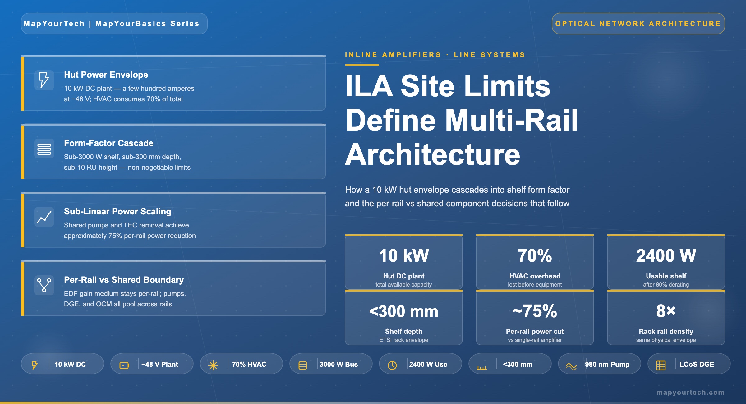
Terrestrial inline amplifier huts deliver only a few hundred amperes of DC power and burn up to 70% of it on cooling. Every multi-rail design choice — from uncooled pump sharing to LCoS gain equalization — traces back to a sub-3000 W shelf feed, a sub-300 mm shelf depth, and a sub-10 RU height envelope.
1. Introduction
The constraint that decides whether a multi-rail optical line system ships or stays on a slide deck is not photonic. It is the inline amplifier hut. ILA huts along North American terrestrial corridors were built decades ago along roadsides and railroad rights-of-way. They are physically small, fed by a few hundred amperes of −48 V DC, and cooled by HVAC that consumes a large fraction of every available watt before any optical equipment receives power. AI-driven scale-across has pushed required capacity per route from a single fully filled fiber pair to tens of fiber pairs lit in parallel, and the physical envelope of the ILA hut has not changed to accommodate it. Per-channel OSNR margin at the receiver still sets the upper bound on modulation order regardless of how many rails sit in parallel, but rail count now sets the upper bound on per-route capacity.
Three numbers sit at the boundary between what the hut allows and what the optical shelf must deliver. Shelf feeds must remain below 3000 W to fit power-distribution standards inherited from central-office practice. Shelf depth must remain below 300 mm to fit ILA hut racks that were never built to ETSI 600 mm or EIA 1000 mm depth. Shelf height for a high-rail-count line card must remain below 10 RU so that a single hut can host enough rails to justify a route upgrade. These numbers appear consistently in industry technical presentations on multi-rail system challenges and shape the public descriptions of multi-rail line system architectures across the optical equipment industry.
This article connects the three form-factor numbers to the physics they constrain. It examines why pump lasers dominate the EDFA power budget, why the gain medium is the only component that must remain replicated per rail, and why uncooled high-power 980 nm pumps and LCoS-based dynamic gain equalizers became the enabling technologies for sub-linear power scaling. It works through a per-rail vs shared-component matrix, presents the rail-count power scaling that current multi-rail systems claim, and identifies the correlated failure mode that pump sharing introduces. The reader will leave with a clear map between deployment-site physics and the component-level decisions that define a multi-rail amplifier line card.
2. The physical envelope of the terrestrial ILA hut
An ILA hut hosts in-line amplifier sites between fiber spans of roughly 80 km on a long-haul route. It contains no add-drop functionality, no transponders, no client-facing equipment — only the optical amplification and instrumentation needed to keep the wavelengths usable until they reach the next ROADM site. The hut is the smallest, simplest, and most replicated building block of a long-haul network, and its specification was set when a single fiber pair carrying ten 10 Gb/s wavelengths was the operational maximum.
2.1 What the hut actually delivers
A typical brownfield ILA hut along a North American long-haul route holds a handful of equipment racks and a couple hundred amperes of available DC power on the −48 V bus, sized for the original equipment plus modest expansion. Power-distribution standards published by Telcordia in GR-3160 and environmental qualification under GR-63-CORE define the operating envelope: temperature, humidity, vibration, EMI, fire safety, and the maximum dissipated power per rack that the cooling plant can remove. ETSI EN 300 019 covers comparable European deployments. These specifications are stable, not aspirational — equipment that violates them does not deploy, regardless of how attractive the photonic performance is.
2.2 Where the power actually goes
Cooling consumes up to 70% of available site power in older terrestrial huts, a figure widely cited in published descriptions of multi-rail line system architecture. The remaining 30% is the actual budget for optical and electronic equipment. A hut nominally rated at 10 kW of total DC capacity may therefore deliver only 3 kW for amplifier shelves once the HVAC plant is running at design conditions. This is the number the line-system designer must respect, not the rack-plate capacity.
The cooling overhead is structural, not accidental. ILA huts are typically uninsulated or lightly insulated metal enclosures sited in environments with wide ambient temperature swings. They use direct-expansion air conditioning rather than the chilled-water plants that data centers use. The thermal load is dominated by ambient gain through the building envelope plus the heat dissipated by every active component inside. Cutting that heat at the source — through component-level efficiency rather than larger HVAC — is the only path that does not require rebuilding the hut.
2.3 Why ETSI 600 mm and EIA 1000 mm depths do not help
Modern central offices and data centers accept rack depths of 600 mm to 1000 mm, allowing equipment shelves to extend deep into the rack with extensive cabling and cooling clearance. ILA huts predate this convention. Many use 300 mm-deep racks designed for legacy SDH and early DWDM equipment, with no path to expansion without removing walls. Multi-rail amplifier shelves must therefore design to the 300 mm depth limit even though every other deployment site allows more, because the hut population on any installed long-haul route is dominated by the legacy form factor.
Takeaway: An ILA hut is a fixed envelope of a few hundred DC amperes minus 70% cooling overhead, a small number of legacy-depth racks, and a thermal plant sized for 10 Gb/s-era equipment. Multi-rail system design starts from this envelope and works backwards to the shelf, the line card, and finally the components.
3. From site constraint to shelf constraint
The three shelf-level numbers — sub-3000 W, sub-300 mm, sub-10 RU — translate the hut envelope into specific equipment design rules. None of them is a vendor preference. Each one corresponds to a specific physical limit of the deployment site and propagates downward through the design.
3.1 Sub-3000 W shelf feed
Power distribution within a hut uses bus bars sized for the original equipment loads. The 3000 W ceiling per shelf reflects the maximum continuous draw that legacy −48 V circuit breakers, fuse panels, and bus bars can deliver to a single equipment slot without breaker derating. Pushing past 3000 W means re-running power infrastructure, which means truck rolls, planned outages, and capital expense per hut multiplied across hundreds or thousands of sites on a network. For an operator with 500 ILA sites on a transcontinental route, a shelf design that requires hut electrical upgrades is functionally non-deployable.
The 3000 W ceiling is a hard constraint at the shelf level, but the actual operating budget is lower. Headroom must remain for inrush current at startup, cooling fan power inside the shelf, and the power conversion losses between the −48 V input and the optical components. Steady-state power draw per shelf is typically planned at 80% of the rated maximum — about 2400 W of usable optical and electronic load.
3.2 Sub-300 mm depth and sub-10 RU height
Sub-300 mm depth is set by legacy rack frames in the hut. Sub-10 RU height is set by the requirement to host multiple shelves per rack while leaving cable management and airflow clearance. A single rack with 42 RU of usable height can host four shelves at 10 RU each plus 2 RU for power-distribution and fiber routing — or three shelves at 12 RU each, which forces the operator to either sacrifice a fourth shelf or run two ILA sites in parallel along the same route. Sub-10 RU is the threshold that keeps four shelves per rack achievable.
The sub-10 RU target also drives front-panel real estate. Each rail requires fiber connections for the in and out directions of both the amplifier and any monitoring port. A two-rail shelf needs four fiber connections; an eight-rail shelf needs sixteen. Front-panel density at sub-10 RU only works with high-density connectors and pre-terminated patch cords — an MPO-style approach borrowed from data-center practice — because individual LC connectors at this scale would consume the panel before all rails were terminated.
The cascade in Figure 2 explains why a single number — say, the sub-3000 W shelf feed — is not interesting in isolation. It becomes interesting when read alongside the cooling overhead, the rack depth, and the rail count target. Together, these numbers force the line-card architect to find power and space at the component level, because there is none at the system level.
4. Sub-linear power scaling at the component level
Inside a conventional inline EDFA, approximately 80% of the electrical power dissipates in pump-photon generation — pump laser drive current and any associated thermo-electric cooling. The remaining 20% covers control electronics, optical channel monitoring, dynamic gain equalization, OTDR and OSA functions, and small-signal handling. This ratio is broadly consistent across vendor implementations and follows directly from the wall-plug efficiency of available 980 nm and 14XX nm pump diodes. The architectural fundamentals — pump absorption, stimulated emission, and erbium population dynamics — are covered in detail in the MapYourTech treatment of basics of EDFA technology. For background on pump-source choices, see the comparison of 980 nm and 1480 nm pump-based EDFAs.
4.1 Why pump dominance forces the architecture
If pump generation drives 80% of EDFA power, then linearly replicating an EDFA per rail produces almost-linear total system power. A four-rail shelf would draw roughly four times the power of a single-rail shelf. With a 2400 W usable shelf budget and a 600 W single-rail draw, the operator gets four rails — and runs out of shelf-power budget before reaching the eight or sixteen rails per node that AI scale-across deployments require. Linear scaling does not fit the envelope.
The architecture that does fit shares the pump infrastructure across rails. A single uncooled high-power 980 nm pump diode delivers roughly 1 W to 1.4 W of optical power in industry-typical packages — enough to pump multiple parallel erbium-doped fiber gain media simultaneously through a fan-out coupler, provided the per-rail signal power and gain target sit within the saturation envelope of the shared pump. Multi-chip packages combining two pump dies in a single 10-pin or 3-pin housing further reduce footprint, replacing what would otherwise be two physical pump assemblies per rail with one assembly serving two or more rails.
4.2 Removing the TEC
Cooled pump diodes use a thermo-electric cooler (TEC) to hold the laser at a target case temperature, typically 25 °C, regardless of ambient. The TEC stabilizes wavelength and threshold current at the cost of significant electrical drive — a TEC pulling several watts of heat against a 50 °C ambient can dissipate as much electrical power as the pump diode itself. In a hut where cooling already consumes 70% of total power, every TEC is a double tax: it consumes electrical power directly, and it puts heat back into the air that the HVAC plant must remove again.
Modern uncooled high-power 980 nm pump diodes operate without a TEC. Wall-plug efficiency stays roughly flat across the 0–70 °C operating window, while cooled pumps see exponential power growth above 50 °C as the TEC works harder. The crossover point — beyond which uncooled wins by a wide margin — sits in the 40–50 °C ambient range, well within the operating envelope of older ILA huts during summer peaks. Removing TECs is therefore not a marginal optimization; it is the only path that keeps total dissipation flat across the operating temperature range that an actual hut sees.
Combining shared pumps, TEC removal, and pooled gain equalization, multi-rail systems achieve sub-linear total-power scaling against rail count. A four-rail card draws less than three times the power of a single-rail card, not four times. An eight-rail card draws less than five times. The shape of the curve — rather than any single point on it — is what makes the architecture deployable inside a fixed 2400 W shelf budget.
4.3 The rail-count power curve
The 32× density and 75% power-reduction figures publicly cited for current-generation multi-rail line systems are consistent with this curve shape, applied at the rail counts (8, 16, 32) those products target. These numbers are vendor marketing claims, not standardized benchmarks. Actual achievable density depends on the specific optical conditions of the deployment — span loss, modulation format, OSNR margin, and whether C-band only or C+L is in use.
5. The per-rail / shared-component boundary
Multi-rail architecture works because most of an EDFA's bill of materials can be shared, but not all of it. The boundary between shared and per-rail components is set by physics, not by cost or vendor preference. Light from one fiber pair cannot be amplified by a gain medium already amplifying light from a different fiber pair — they would interfere in the same erbium population. The gain medium therefore stays per-rail. Everything else — the energy that pumps that gain medium, the equalizer that flattens its output, the monitor that measures the result — is candidate for sharing.
5.1 What stays per-rail
The erbium-doped fiber itself must remain per-rail because it physically carries that rail's optical signals. The same applies to the input and output isolators that prevent backward-propagating ASE from corrupting the upstream span and to the variable optical attenuators on each rail's input that set per-channel power. These are the components that touch the rail's signal path directly. Their replication scales linearly with rail count, but their individual power draw is small — a few hundred milliwatts of control electronics per VOA, near zero for passive isolators and the EDF itself.
5.2 What can be shared
Pump lasers, dynamic gain equalizers, optical channel monitors, OTDR and OSA functions are all architecturally independent of which fiber pair they serve at any given instant. A pump diode delivers photons; the photons are routed through a coupler to whichever EDF needs them. A dynamic gain equalizer based on liquid crystal on silicon (LCoS) technology can be partitioned into multiple independent attenuation profiles within a single physical device. An OCM connected to a 16-port optical switch can sweep through every rail's input and output ports in turn, sampling each at sub-second intervals — fast enough for streaming telemetry but not requiring 16 separate spectrum analyzers.
| Component | Function | Replication | Why |
|---|---|---|---|
| Erbium-doped fiber | Active gain medium | Per rail | Physically carries the rail's signal; cannot be shared without routing the light |
| Input/output isolators | Reverse-light blocking | Per rail | Protects each rail's signal path from backward ASE |
| Variable optical attenuators | Per-rail input power control | Per rail | Sets independent operating point per fiber pair |
| 980 nm / 14XX nm pump diodes | Pump photon generation | Shared via dual/multi-chip packages | Photons are fungible across EDFs through fan-out couplers |
| Dynamic gain equalizer | Gain ripple flattening | Shared via LCoS array | One LCoS device implements multiple independent attenuation profiles |
| Optical channel monitor | Per-channel power measurement | Shared via fast optical switch | Sub-second sweep across rail ports meets streaming telemetry requirements |
| OTDR / OSA | Fault localization, spectrum analysis | Shared via switched metrology | Diagnostic functions tolerate sequential access across rails |
| Control / management plane | Telemetry, SDN northbound | Shared (single line card controller) | Software function, naturally pooled |
5.3 The correlated failure mode
Sharing introduces a failure mode that per-rail architectures do not have. A single pump laser failure degrades every rail sharing that device simultaneously. A single LCoS DGE failure removes gain equalization on all rails its array serves. Streaming telemetry can detect the failure in under a second, but the affected rails are all already off-spec at the moment of detection. This is a correlated failure — the kind that protection switching and reliability engineering treat differently from independent per-rail failures.
Vendor mitigations include redundant pump pairs with automatic switchover, dual-fed gain stages where two pump assemblies share the load, and software-driven graceful degradation that drops modulation order on affected channels rather than losing them entirely. Telecom MTBF targets — typically 10⁶ to 2×10⁵ hours per assembly, depending on operating temperature — must be met at the assembly level for the shared pumps because their failure has higher blast radius than a single-rail pump failure would. The architectural limit on rail count per shared pump pair is not technical; it is the risk an operator is willing to share across parallel paths.
6. Deployment patterns and architectural approaches
Multi-rail line systems entered commercial deployment between 2024 and 2026, driven primarily by hyperscaler demand for fiber capacity between AI training campuses. Two architectural patterns dominate the field and have been shown in live network trials.
6.1 The integrated multi-rail line card
The dominant architectural pattern places multiple rails on a single line card, with shared pumps, DGEs, and metrology pooled within the card boundary. Publicly described systems following this pattern cite up to 32× rail density improvement and 75% power reduction relative to single-rail predecessors, with rail counts of 8, 16, or 32 per card depending on the design point. Some implementations support C+L band operation on the same card to double per-fiber capacity. The integrated approach prioritizes density, automation, and fast turn-up of hundreds of fiber pairs at a single site — characteristics that align with scale-across DCI and long-haul AI campus interconnect requirements. These architectures fit within the broader picture of open line systems and multi-vendor coherent wavelengths.
6.1.1 Where the integrated approach wins
Greenfield deployments along new dark fiber routes — where the hut envelope can be designed around the line card rather than the other way around — favor the integrated multi-rail card. Rail count per chassis is high (16 to 32 typical), per-rail power is at the bottom of the curve, and the operator gets a single fault domain per fiber-pair group. The trade-off is the correlated failure mode: a single shared component takes multiple rails offline simultaneously.
6.1.2 Where the integrated approach struggles
Brownfield ILA huts with mixed equipment generations and tight site lease terms find integrated multi-rail cards harder to justify. The card's rail count may exceed the number of fiber pairs actually transiting that site. Stranded rails consume baseline power for shared infrastructure they do not amplify. A modular approach — smaller rail counts per shelf, multiple shelves per site — sometimes maps better to the actual fiber routing.
6.2 Brownfield retrofit constraints
Deploying a multi-rail card into an existing hut faces brownfield realities that greenfield AI campus deployments do not. The hut's HVAC plant was sized for the original equipment. Adding rails — even with 75% power reduction per rail — increases total dissipation if rail count grows faster than per-rail efficiency improves. An eight-rail card consuming 2 kW dissipates the same heat whether the per-rail efficiency was 75% better than legacy or not. The hut must accept the absolute thermal load, not the relative improvement.
Operators with hundreds of brownfield ILA sites typically stage deployment: validate the multi-rail card in selected huts that have headroom, monitor inlet/outlet temperatures over a full seasonal cycle, then scale across the route. The largest barrier is rarely the optical engineering. It is the operations process — confirming each hut individually, scheduling truck rolls for HVAC inspection, and renegotiating site lease terms where power draw exceeds the original specification.
6.3 Greenfield AI campus deployments
Greenfield AI scale-across deployments — new dark fiber routes between AI training campuses, often along power-corridor or pipeline rights-of-way — design huts from scratch for multi-rail equipment. These huts target lower cooling overhead (closer to 30–40% rather than 70%), higher per-rack power density (10 kW or more), and ETSI-compatible rack depths. The shelf-level form factor still drives the architecture, but the greenfield envelope provides more headroom — allowing higher rail counts per shelf and earlier introduction of C+L band operation without requiring custom hut designs at every site.
The architectural test for any multi-rail design is whether it deploys in a brownfield hut without civil works. A card that requires power upgrades, HVAC changes, or rack replacements is not solving the deployment problem — it is moving it from the photonics team to the operations team. The 32× density and 75% power-reduction claims become meaningful only when validated in the worst available hut on a route, not in a benchtop lab.
7. Future outlook
The constraint envelope of the ILA hut is not going to relax on the timescale of equipment refresh cycles. Building a new hut takes years; equipping an existing route with multi-rail systems takes months. The next round of architectural improvement therefore has to come from the same direction the current generation came from: more shared infrastructure per line card, higher pump efficiency at the same operating temperatures, and tighter integration of metrology functions.
Photonic integration is the most likely next step. Combining EDF gain stages, DGE elements, and OCM functions onto a single photonic integrated circuit per rail bank would reduce per-rail volume and per-rail power by another factor of two relative to the current discrete-component approach. Standards work in OIF and IEEE on disaggregated multi-rail line system interfaces is at an early stage but is converging on a common control plane that would let operators mix multi-rail line cards from multiple vendors on the same fiber route — extending the open line system model into the multi-rail era. Combination of multi-rail with C+L spectrum expansion, covered in the MapYourTech overview of C+L band DWDM systems, doubles per-fiber capacity on top of the rail-count multiplier.
The longer-term direction — once the brownfield ILA hut population has been refreshed — points toward cooling redesign at the hut level rather than further shaving at the shelf level. Reducing the 70% cooling overhead to 30–40%, comparable to modern data-center practice, would give every shelf in every hut a 2× power budget without any change at the optical line card. That investment sits on a different timescale and a different capital cycle than the line system itself, but it sets the upper bound on how far the current architecture can scale before something else has to change.
References
- Telcordia Technologies, GR-3160 — NEBS Requirements for Telecommunications Data Center Equipment and Spaces.
- Telcordia Technologies, GR-63-CORE — NEBS Requirements: Physical Protection.
- ETSI EN 300 019 — Environmental Engineering (EE); Environmental conditions and environmental tests for telecommunications equipment.
- ITU-T G.652 — Characteristics of a single-mode optical fibre and cable, ITU-T Study Group 15.
- ITU-T G.694.1 — Spectral grids for WDM applications: DWDM frequency grid, ITU-T Study Group 15.
- Ciena Insights, "What is hyper-rail or multi-rail?" — public blog post on multi-rail architecture, density and power claims.
- Cisco SP360 Blog, "Optical innovations deliver resilient, scalable, efficient AI networking" — public blog post on multi-rail open line system architecture.
- Coherent Corp., ECOC Market Focus presentation on multi-rail amplifier component design — public conference materials.
- P. Poggiolini et al., "The GN-model of fiber non-linear propagation and its applications," Journal of Lightwave Technology.
- E. Desurvire, "Erbium-Doped Fiber Amplifiers: Principles and Applications," Wiley-Interscience.
- OIF Implementation Agreement — Coherent Driver Modulator and Integrated Coherent Transmit-Receive Optical Sub-Assembly specifications, Optical Internetworking Forum.
Developed by MapYourTech Team
For educational purposes in Optical Networking Communications Technologies
Note: This guide is based on industry standards, best practices, and real-world implementation experiences. Specific implementations may vary based on equipment generation, network topology, and regulatory requirements. Always consult with qualified network engineers and follow current product documentation for actual deployments.
Feedback Welcome: If you have any suggestions, corrections, or improvements to propose, please feel free to write to us at [email protected]

Optical Communications & Network Automation Expert | Author of 3 Books for Optical Engineers | Founder, MapYourTech
Optical networking engineer with nearly two decades of experience across DWDM, OTN, coherent optics, submarine systems, and cloud infrastructure. Founder of MapYourTech. Read full bio →
Follow on LinkedInRelated Articles on MapYourTech