The Full-Spectrum Transponder: One Card, One Band
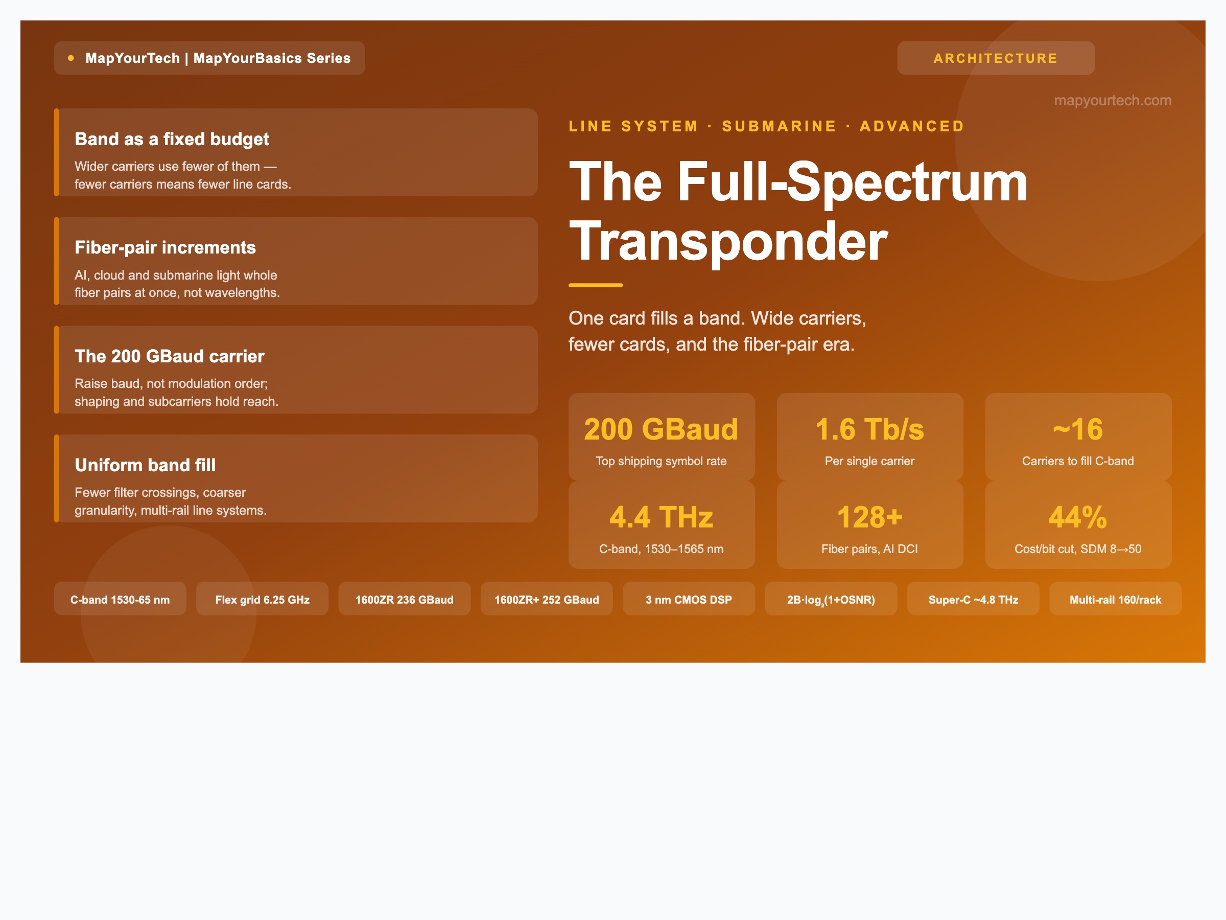
Very high baud coherent carriers are collapsing the number of line cards needed to fill a fiber pair. This is the mechanism behind the full-spectrum transponder, the fiber-pair-increment demand that pulls it into networks, and what uniform wide-carrier band fill does to line-system planning.
1. Introduction
For twenty years the unit of optical capacity was the wavelength, and the unit of hardware was the transponder that produced it: one card, one carrier, tens of cards to fill a fiber. That ratio is breaking. A single line card now generates a carrier wide enough that a handful of them fill an entire amplifier band, and vendors have begun packaging enough carriers onto one card to light a whole band, or a whole fiber pair, in a single slot. Nokia named this class the full-spectrum transponder (FST) at OFC 2026, describing a card that lights an entire band such as the C-band, or a full fiber pair, in one unit.
The shift is driven from two directions at once. On the demand side, hyperscale and AI operators no longer buy capacity a wavelength at a time; they light fiber pairs in full increments, so a card that fills a fiber in one step matches how the traffic actually arrives. On the technology side, coherent symbol rates have climbed from roughly 35 Gbaud a decade ago to 200 Gbaud in shipping products, and each doubling of baud roughly halves the number of carriers, and therefore cards, needed to fill a band.
This article works through the mechanism: how carrier width scales with baud rate, why fiber-pair-increment deployment favors filling a band from one card, what it takes to build a 200 Gbaud carrier, the choice between many pluggables and a multi-wavelength embedded engine, and the planning consequences of replacing a flexible grid of many carriers with a uniform fill of a few wide ones. Where a figure is a standard value, a lab measurement, a vendor claim, or a theoretical bound, that is stated alongside it.
2. What "full-spectrum" actually means
Start with the geometry. An amplifier band has a fixed usable width. The conventional C-band runs 1530–1565 nm, and the long-wavelength L-band runs 1565–1625 nm; both are standard-specified in ITU-T G.Sup39. The 35 nm of the C-band corresponds to about 4.4 THz of optical bandwidth (derived from the band edges), and commercial "Super-C" line systems stretch the usable window to roughly 6 THz by widening the amplifier and gain-flattening design. Whatever the exact edges, the band is a fixed budget of hertz that carriers must share.
A coherent carrier occupies a slot roughly equal to its symbol rate plus a guard band. At a root-raised-cosine roll-off of 0.1, the signal barely exceeds its baud in width, and practical channel spacing lands near 1.1 to 1.2 times the baud rate once laser uncertainty and cascaded filtering are accounted for. So a 35 Gbaud 100G carrier needs about 50 GHz, a 130 Gbaud 800G carrier about 150 GHz, and a 200 Gbaud 1.6T carrier about 250 to 300 GHz. Divide the band budget by the slot and you get the carrier count, which is also the card count in a one-carrier-per-card world.
Carriers to fill a band
Ncarriers ≈ Bband / ( Rs × (1 + ρeff) )
Bband = usable band width (Hz); Rs = symbol rate (Bd); ρeff = effective guard fraction (~0.1–0.25). At a fixed band budget, carrier count falls in inverse proportion to symbol rate. This is derived from the flexible-grid slot definition, not a vendor figure.
The consequence is direct and is the whole point of the full-spectrum transponder: raising the symbol rate does not just raise per-carrier capacity, it shrinks the number of carriers, and cards, needed to fill a fixed band. A band that took roughly ninety-six 50 GHz carriers in the 100G era takes on the order of sixteen 300 GHz carriers at 1.6T. Package those carriers together and one card fills the band.
Takeaway: A band is a fixed hertz budget. Wider carriers mean fewer carriers, and in a one-carrier-per-card world that means fewer cards. The full-spectrum transponder finishes the logic by putting enough wide carriers on one card to fill the band.
3. Why now: capacity arrives in fiber-pair increments
Filling a whole band from one card only pays off if the demand actually arrives in band-sized quanta. For gradual metro growth it does not, and the flexibility of a fine grid is worth more than the card savings. The full-spectrum transponder exists because a large and growing class of demand now arrives in exactly those quanta: hyperscale and AI data-center interconnect.
The numbers make the shift concrete. At OFC 2026 Meta stated that regional data-center interconnect typically needs 16 to 48 fiber pairs or more, while AI-driven regional interconnect needs 128 or more fiber pairs (operator statement). When an operator commissions capacity that large, it lights fiber pairs whole rather than channel by channel, and a card that fills a fiber pair in one step is a natural fit. The same economics has been visible in submarine systems for years, where the entire cable is designed once and the cost of the wet plant dominates.
The submarine precedent: dilute the power, fill the fiber
Submarine systems are supply-power constrained, because the direct current that feeds the submerged repeaters is delivered from the two cable ends. That constraint reshaped the design philosophy toward space-division multiplexing (SDM): rather than push every fiber pair to its nonlinear limit, spread the available electrical power across many parallel fiber pairs and run each one gently. The techno-economic result from the SDM literature is striking — evolving from an 8-fiber-pair system to a roughly 50-fiber-pair system yields on the order of 44% cost-per-bit savings, and the cost-optimum system operates in the linear propagation regime rather than the nonlinearity-limited one (modeled result, SDM techno-economic literature).
Two counter-intuitive consequences follow, and both matter for the full-spectrum transponder. First, at the cost optimum a fiber pair carries a modest capacity, so it can be filled by a small number of carriers rather than a densely packed grid. Second, the same analysis finds that narrower-band systems can be preferred, because gain-flattening filters lose optical power in proportion to the width they flatten, so a card that fills a modest band cleanly is well matched to a low-power-per-fiber SDM design.
Practical Example — sizing carriers to a fiber pair
Take a submarine SDM fiber pair budgeted for roughly 20 Tb/s at the cost-optimum operating point. With 200 Gbaud carriers at about 1.2 Tb/s each on that route's OSNR, filling the pair takes on the order of seventeen carriers — comfortably a single full-spectrum transponder rather than seventeen separate cards. The same card, run at a shorter reach where 1.6 Tb/s per carrier holds, fills the pair with about a dozen carriers. The planning question shifts from "how many transponders per fiber" to "how many fibers per card." Capacity figures here are illustrative and depend on route OSNR.
The reason low power per fiber helps is that fiber nonlinearity grows with launch power. Spreading a fixed power budget across many fibers pushes each below the nonlinear knee, so the link becomes noise-limited and linear. In that regime large-effective-area fiber and digital nonlinearity compensation stop paying for themselves — a result that inverts a decade of single-fiber design intuition.
4. Building the wide carrier: 200 GBaud and beyond
The full-spectrum transponder rests on one hard-won capability: generating and receiving a carrier at 200 Gbaud and above without giving back the reach that makes it useful. Ciena's WaveLogic 6 Extreme is the shipping reference point, described as a multi-rate, single-carrier coherent engine delivering up to 1.6 Tb/s on a single wavelength at 200 Gbaud, built on a 3 nm CMOS digital signal processor and operating across both C- and L-band, with up to eight frequency-division subcarriers (vendor specifications). Nokia's PSE-6s and ICE7 super-coherent engines reach 130 to 140 Gbaud for up to 1.2 Tb/s per wavelength on 5 nm DSPs (vendor specifications). The industry names the class by baud: engines above 120 Gbaud are "Gen120," and Ciena's 200 Gbaud design is "Gen200" (market-research taxonomy, publicly released).
Why raise baud rather than modulation order
Capacity per carrier can grow two ways: more bits per symbol, or more symbols per second. The two are not equivalent for reach. Higher-order modulation packs bits tightly but needs more optical signal-to-noise ratio, so it shortens reach; raising baud keeps the modulation order low and stays tolerant of noise. The information-theoretic reason is that capacity scales linearly with bandwidth but only logarithmically with signal-to-noise ratio.
Capacity: bandwidth is cheap, OSNR is dear
C = ∑i 2 Bi · log2( 1 + OSNRi )
C = capacity; Bi = per-carrier bandwidth; OSNRi = per-carrier signal-to-noise ratio; factor 2 for dual polarization. Doubling B doubles capacity; doubling OSNR adds one bit. This is why widening carriers, not stacking constellation points, is the path to filling a band at reach. Theoretical limit, from the Gaussian-noise capacity literature.
Two techniques let the wide carrier keep its reach. Probabilistic constellation shaping transmits inner constellation points more often than outer ones, buying up to 1.53 dB of sensitivity over uniform QAM at the asymptotic limit (theoretical bound) and letting the engine dial bits-per-symbol in fine steps to fit the reach. Digital subcarriers split one wide carrier into several lower-baud tributaries inside the DSP, which reduces sensitivity to chromatic dispersion and equalization-enhanced phase noise; the OIF 1600ZR+ baseline uses two digital subcarriers for exactly this reason (standard-specified).
The electro-optics wall
Pushing past 200 Gbaud is an analog problem before it is a digital one. Silicon-photonic modulators run short of bandwidth at these symbol rates, so the industry is moving to indium phosphide and thin-film lithium niobate modulators for the higher electrical bandwidth and lower drive voltage they offer (industry, trade press). The driver and trans-impedance amplifiers, and the radio-frequency interconnect between the DSP and the analog front end, all have to carry very wide bandwidth with tightly managed crosstalk, skew, and reflection. This is why the standards path to 1600G, discussed next, hinges on baud-rate feasibility as much as on DSP node.
| Engine | Top symbol rate | Per-carrier capacity | DSP node | Bands |
|---|---|---|---|---|
| Ciena WaveLogic 6 Extreme | 200 GBaud | Up to 1.6 Tb/s | 3 nm CMOS | C and L |
| Nokia ICE7 | 140 GBaud | Up to 1.2 Tb/s | 5 nm CMOS | C and L |
| Nokia PSE-6s | 130 GBaud+ | Up to 1.2 Tb/s | 5 nm CMOS | C and L |
| Nokia ICE6 | ~90–100 GBaud | Up to 0.8 Tb/s/carrier | 7 nm CMOS | C and L |
The standard track: OIF 1600G
Embedded engines lead, and the pluggable ecosystem follows through the OIF. Three 1600 Gb/s interfaces are in definition, and their parameters are now firm enough to plan against. The status below is as of 2026 and should be re-checked against the OIF's published implementation agreements as they issue.
| Interface | Symbol rate | Modulation / FEC | Target reach | Target power | IA status |
|---|---|---|---|---|---|
| 1600ZR | ~236 GBaud | Single-carrier DP-16QAM, OFEC | 80–120 km | ~32–35 W | Baseline Q3 2025; IA due Q2 2026 |
| 1600ZR+ | 252 GBaud | DP-16QAM + PCS, dual subcarrier, OFEC | Up to ~1,000 km | ~38–40 W | Baseline Q4 2025; IA scheduled Q3 2026 |
| 1600CL | Under study | Coherent-lite, LR focus | Campus / intra-DC | Optimized | Earlier stage; may scale toward 3.2T |
The direction of travel is explicit in the OIF's own framing: 1600ZR is a single-carrier, single-lambda 16QAM interface aimed at data-center interconnect out to about 120 km, while the OIF has publicly noted the path continues toward higher baud solutions approaching 300 Gbaud (standard status). In parallel, IEEE 802.3dj is defining 1.6-terabit Ethernet interfaces anticipated in the second half of 2026 (standard status).
Takeaway: The wide carrier is built by raising baud, not constellation order, then protecting reach with shaping and digital subcarriers. Above 200 Gbaud the limiter is analog bandwidth, which is steering modulators toward indium phosphide and thin-film lithium niobate.
5. Two roads to a full band on one card
Given a wide carrier, there are two ways to put a whole band's worth of them on a single card, and the choice was an open question at OFC 2026 rather than a settled answer.
Road one: an array of pluggable coherent modules
The first road packs many independent coherent pluggables onto one card — each a complete DSP-plus-optics module producing one carrier, with the carriers combined by an on-card multiplexer. Nokia's illustration of a full-spectrum transponder was a card supporting 32 × 300 GHz 1.6T interfaces (vendor illustration). Doing the arithmetic transparently: 32 carriers at 1.6 Tb/s is 51.2 Tb/s of aggregate line-side capacity, and 32 slots at 300 GHz occupy 9.6 THz — roughly a full C+L fiber pair rather than a single band (derived from the vendor figures). Scaled to the C-band alone, the same 300 GHz slot gives about sixteen carriers.
This road inherits the pluggable ecosystem's interoperability and supply diversity, and it lets a card mix rates per carrier. Its cost is power density and thermal management: dozens of 40-watt-class modules in one slot is a serious cooling problem, and it is why the OIF power targets in Table 2 matter so much.
Road two: a multi-wavelength embedded engine
The second road generates many carriers from shared photonics rather than replicating whole modules — a comb laser or highly integrated multi-wavelength photonic integrated circuit feeding a multi-wavelength DSP. Sharing the light source and the integration substrate across carriers can cut cost and power below an array of discrete modules, at the price of losing the pluggable model's modular swap and multi-vendor sourcing. Which road wins is unresolved, and the answer may differ by application: pluggable arrays where interoperability rules, embedded multi-wavelength engines where density and power dominate.
A related building block appeared alongside the full-spectrum transponder: media converters that integrate intensity-modulated direct-detect client optics with coherent line optics in a single package. These bridge co-packaged-optics switches to coherent line transmission for scale-across between sites, and they let the client and line sides evolve on their own technology curves inside one card.
Practical Example — where the power budget bites
Consider filling a C-band with 1.6T carriers on the pluggable road at roughly the OIF 1600ZR+ target of 38 to 40 watts per module (standard-specified target). Sixteen carriers is on the order of 620 to 640 watts of pluggable optics in a single card, before the host, DSP overhead, and cooling. That figure is what pushes designers toward shared-source multi-wavelength engines for the densest full-band applications, and toward lower-power 1600ZR modes where reach permits. Per-module power is a target figure and will settle as implementation agreements finalize.
6. What it does to line-system planning
Replacing a fine grid of many carriers with a uniform fill of a few wide ones changes the line system as much as the transponder shelf. The effects cut both ways.
Fewer filter crossings, coarser granularity
Fewer, wider carriers mean fewer wavelength-selective-switch crossings to plan and fewer objects for the control plane to route, which simplifies spectral assignment. The trade is granularity. A 300 GHz carrier cannot be subdivided, so restoration and grooming happen in 1.6 Tb/s quanta; a partial failure or a partial spectrum gap cannot be filled by half a carrier. The flexible grid that ITU-T G.694.1 defines at 6.25 GHz central-frequency and 12.5 GHz slot-width granularity (standard-specified) still governs where carriers sit, but a band filled uniformly with wide carriers uses little of that fine granularity. Planning shifts from packing a flexible mosaic toward laying down a fixed, uniform comb.
Band edges and gain flattening
A uniform wide-carrier fill puts carriers hard against the band edges, where amplifier gain roll-off and gain-flattening-filter error are worst. Gain-flattening filters also cost optical power in proportion to the width they equalize: excess loss rises sharply for equalization bandwidths beyond about 38 nm, and the widest EDFA windows deployed in undersea systems sit near 41 nm (measured, undersea transmission literature). This is the same physics that favors modest per-fiber bands in SDM designs, and it means an FST filling a wide band still has to hold the edge carriers within the amplifier's usable, well-flattened window.
Multi-rail line systems
If demand arrives in fiber-pair increments, the amplifier line has to scale in fiber-pair increments too. The line-system answer at OFC 2026 was the multi-rail in-line amplifier: a single roughly 1RU card providing bidirectional amplification for several fiber pairs at once, sharing optical time-domain reflectometry, optical channel monitoring, and digital gain equalization, and using low-power uncooled or multi-chip pump lasers. Nokia described a multi-rail solution supporting up to 160 C+L in-line amplifiers per rack (vendor claim). The mechanism that saves power — sharing one pump and one monitoring chain across several rails — also creates a correlated failure mode: a shared pump or gain-equalizer fault degrades every rail it serves at once, which per-fiber amplifiers do not do. That trade belongs in the availability model, not just the power budget.
Wide-carrier uniformity and shared line-system hardware both concentrate risk. A single 1.6T carrier is an indivisible failure unit; a shared multi-rail pump ties several fiber pairs to one component. The full-spectrum model trades granular resilience for density and power, so restoration design has to compensate deliberately — through fiber-pair-level diversity and spare capacity rather than sub-carrier grooming.
The control plane picks up the flexibility
What the fixed comb gives up in spectral agility, the control plane gives back in the electrical domain. Modern engines tune baud rate, modulation, shaping, and FEC continuously, so an operator can trade capacity for reach per carrier as conditions change. Nokia's elastic photonic networking, entering networks in mid-2026 (vendor), has the control plane adjust shaping bits-per-symbol or reduce baud to fit available spectrum after a failure, establishing a lower-rate wavelength on a path that can no longer carry the full rate. The flexibility moves from the grid to the modem.
| Planning dimension | Full-spectrum wide-carrier fill | Fine flexible grid |
|---|---|---|
| Cards to fill a band | Few (one card can fill a band) | Many, one per carrier |
| Spectral granularity | Coarse (~300 GHz quanta) | Fine (down to 12.5 GHz slots) |
| Restoration unit | Whole 1.6T carrier | Sub-band, per wavelength |
| Filter crossings to plan | Fewer | More |
| Band-edge exposure | Higher (edge carriers) | Lower (edges can stay empty) |
| Best fit | Fiber-pair-increment demand (AI, cloud, submarine) | Incremental metro and mesh growth |
Takeaway: Uniform wide-carrier fill simplifies spectral planning and cuts card and amplifier count, but it coarsens restoration granularity and concentrates failure. It fits fiber-pair-increment demand well and gradual mesh growth poorly, with the control plane restoring flexibility in the electrical domain.
7. Design guidelines
A few practical rules follow from the mechanism, for engineers weighing a full-spectrum approach against a conventional transponder shelf.
- Match the card to how demand arrives. Full-band fill pays when capacity is commissioned in fiber-pair increments — AI and cloud interconnect, submarine, large data-center interconnect. For incremental metro or mesh growth, a finer grid and per-wavelength cards keep more options open.
- Size carriers to the route's OSNR, not the datasheet peak. A 1.6 Tb/s carrier holds over metro and short regional reach; longer routes settle at 1.2 Tb/s or below on the same engine. Plan the carrier count from the achievable per-carrier rate on the specific path, using C+L capacity-reach references as a starting point.
- Keep edge carriers inside the flattened window. Uniform fill exposes band-edge carriers to gain roll-off and gain-flattening-filter error. Verify the amplifier's usable, well-equalized width covers every carrier, and leave margin at the edges rather than pushing the last carrier into the roll-off.
- Model shared-hardware failure explicitly. Multi-rail amplifiers and indivisible wide carriers concentrate risk. Build fiber-pair diversity and spare capacity into the restoration plan, and confirm the availability target still holds with correlated pump and gain-equalizer faults.
- Let the modem carry the flexibility. With continuous baud, shaping, and FEC control, plan for the control plane to trade rate for reach per carrier. An elastic scheme can hold service through impairments that would strand a fixed-rate carrier.
- Watch the power envelope on pluggable arrays. Filling a band with many 1600ZR-class pluggables is a cooling problem before it is a capacity problem. Where density dominates, weigh a shared-source multi-wavelength engine; where interoperability dominates, weigh the pluggable array.
8. Summary
The full-spectrum transponder is the endpoint of a simple scaling law: a band is a fixed budget of hertz, wider carriers use fewer of them, and enough wide carriers on one card fill the band. Three forces bring it into networks now — 200 Gbaud electro-optics that make the wide carrier real, an OIF 1600G standards track pulling it into pluggables, and hyperscale, AI, and submarine demand that arrives in fiber-pair increments rather than single wavelengths. The engineering cost is granularity: uniform wide-carrier fill and shared multi-rail line hardware trade sub-carrier flexibility and independent failure for density and power, with the control plane restoring flexibility in the electrical domain.
Quick reference. C-band 1530–1565 nm (~4.4 THz), L-band 1565–1625 nm (standard-specified). Flexible grid 6.25 GHz central-frequency, 12.5 GHz slot-width granularity (standard-specified). Shipping top baud 200 GBaud at up to 1.6 Tb/s per carrier (vendor). OIF 1600ZR ~236 GBaud / ~32–35 W, 1600ZR+ 252 GBaud / ~38–40 W (standard-specified targets). To go deeper, the MapYourTech guides on baud rate, bit rate and spectral width and on channel monitoring across the band cover the underlying measurements a full-spectrum design has to hold.
References
- ITU-T G.Sup39 — Optical System Design and Engineering Considerations, ITU-T Study Group 15.
- ITU-T G.694.1 — Spectral Grids for WDM Applications: DWDM Frequency Grid, ITU-T Study Group 15.
- Optical Internetworking Forum — 1600ZR and 1600ZR+ Coherent Line Interface Projects, OIF Physical and Link Layer Working Group.
- IEEE 802.3dj — 1.6 Tb/s Ethernet Task Force, IEEE 802.3 Ethernet Working Group.
- Sanjay Yadav, "Optical Network Communications: An Engineer's Perspective" — Bridge the Gap Between Theory and Practice in Optical Networking.

Optical Communications & Network Automation Expert | Author of 3 Books for Optical Engineers | Founder, MapYourTech
Optical networking engineer with nearly two decades of experience across DWDM, OTN, coherent optics, submarine systems, and cloud infrastructure. Founder of MapYourTech. Read full bio →
Follow on LinkedInRelated Articles on MapYourTech