
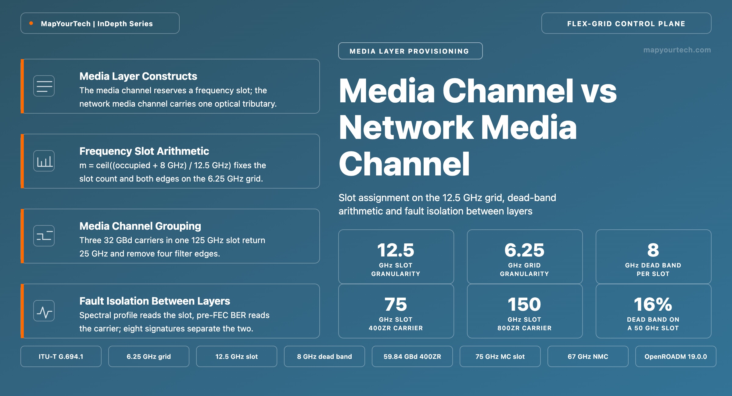
Media Channel vs Network Media Channel Provisioning in Flex-Grid
The ITU-T media constructs that flexible-grid provisioning writes, with worked slot assignments on the 12.5 GHz grid and the controller-level rules that follow from the distinction.
The best network design is one that anticipates tomorrow’s needs.
What You Will Learn
- Define the media channel and the network media channel in the terms ITU-T G.807 uses, and place each against the optical tributary signal it carries.
- Locate both objects in the ROADM interface hierarchy, from the OTS interface through the media channel trail termination point to the cross-connect endpoint.
- Compute a frequency slot from a carrier symbol rate using m = ceil((occupied bandwidth + 8 GHz) / 12.5 GHz), checked against the 400ZR case at 59.84 GBd.
- Quantify the fixed 8 GHz dead-band overhead, which consumes 16% of a 50 GHz slot and 3% of a 275 GHz slot.
- Construct a grouped media channel carrying three 32 GBd carriers in 125 GHz rather than 150 GHz, recovering 25 GHz and four filter edges.
- Select between grouped and separate media channels using filter-edge count against the independent-restoration constraint.
- Convert a power spectral density target in dBm/12.5 GHz into per-network-media-channel launch power at any slot width.
- Isolate a fault to the media channel layer or the carrier layer using eight tabulated provisioning and transmission signatures.
1. Introduction
A media channel reserves a frequency slot through the optical media; a network media channel carries exactly one optical tributary signal inside that reservation. ITU-T G.807 defines both as media associations, and the difference decides which object a controller writes when a wavelength is turned up, which object a cross-connect terminates on, and which object a wavelength selective switch filter shape follows.
The two constructs are routinely treated as one because for fifteen years they behaved as one. Under the fixed 50 GHz grid an optical channel was simultaneously the spectrum reservation, the carrier, and the switching object, so a single OCh interface carried all three meanings. The flexible grid separated them. Once a slot can be 37.5 GHz or 275 GHz wide and can hold one carrier or five, the reservation and the carrier stop being the same object, and the data models that operators write against (OpenROADM, the ONF Transport API, vendor NETCONF trees) expose them separately. An engineer who reads media channel and thinks wavelength will mis-size slots, mis-place guard bands, and mis-diagnose faults.
The distinction has direct operational consequences. Dead bands sit at media channel edges and nowhere else, so two carriers inside one media channel abut with no separation while the same two carriers in adjacent media channels are separated by 8 GHz of unusable spectrum. Cross-connections are made between network media channel endpoints, so routing granularity is per carrier while spectrum reservation granularity is per slot. A spectrum service sold to a third party is a media channel with no network media channels visible to the line-system operator at all. Each of these is a design decision that a controller or a planning tool has to get right before the first transponder is tuned.
This article works through the constructs as the standards define them, then through the object model as a ROADM data plane exposes it, then through the slot arithmetic with values computed for 32 GBd, 59.84 GBd, 118.2 GBd and 240 GBd carriers. It closes with grouping trade-offs, a provisioning sequence, per-channel power conversion, a fault-isolation reference and a model comparison. Readers new to the underlying grid definitions may want the companion treatment of the ITU-T G.694.1 fixed and flexible grids alongside this one.
Takeaway: The media channel is a spectrum reservation that shapes filters and exists with no carrier present; the network media channel is a carrier object that terminates cross-connects and exists only where an optical tributary signal is placed. Every provisioning, guard-band and fault-isolation decision in a flexible-grid network follows from keeping those two apart.
2. Media Layer Constructs in ITU-T G.807 and G.872
ITU-T G.807, approved in February 2020 with Amendment 1 in January 2021, is the standard that defines the optical media network as a layer in its own right, separate from the digital layers that ride on it. It supplies the construct set: media channels, media channel groups, media elements and the monitoring points attached to them. ITU-T G.872, whose current edition is dated March 2024, then describes how the optical transport network uses those constructs to carry digital clients. The division of labour is deliberate — G.807 owns the propagation of light, G.872 owns the framing that light carries.
2.1 Media Channel
A media channel is a media association between media ports that supports a specified frequency slot. It carries zero or more optical tributary signals. Three properties follow from that definition and each has a provisioning consequence. First, a media channel is defined by spectrum, not by signal: it has edge frequencies and it exists whether or not anything is transmitting inside it. Second, it is a filter object — the frequency-selective elements along its path, chiefly the wavelength selective switches at each ROADM degree, are configured to pass exactly that slot and attenuate everything outside it. Third, the count of carriers inside it is unconstrained by the definition, which is what allows a single media channel to hold a superchannel, a spectrum-sharing allocation, or nothing at all.
The zero-carrier case is not an edge condition. Amplified spontaneous emission loading, in which a broadband noise source occupies unused spectrum to hold amplifier gain steady, is provisioned as a media channel with no carrier inside it. So is a spectrum allocation sold to a tenant who operates their own line terminal equipment: the fiber owner reserves the slot and polices its total power, and the carriers inside it are the tenant’s business. Both are ordinary media channels with an empty carrier layer.
2.2 Network Media Channel
A network media channel is a media channel that supports a single optical tributary signal. ITU-T G.807 describes it in clause 7.1.2.1, and ITU-T G.8310 Amendment 2, published in May 2025, restates the constraint plainly for the metro transport network: each unidirectional optical tributary signal is carried in an independent network media channel. The one-to-one binding is the whole point. Because a network media channel maps to exactly one carrier, it is the object that carries a centre frequency and a width, the object a transponder tunes against, and the object a switching fabric connects.
Read the Full Analysis with Premium
The remaining 88% of this article — the design numbers, trade-offs and field guidance — is part of MapYourTech Premium, along with the full premium library, courses and professional tools.
You May Also Like

-
Free
-
September 4, 2026

-
Premium
-
September 4, 2026

-
Premium
-
September 4, 2026