
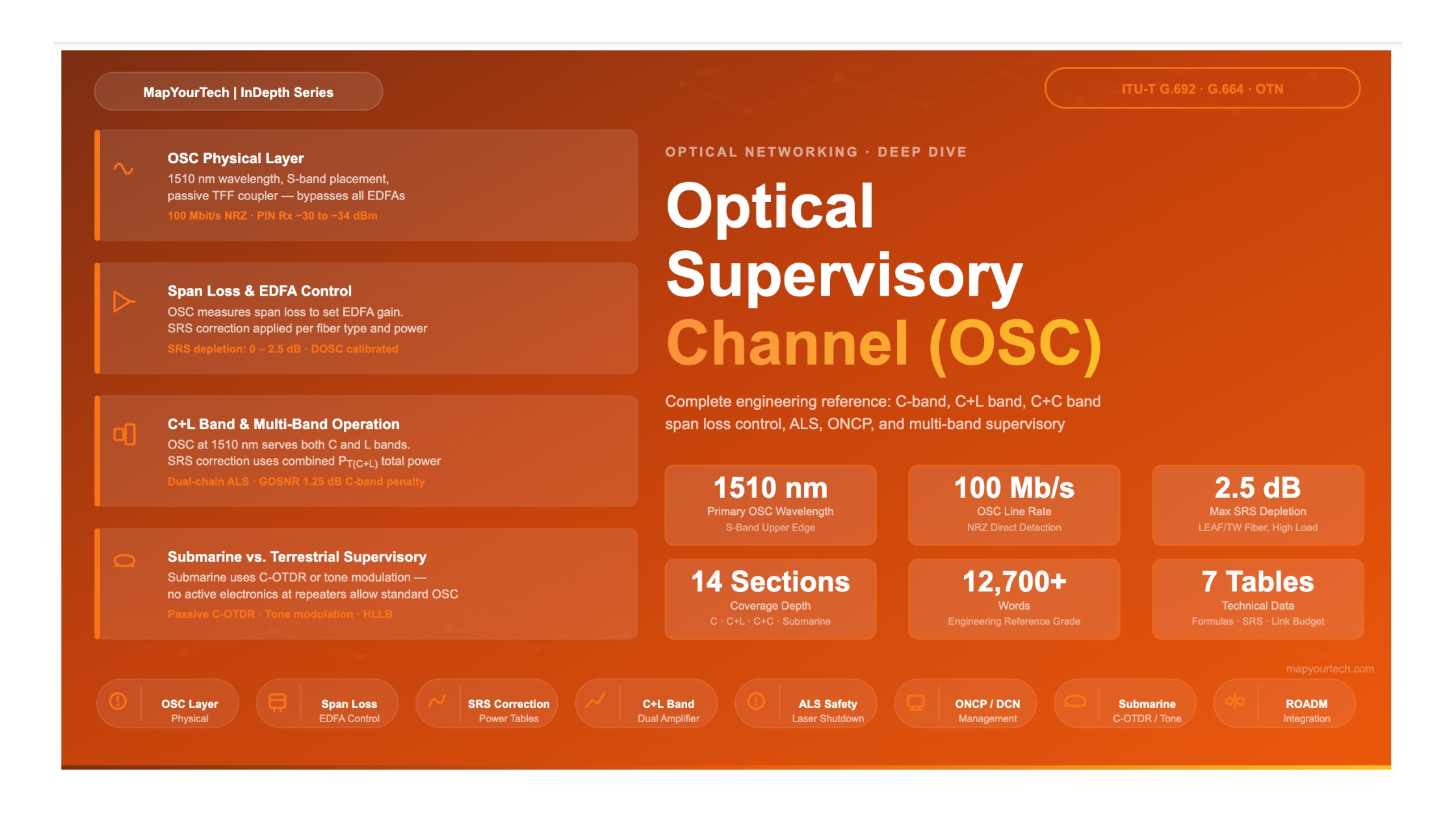

Optical Supervisory Channel (OSC)
Function, Wavelength, and Data Format in DWDM Systems — A comprehensive engineering reference covering OSC purpose, wavelength allocation, payload structure, out-of-band operation, and deployment practice across terrestrial and submarine optical networks.
1. Introduction
Dense Wavelength Division Multiplexing (DWDM) allows dozens to hundreds of high-capacity optical channels to share a single fiber simultaneously. Managing that fiber — confirming amplifiers are healthy, measuring span loss, detecting fiber cuts, coordinating automatic laser shutdown, and carrying software updates to remote nodes — requires a dedicated, always-available communication path that is completely independent of the traffic channels it supervises. That path is the Optical Supervisory Channel (OSC).
The OSC is a low-speed, out-of-band optical signal that travels on the same fiber as the DWDM traffic channels but at a wavelength that sits deliberately outside the main transmission band. Because it is separated in wavelength, the OSC passes through multiplexers and demultiplexers by a different route, bypassing the erbium-doped fiber amplifiers (EDFAs) that boost the traffic channels. This design gives the OSC a unique property: it continues to function even when all traffic channels are dark, and it can survive — or more precisely, still be received — when the EDFA chain along a span is interrupted.
This article provides a complete engineering reference for the OSC: its historical background, wavelength selection rationale, physical layer characteristics, data payload content, interaction with amplifier control systems, behavior in ROADM and submarine networks, and the practical engineering considerations that govern its deployment.
This article covers C-band DWDM systems with OSC at 1510 nm and 1625 nm. Submarine optical supervisory approaches, which use different techniques including passive loopback and OTDR probing rather than a conventional in-band OSC, are discussed in Section 8 for comparison purposes.
2. Historical Background and Standards Context
Early point-to-point optical transmission systems in the 1980s and early 1990s used electrical regenerators at every amplification site. Because the regenerators were fully electrical, the network management path was built into the overhead bytes of the SDH/SONET frame — there was no need for a separate optical management signal. As optical amplifiers replaced electrical regenerators, a problem emerged: how do you communicate with amplifier nodes that have no electrical regeneration, and therefore no SDH framing from which to extract an embedded management channel?
The answer the industry converged on was a separate optical wavelength, outside the signal band, dedicated entirely to supervision. ITU-T Recommendation G.692, which covers optical interfaces for multi-channel systems with optical amplifiers, formally introduced and described the concept of the Optical Supervisory Channel. The S-band (1 460 nm to 1 530 nm) was identified as a region where some wavelengths may be reserved for the OSC, specifically because it falls below the C-band erbium gain window, allowing the OSC to be added and dropped at each node without entering or exiting the EDFA gain medium.
Over time, equipment vendors settled on practical implementations. The 1510 nm wavelength became the most widely deployed OSC wavelength for C-band DWDM systems. In networks where the L-band is also active, or where the 1510 nm region is potentially affected by Stimulated Raman Scattering power depletion from high loaded fiber, the 1625 nm wavelength — sitting just at the edge of the defined L-band and near the U-band boundary — is used as an alternative. Some vendors also use 1480 nm or 1490 nm in certain product lines; the key requirement is that the chosen wavelength must be outside the EDFA gain spectrum so the OSC can be passively added and dropped at every amplifier site.
- The OSC arose from the need to manage amplifier nodes that lack electrical regeneration and SDH overhead extraction.
- ITU-T G.692 formally recognized the OSC as part of multi-channel amplified system architecture.
- The 1510 nm wavelength is the most common OSC implementation in C-band DWDM systems globally.
- The OSC wavelength must fall outside the EDFA gain band to enable passive add/drop at every node.
3. OSC Wavelength Selection and Spectral Placement
3.1 Why Out-of-Band Placement is Essential
The EDFA amplifies wavelengths within its gain band, which spans approximately 1525 nm to 1565 nm for the C-band and 1570 nm to 1610 nm for the L-band. Any optical signal placed within these ranges will be amplified by every in-line EDFA along the link. For an OSC, amplification along the line is undesirable for two reasons. First, the amplified spontaneous emission (ASE) noise accumulated over a long chain of EDFAs would degrade the OSC's signal-to-noise ratio. Second, amplifying the OSC within the same EDFA as the traffic channels would require the EDFA control algorithm to account for OSC power when calculating total input power and setting gain — complicating gain-control logic. Placing the OSC outside the EDFA gain band avoids both problems entirely.
The ITU-T spectral band definitions are directly relevant here. The S-band (1 460 nm to 1 530 nm) is specifically noted as a region where some wavelengths may be reserved for the OSC. The 1510 nm choice sits comfortably in the upper S-band, close enough to the C-band that passive thin-film filter technology can achieve good isolation, yet far enough below 1530 nm to be completely outside the EDFA gain region. At 1510 nm, standard single-mode fiber has an attenuation of approximately 0.23 dB/km — slightly higher than at 1550 nm, but entirely acceptable for a low-speed supervisory signal over typical span lengths of 60 to 120 km.
3.2 The 1510 nm Choice and Practical Deployment
The 1510 nm OSC is deployed as a Small Form-factor Pluggable (SFP) transceiver on the ROADM or ILAN (In-Line Amplifier Node) card. The project documentation from a ROADM implementation confirms this directly: the card includes a 1510 nm SFP for OSC transmission at 100 Mbit/s, supporting specific SFP module types that meet the required optical interface specifications. The OSC SFP is distinct from any DWDM client transceiver — it operates at a fixed, non-tunable wavelength and typically uses a simple direct-detection PIN receiver, not the sophisticated coherent DSP used for traffic channels.
At every amplifier or ROADM site, the OSC is optically added to and dropped from the main fiber using a passive wavelength coupler, sometimes called an OSC coupler or thin-film filter. This component transparently passes the C-band (and L-band where applicable) signal through to the EDFA, while splitting out the 1510 nm OSC power to the local OSC receiver. On the transmit side, a new OSC signal at 1510 nm is added back onto the fiber output. This means the OSC is regenerated electrically at every node — it does not pass through amplifiers but is instead terminated, processed, and re-originated at each site.
3.3 The 1625 nm Alternative
For systems where the L-band extends to 1625 nm, or where the 1510 nm OSC is subject to excessive power depletion by Stimulated Raman Scattering (SRS) from a heavily loaded fiber, a 1625 nm OSC provides an alternative. At 1625 nm, the wavelength sits at the boundary of the L-band as defined by ITU-T (1 565 nm to 1 625 nm) and approaches the U-band (1 625 nm to 1 675 nm). The U-band is defined by ITU-T specifically for maintenance functions including OTDR testing and fiber identification — traffic is not foreseen there. Using 1625 nm for the OSC therefore places it in a region reserved for non-traffic purposes, consistent with the original intent.
Read the Full Analysis with Premium
The remaining 89% of this article — the design numbers, trade-offs and field guidance — is part of MapYourTech Premium, along with the full premium library, courses and professional tools.


