Animated CTA Banner
MapYourTech
MapYourTech has always been about YOUR tech journey, YOUR questions, YOUR thoughts, and most importantly, YOUR growth. It’s a space where we "Map YOUR Tech" experiences and empower YOUR ambitions.
To further enhance YOUR experience, we are working on delivering a professional, fully customized platform tailored to YOUR needs and expectations.
Thank you for the love and support over the years. It has always motivated us to write more, share practical industry insights, and bring content that empowers and inspires YOU to excel in YOUR career.
We truly believe in our tagline:
“Share, explore, and inspire with the tech inside YOU!”
Let us know what YOU would like to see next! Share YOUR thoughts and help us deliver content that matters most to YOU.
Share YOUR Feedback
Category

Interviews

Category

The role of an Network Engineer is rapidly evolving with the increasing demand for automation to manage complex networks effectively. Whether you’re preparing for a job posting at Amazon Web Services (AWS) or Google or any other leading technology company, having a solid foundation in network engineering combined with proficiency in automation is essential. During my experience so far,I myself have appeared in multiple interviews and have interviewed multiple candidates  where I have noticed that since most of the current networking companies have robust software infrastructure built already  with software engineers ;network engineers either don’t have to write code or they don’t get chance to write script and codes. This makes them a bit hesitant answering automation related questions and some time even they say “I don’t know automation” which I feel not the right thing because I am sure they have either written a small macro in microsoft excel ,or a small script to perform some calculation, or a program to telnet device and do some operation.So be confident to realise your potential and ready to say “I have written few or small scripts that were needed to expedite my work but if it is needed to write some code with current profile ,I can ramp-up fast and can wrote as I am open to learn and explore more after all its just a language to communicate to machine to perform some task and its learnable”.

This article provides foundational information on Python programming, focusing on lists, dictionaries, tuples, mutability, loops, and more, to help you prepare for roles that require both network engineering knowledge and automation skills.

An  Network Engineer typically handles the following responsibilities:

  • Design and Implementation: Build and deploy  networking devices like optical, switches ,routers etc, including DWDM,IP-MPLS,OSPF,BGP etc and other advanced technologies.
  • Network Scaling: Enhance and scale network designs to meet increasing demands.
  • Process Development: Create and refine processes for network operation and deployment.
  • Cross-Department Collaboration: Work with other teams to design and implement network solutions.
  • Standards Compliance: Ensure network adherence to industry and company standards.
  • Change Management: Review and implement network changes to improve performance and reliability.
  • Operational Excellence: Lead projects to enhance network quality and dependability.
  • Problem-Solving and Innovation: Troubleshoot complex issues and develop innovative solutions for network challenges.

Preparing for the Interview

Understanding Core or Leadership Principles

Many companies, like AWS, Google emphasize specific leadership principles or core values. Reflect on your experiences and prepare to discuss how you have applied these principles in your work. Last year I wrote an article in reference to AWS which you can visit here  

Some of the common Leadership Principles or core/mission values are
Behavioural Interview Questions

Expect behavioural questions that assess your problem-solving skills and past experiences. Use the STAR method (Situation, Task, Action, Result) to structure your responses.Most of the fair hire companies will have page dedicated to their hiring process which I will strongly encourage everyone to visit their page like

 Now lets dive into the important piece of this article  because we are still a little far from the point where nobody needs to write code but AI will do all necessary code for users by basic autosuggestions statements.

Automation Warm-up session

Pretty much every service provider is using python at this point of time so lets get to know some of the things that will build readers foundation and remove the fear to appear for interviews that has automation as core skill. Just prepare these by heart and I can assure you will do good with the interviews 

1. Variables and Data Types

Variables store information that can be used and manipulated in your code. Python supports various data types, including integers, floats, strings, and booleans.

# Variables and data types
device_name = "Router1"  # String
status = "Active"  # String
port_count = 24  # Integer
error_rate = 0.01  # Float
is_operational = True  # Boolean

print(f"Device: {device_name}, Status: {status}, Ports: {port_count}, Error Rate: {error_rate}, Operational: {is_operational}")
2. Lists

Lists are mutable sequences that can store a collection of items. Lists allow you to store and manipulate a collection of items.

# Creating and manipulating lists
devices = ["Router1", "Switch1", "Router2", "Switch2"]

# Accessing list elements
print(devices[0])  # Output: Router1

# Adding an element
devices.append("Router3")
print(devices)  # Output: ["Router1", "Switch1", "Router2", "Switch2", "Router3"]

# Removing an element
devices.remove("Switch1")
print(devices)  # Output: ["Router1", "Router2", "Switch2", "Router3"]

# Iterating through a list
for device in devices:
    print(device)
3. Dictionaries
# Creating and manipulating dictionaries
device_statuses = {
    "Router1": "Active",
    "Switch1": "Inactive",
    "Router2": "Active",
    "Switch2": "Active"
}

# Accessing dictionary values
print(device_statuses["Router1"])  # Output: Active

# Adding a key-value pair
device_statuses["Router3"] = "Active"
print(device_statuses)  # Output: {"Router1": "Active", "Switch1": "Inactive", "Router2": "Active", "Switch2": "Active", "Router3": "Active"}

# Removing a key-value pair
del device_statuses["Switch1"]
print(device_statuses)  # Output: {"Router1": "Active", "Router2": "Active", "Switch2": "Active", "Router3": "Active"}

# Iterating through a dictionary
for device, status in device_statuses.items():
    print(f"Device: {device}, Status: {status}")

Dictionaries are mutable collections that store items in key-value pairs. They are useful for storing related data.

4. Tuples

Tuples are immutable sequences, meaning their contents cannot be changed after creation. They are useful for storing fixed collections of items.

# Creating and using tuples
network_segment = ("192.168.1.0", "255.255.255.0")

# Accessing tuple elements
print(network_segment[0])  # Output: 192.168.1.0

# Tuples are immutable
# network_segment[0] = "192.168.2.0"  # This will raise an error
5. Mutability and Immutability

Understanding the concept of mutability and immutability is crucial for effective programming.

  • Mutable objects: Can be changed after creation (e.g., lists, dictionaries).
  • Immutable objects: Cannot be changed after creation (e.g., tuples, strings).
# Example of mutability
devices = ["Router1", "Switch1"]
devices.append("Router2")
print(devices)  # Output: ["Router1", "Switch1", "Router2"]

# Example of immutability
network_segment = ("192.168.1.0", "255.255.255.0")
# network_segment[0] = "192.168.2.0"  # This will raise an error
6. Conditional Statements and Loops

Control the flow of your program using conditional statements and loops.

# Conditional statements
device = "Router1"
status = "Active"

if status == "Active":
    print(f"{device} is operational.")
else:
    print(f"{device} is not operational.")

# Loops
# For loop
for device in devices:
    print(device)

# While loop
count = 0
while count < 3:
    print(count)
    count += 1
7. Functions

Functions are reusable blocks of code that perform a specific task.

# Defining and using functions
def check_device_status(device, status):
    if status == "Active":
        return f"{device} is operational."
    else:
        return f"{device} is not operational."

# Calling a function
result = check_device_status("Router1", "Active")
print(result)  # Output: Router1 is operational.
8. File Handling

Reading from and writing to files is essential for automating tasks that involve data storage.

# Writing to a file
with open("device_statuses.txt", "w") as file:
    for device, status in device_statuses.items():
        file.write(f"{device}: {status}\n")

# Reading from a file
with open("device_statuses.txt", "r") as file:
    content = file.read()
    print(content)
9. Using Libraries

Python libraries extend the functionality of your code. For network automation, libraries like paramiko and netmiko are invaluable.

# Using the json library to work with JSON data
import json

# Convert dictionary to JSON
device_statuses_json = json.dumps(device_statuses)
print(device_statuses_json)

# Parse JSON back to dictionary
parsed_device_statuses = json.loads(device_statuses_json)
print(parsed_device_statuses)

Advanced Python for Network Automation

1. Network Automation Libraries

Utilize libraries such as paramiko for SSH connections, netmiko for multi-vendor device connections, and pyntc for network management.

2. Automating SSH with Paramiko
import paramiko

def ssh_to_device(ip, username, password, command):
    ssh = paramiko.SSHClient()
    ssh.set_missing_host_key_policy(paramiko.AutoAddPolicy())
    ssh.connect(ip, username=username, password=password)
    stdin, stdout, stderr = ssh.exec_command(command)
    return stdout.read().decode()

# Example usage
output = ssh_to_device("192.168.1.1", "admin", "password", "show ip interface brief")
print(output)
3. Automating Network Configuration with Netmiko
from netmiko import ConnectHandler

device = {
    'device_type': 'cisco_ios',
    'host': '192.168.1.1',
    'username': 'admin',
    'password': 'password',
}

net_connect = ConnectHandler(**device)
output = net_connect.send_command("show ip interface brief")
print(output)
4. Using Telnet with telnetlib
import telnetlib

def telnet_to_device(host, port, username, password, command):
    try:
        # Connect to the device
        tn = telnetlib.Telnet(host, port)
        
        # Read until the login prompt
        tn.read_until(b"login: ")
        tn.write(username.encode('ascii') + b"\n")
        
        # Read until the password prompt
        tn.read_until(b"Password: ")
        tn.write(password.encode('ascii') + b"\n")
        
        # Execute the command
        tn.write(command.encode('ascii') + b"\n")
        
        # Wait for command execution and read the output
        output = tn.read_all().decode('ascii')
        
        # Close the connection
        tn.close()
        
        return output
    except Exception as e:
        return str(e)

# Example usage
host = "192.168.1.1"
port = 3083
username = "admin"
password = "password"
command = "rtrv-alm-all:::123;"

output = telnet_to_device(host, port, username, password, command)
print(output)
5. Using SSH with paramiko
import paramiko

def ssh_to_device(host, port, username, password, command):
    try:
        # Create an SSH client
        ssh = paramiko.SSHClient()
        
        # Automatically add the device's host key (not recommended for production)
        ssh.set_missing_host_key_policy(paramiko.AutoAddPolicy())
        
        # Connect to the device
        ssh.connect(host, port=port, username=username, password=password)
        
        # Execute the command
        stdin, stdout, stderr = ssh.exec_command(command)
        
        # Read the command output
        output = stdout.read().decode()
        
        # Close the connection
        ssh.close()
        
        return output
    except Exception as e:
        return str(e)

# Example usage
host = "192.168.1.1"
port = 3083
username = "admin"
password = "password"
command = "rtrv-alm-all:::123;"

output = ssh_to_device(host, port, username, password, command)
print(output)
6. Using Telnet with telnetlib with list of devices.
import telnetlib

def telnet_to_device(host, port, username, password, command):
    try:
        # Connect to the device
        tn = telnetlib.Telnet(host, port)
        
        # Read until the login prompt
        tn.read_until(b"login: ")
        tn.write(username.encode('ascii') + b"\n")
        
        # Read until the password prompt
        tn.read_until(b"Password: ")
        tn.write(password.encode('ascii') + b"\n")
        
        # Execute the command
        tn.write(command.encode('ascii') + b"\n")
        
        # Wait for command execution and read the output
        output = tn.read_all().decode('ascii')
        
        # Close the connection
        tn.close()
        
        return output
    except Exception as e:
        return str(e)

# List of devices
devices = [
    {"host": "192.168.1.1", "port": 3083, "username": "admin", "password": "password"},
    {"host": "192.168.1.2", "port": 3083, "username": "admin", "password": "password"},
    {"host": "192.168.1.3", "port": 3083, "username": "admin", "password": "password"}
]

command = "rtrv-alm-all:::123;"

# Execute command on each device
for device in devices:
    output = telnet_to_device(device["host"], device["port"], device["username"], device["password"], command)
    print(f"Output from {device['host']}:\n{output}\n")

or

import telnetlib

def telnet_to_device(host, port, username, password, command):
    try:
        # Connect to the device
        tn = telnetlib.Telnet(host, port)
        
        # Read until the login prompt
        tn.read_until(b"login: ")
        tn.write(username.encode('ascii') + b"\n")
        
        # Read until the password prompt
        tn.read_until(b"Password: ")
        tn.write(password.encode('ascii') + b"\n")
        
        # Execute the command
        tn.write(command.encode('ascii') + b"\n")
        
        # Wait for command execution and read the output
        output = tn.read_all().decode('ascii')
        
        # Close the connection
        tn.close()
        
        return output
    except Exception as e:
        return str(e)

# List of device IPs
device_ips = [
    "192.168.1.1",
    "192.168.1.2",
    "192.168.1.3"
]

# Common credentials and port
port = 3083
username = "admin"
password = "password"
command = "rtrv-alm-all:::123;"

# Execute command on each device
for ip in device_ips:
    output = telnet_to_device(ip, port, username, password, command)
    print(f"Output from {ip}:\n{output}\n")
7. Using SSH with paramiko with list of devices
import paramiko

def ssh_to_device(host, port, username, password, command):
    try:
        # Create an SSH client
        ssh = paramiko.SSHClient()
        
        # Automatically add the device's host key (not recommended for production)
        ssh.set_missing_host_key_policy(paramiko.AutoAddPolicy())
        
        # Connect to the device
        ssh.connect(host, port=port, username=username, password=password)
        
        # Execute the command
        stdin, stdout, stderr = ssh.exec_command(command)
        
        # Read the command output
        output = stdout.read().decode()
        
        # Close the connection
        ssh.close()
        
        return output
    except Exception as e:
        return str(e)

# List of devices
devices = [
    {"host": "192.168.1.1", "port": 3083, "username": "admin", "password": "password"},
    {"host": "192.168.1.2", "port": 3083, "username": "admin", "password": "password"},
    {"host": "192.168.1.3", "port": 3083, "username": "admin", "password": "password"}
]

command = "rtrv-alm-all:::123;"

# Execute command on each device
for device in devices:
    output = ssh_to_device(device["host"], device["port"], device["username"], device["password"], command)
    print(f"Output from {device['host']}:\n{output}\n")

or

import paramiko

def ssh_to_device(host, port, username, password, command):
    try:
        # Create an SSH client
        ssh = paramiko.SSHClient()
        
        # Automatically add the device's host key (not recommended for production)
        ssh.set_missing_host_key_policy(paramiko.AutoAddPolicy())
        
        # Connect to the device
        ssh.connect(host, port=port, username=username, password=password)
        
        # Execute the command
        stdin, stdout, stderr = ssh.exec_command(command)
        
        # Read the command output
        output = stdout.read().decode()
        
        # Close the connection
        ssh.close()
        
        return output
    except Exception as e:
        return str(e)

# List of device IPs
device_ips = [
    "192.168.1.1",
    "192.168.1.2",
    "192.168.1.3"
]

# Common credentials and port
port = 3083
username = "admin"
password = "password"
command = "rtrv-alm-all:::123;"

# Execute command on each device
for ip in device_ips:
    output = ssh_to_device(ip, port, username, password, command)
    print(f"Output from {ip}:\n{output}\n")

Proficiency in Python and understanding the foundational concepts of lists, dictionaries, tuples, mutability, loops, and functions are crucial for automating tasks in network engineering. By practising and mastering these skills, you can enhance your problem-solving capabilities, improve network efficiency, and contribute to innovative solutions within your organization.

This guide serves as a starting point for your preparation. Practice coding regularly, explore advanced topics, and stay updated with the latest advancements in network automation. With dedication and the right preparation, you’ll be well-equipped to excel in any network engineering role.

If you feel that any other information that can help you being reader and for others ,feel free to leave comment and I will try to incorporate those in future.

All the best!

References

Navigating a job interview successfully is crucial for any job seeker looking to make a positive impression. This often intimidating process can be transformed into an empowering opportunity to showcase your strengths and fit for the role. Here are refined strategies and insights to help you excel in your next job interview.

1. Focus on Positive Self-Representation

When asked to “tell me about yourself,” this is your chance to control the narrative. This question is a golden opportunity to succinctly present yourself by focusing on attributes that align closely with the job requirements and the company’s culture. Begin by identifying your key personality traits and how they enhance your professional capabilities. Consider what the company values and how your experiences and strengths play into these areas. Practicing your delivery can boost your confidence, enabling you to articulate a clear and focused response that demonstrates your suitability for the role. For example, explaining how your collaborative nature and creativity in problem-solving match the company’s emphasis on teamwork and innovation can set a strong tone for the interview.

2. Utilize the Power of Storytelling

Personal stories are not just engaging; they are a compelling way to illustrate your skills and character to the interviewer. Think about your past professional experiences and select stories that reflect the qualities the employer is seeking. These narratives should go beyond simply stating facts; they should convey your personal values, decision-making processes, and the impact of your actions. Reflect on challenges you’ve faced and how you’ve overcome them, focusing on the insights gained and the results driven. This method helps the interviewer see beyond your resume to the person behind the accomplishments.

3. Demonstrate Vulnerability and Growth

It’s important to be seen as approachable and self-aware, which means acknowledging not just successes but also vulnerabilities. Discussing a past failure or challenge and detailing what you learned from it can significantly enhance your credibility. This openness shows that you are capable of self-reflection and willing to grow from your experiences. Employers value candidates who are not only skilled but are also resilient and ready to adapt based on past lessons.

4. Showcase Your Authentic Self

Authenticity is key in interviews. It’s essential to present yourself truthfully in terms of your values, preferences, and style. This could relate to your cultural background, lifestyle choices, or personal philosophies. A company that respects and values diversity will appreciate this honesty and is more likely to be a good fit for you in the long term. Displaying your true self can also help you feel more at ease during the interview process, as it reduces the pressure to conform to an idealized image.

5. Engage with Thoughtful Questions

Asking insightful questions during an interview can set you apart from other candidates. It shows that you are thoughtful and have a genuine interest in the role and the company. Inquire about the team dynamics, the company’s approach to feedback and growth, and the challenges currently facing the department. These questions can reveal a lot about the internal workings of the company and help you determine if the environment aligns with your professional goals and values.

Conclusion

Preparing for a job interview involves more than rehearsing standard questions; it requires a strategic approach to how you present your professional narrative. By emphasising a positive self-presentation, employing storytelling, showing vulnerability, maintaining authenticity, and asking engaging questions, you can make a strong impression. Each interview is an opportunity not only to showcase your qualifications but also to find a role and an organisation where you can thrive and grow.

References

  • Self experience
  • Internet
  • hbr


Optical fiber, often referred to as “light pipe,” is a technology that has revolutionised the way we transmit data and communicate. This blog will give some context to optical fiber communications enthusiasts on few well known facts. Here are 30 fascinating facts about optical fiber that highlight its significance and versatility:

1. Light-Speed Data Transmission: Optical fibers transmit data at the speed of light, making them the fastest means of communication.

2. Thin as a Hair: Optical fibers are incredibly thin, often as thin as a human hair, but they can carry massive amounts of data.

3. Immunity to Interference: Unlike copper cables, optical fibers are immune to electromagnetic interference, ensuring data integrity.

4. Long-Distance Connectivity: Optical fibers can transmit data over incredibly long distances without significant signal degradation.

5. Secure Communication: Fiber-optic communication is highly secure because it’s challenging to tap into the signal without detection.

6. Medical Applications: Optical fibers are used in medical devices like endoscopes and laser surgery equipment.

7. Internet Backbone: The global internet relies heavily on optical fiber networks for data transfer.

8. Fiber to the Home (FTTH): FTTH connections offer high-speed internet access directly to residences using optical fibers.

9. Undersea Cables: Optical fibers laid on the ocean floor connect continents, enabling international communication.

10. Laser Light Communication: Optical fibers use lasers to transmit data, ensuring precision and clarity.

11. Multiplexing: Wavelength division multiplexing (WDM) allows multiple signals to travel simultaneously on a single optical fiber.

12. Fiber-Optic Sensors: Optical fibers are used in various sensors for measuring temperature, pressure, and more.

13. Low Latency: Optical fibers offer low latency, crucial for real-time applications like online gaming and video conferencing.

14. Military and Defense: Fiber-optic technology is used in secure military communication systems.

15. Fiber-Optic Art: Some artists use optical fibers to create stunning visual effects in their artworks.

16. Global Internet Traffic: The majority of global internet traffic travels through optical fiber cables.

17. High-Bandwidth Capacity: Optical fibers have high bandwidth, accommodating the ever-increasing data demands.

18. Minimal Signal Loss: Signal loss in optical fibers is minimal compared to traditional cables.

19. Fiber-Optic Lighting: Optical fibers are used in decorative and functional lighting applications.

20. Space Exploration: Optical fibers are used in space missions to transmit data from distant planets.

21. Cable Television: Many cable TV providers use optical fibers to deliver television signals.

22. Internet of Things (IoT): IoT devices benefit from the reliability and speed of optical fiber networks.

23. Fiber-Optic Internet Providers: Some companies specialize in providing high-speed internet solely through optical fibers.

24. Quantum Communication: Optical fibers play a crucial role in quantum communication experiments.

25. Energy Efficiency: Optical fibers are energy-efficient, contributing to greener technology.

26. Data Centers: Data centers rely on optical fibers for internal and external connectivity.

27. Fiber-Optic Decor: Optical fibers are used in architectural designs to create stunning visual effects.

28. Telemedicine: Remote medical consultations benefit from the high-quality video transmission via optical fibers.

29. Optical Fiber Artifacts: Some museums exhibit historical optical fiber artifacts.

30. Future Innovations: Ongoing research promises even faster and more efficient optical fiber technologies.


As communication networks become increasingly dependent on fiber-optic technology, it is essential to understand the quality of the signal in optical links. The two primary parameters used to evaluate the signal quality are Optical Signal-to-Noise Ratio (OSNR) and Q-factor. In this article, we will explore what OSNR and Q-factor are and how they are interdependent with examples for optical link.

Table of Contents

  1. Introduction
  2. What is OSNR?
    • Definition and Calculation of OSNR
  3. What is Q-factor?
    • Definition and Calculation of Q-factor
  4. OSNR and Q-factor Relationship
  5. Examples of OSNR and Q-factor Interdependency
    • Example 1: OSNR and Q-factor for Single Wavelength System
    • Example 2: OSNR and Q-factor for Multi-Wavelength System
  6. Conclusion
  7. FAQs

1. Introduction

Fiber-optic technology is the backbone of modern communication systems, providing fast, secure, and reliable transmission of data over long distances. However, the signal quality of an optical link is subject to various impairments, such as attenuation, dispersion, and noise. To evaluate the signal quality, two primary parameters are used – OSNR and Q-factor.

In this article, we will discuss what OSNR and Q-factor are, how they are calculated, and their interdependency in optical links. We will also provide examples to help you understand how the OSNR and Q-factor affect optical links.

2. What is OSNR?

OSNR stands for Optical Signal-to-Noise Ratio. It is a measure of the signal quality of an optical link, indicating how much the signal power exceeds the noise power. The higher the OSNR value, the better the signal quality of the optical link.

Definition and Calculation of OSNR

The OSNR is calculated as the ratio of the optical signal power to the noise power within a specific bandwidth. The formula for calculating OSNR is as follows:

OSNR (dB) = 10 log10 (Signal Power / Noise Power)

3. What is Q-factor?

Q-factor is a measure of the quality of a digital signal in an optical communication system. It is a function of the bit error rate (BER), signal power, and noise power. The higher the Q-factor value, the better the quality of the signal.

Definition and Calculation of Q-factor

The Q-factor is calculated as the ratio of the distance between the average signal levels of two adjacent symbols to the standard deviation of the noise. The formula for calculating Q-factor is as follows:

Q-factor = (Signal Level 1 – Signal Level 2) / Noise RMS

4. OSNR and Q-factor Relationship

OSNR and Q-factor are interdependent parameters, meaning that changes in one parameter affect the other. The relationship between OSNR and Q-factor is a logarithmic one, which means that a small change in the OSNR can lead to a significant change in the Q-factor.

Generally, the Q-factor increases as the OSNR increases, indicating a better signal quality. However, at high OSNR values, the Q-factor reaches a saturation point, and further increase in the OSNR does not improve the Q-factor.

5. Examples of OSNR and Q-factor Interdependency

Example 1: OSNR and Q-factor for Single Wavelength System

In a single wavelength system, the OSNR and Q-factor have a direct relationship. An increase in the OSNR improves the Q-factor, resulting in a better signal quality. For instance, if the OSNR of a single wavelength system increases from 20 dB to 30 dB,

the Q-factor also increases, resulting in a lower BER and better signal quality. Conversely, a decrease in the OSNR degrades the Q-factor, leading to a higher BER and poor signal quality.

Example 2: OSNR and Q-factor for Multi-Wavelength System

In a multi-wavelength system, the interdependence of OSNR and Q-factor is more complex. The OSNR and Q-factor of each wavelength in the system can vary independently, and the overall system performance depends on the worst-performing wavelength.

For example, consider a four-wavelength system, where each wavelength has an OSNR of 20 dB, 25 dB, 30 dB, and 35 dB. The Q-factor of each wavelength will be different due to the different noise levels. The overall system performance will depend on the wavelength with the worst Q-factor. In this case, if the Q-factor of the first wavelength is the worst, the system performance will be limited by the Q-factor of that wavelength, regardless of the OSNR values of the other wavelengths.

6. Conclusion

In conclusion, OSNR and Q-factor are essential parameters used to evaluate the signal quality of an optical link. They are interdependent, and changes in one parameter affect the other. Generally, an increase in the OSNR improves the Q-factor and signal quality, while a decrease in the OSNR degrades the Q-factor and signal quality. However, the relationship between OSNR and Q-factor is more complex in multi-wavelength systems, and the overall system performance depends on the worst-performing wavelength.

Understanding the interdependence of OSNR and Q-factor is crucial in designing and optimizing optical communication systems for better performance.

7. FAQs

  1. What is the difference between OSNR and SNR? OSNR is the ratio of signal power to noise power within a specific bandwidth, while SNR is the ratio of signal power to noise power over the entire frequency range.
  2. What is the acceptable range of OSNR and Q-factor in optical communication systems? The acceptable range of OSNR and Q-factor varies depending on the specific application and system design. However, a higher OSNR and Q-factor generally indicate better signal quality.
  3. How can I improve the OSNR and Q-factor of an optical link? You can improve the OSNR and Q-factor of an optical link by reducing noise sources, optimizing system design, and using higher-quality components.
  4. Can I measure the OSNR and Q-factor of an optical link in real-time? Yes, you can measure the OSNR and Q-factor of an optical link in real-time using specialized instruments such as an optical spectrum analyzer and a bit error rate tester.
  5. What are the future trends in optical communication systems regarding OSNR and Q-factor? Future trends in optical communication systems include the development of advanced modulation techniques and the use of machine learning algorithms to optimize system performance and improve the OSNR and Q-factor of optical links.

Optical Fiber technology is a game-changer in the world of telecommunication. It has revolutionized the way we communicate and share information. Fiber optic cables are used in most high-speed internet connections, telephone networks, and cable television systems.


What is Fiber Optic Technology?

Fiber optic technology is the use of thin, transparent fibers of glass or plastic to transmit light signals over long distances. These fibers are used in telecommunications to transmit data, video, and voice signals at high speeds and over long distances.

What are Fiber Optic Cables Made Of?

Fiber optic cables are made of thin strands of glass or plastic called fibers. These fibers are surrounded by protective coatings, which make them resistant to moisture, heat, and other environmental factors.

How Does Fiber Optic Technology Work?

Fiber optic technology works by sending pulses of light through the fibers in a cable. These light signals travel through the cable at very high speeds, allowing data to be transmitted quickly and efficiently.

What is an Optical Network?

An optical network is a communication network that uses optical fibers as the primary transmission medium. Optical networks are used for high-speed internet connections, telephone networks, and cable television systems.

What are the Benefits of Fiber Optic Technology?

Fiber optic technology offers several benefits over traditional copper wire technology, including:

  • Faster data transfer speeds
  • Greater bandwidth capacity
  • Less signal loss
  • Resistance to interference from electromagnetic sources
  • Greater reliability
  • Longer lifespan

How Fast is Fiber Optic Internet?

Fiber optic internet can provide download speeds of up to 1 gigabit per second (Gbps) and upload speeds of up to 1 Gbps. This is much faster than traditional copper wire internet connections.

How is Fiber Optic Internet Installed?

Fiber optic internet is installed by running fiber optic cables from a central hub to the homes or businesses that need internet access. The installation process involves digging trenches to bury the cables or running the cables overhead on utility poles.

What are the Different Types of Fiber Optic Cables?

There are two main types of fiber optic cables:

Single-Mode Fiber

Single-mode fiber has a smaller core diameter than multi-mode fiber, which allows it to transmit light signals over longer distances with less attenuation.

Multi-Mode Fiber

Multi-mode fiber has a larger core diameter than single-mode fiber, which allows it to transmit light signals over shorter distances at a lower cost.

What is the Difference Between Single-Mode and Multi-Mode Fiber?

The main difference between single-mode and multi-mode fiber is the size of the core diameter. Single-mode fiber has a smaller core diameter, which allows it to transmit light signals over longer distances with less attenuation. Multi-mode fiber has a larger core diameter, which allows it to transmit light signals over shorter distances at a lower cost.

What is the Maximum Distance for Fiber Optic Cables?

The maximum distance for fiber optic cables depends on the type of cable and the transmission technology used. In general, single-mode fiber can transmit light signals over distances of up to 10 kilometers without the need for signal regeneration, while multi-mode fiber is limited to distances of up to 2 kilometers.

What is Fiber Optic Attenuation?

Fiber optic attenuation refers to the loss of light signal intensity as it travels through a fiber optic cable. Attenuation is caused by factors such as absorption, scattering, and bending of the light signal.

What is Fiber Optic Dispersion?

Fiber optic dispersion refers to the spreading of a light signal as it travels through a fiber optic cable. Dispersion is caused by factors such as the wavelength of the light signal and the length of the cable.

What is Fiber Optic Splicing?

Fiber optic splicing is the process of joining two fiber optic cables together. Splicing is necessary when extending the length of a fiber optic cable or when repairing a damaged cable.

What is the Difference Between Fusion Splicing and Mechanical Splicing?

Fusion splicing is a process in which the two fibers to be joined are fused together using heat. Mechanical splicing is a process in which the two fibers to be joined are aligned and held together using a mechanical splice.

What is Fiber Optic Termination?

Fiber optic termination is the process of connecting a fiber optic cable to a device or equipment. Termination involves attaching a connector to the end of the cable so that it can be plugged into a device or equipment.

What is an Optical Coupler?

An optical coupler is a device that splits or combines light signals in a fiber optic network. Couplers are used to distribute signals from a single source to multiple destinations or to combine signals from multiple sources into a single fiber.

What is an Optical Splitter?

optical splitter is a type of optical coupler that splits a single fiber into multiple fibers. Splitters are used to distribute signals from a single source to multiple destinations.

What is Wavelength-Division Multiplexing?

Wavelength-division multiplexing is a technology that allows multiple signals of different wavelengths to be transmitted over a single fiber. Each signal is assigned a different wavelength, and a multiplexer is used to combine the signals into a single fiber.

What is Dense Wavelength-Division Multiplexing?

Dense wavelength-division multiplexing is a technology that allows multiple signals to be transmitted over a single fiber using very closely spaced wavelengths. DWDM is used to increase the capacity of fiber optic networks.

What is Coarse Wavelength-Division Multiplexing?

Coarse wavelength-division multiplexing is a technology that allows multiple signals to be transmitted over a single fiber using wider-spaced wavelengths than DWDM. CWDM is used for shorter distance applications and lower bandwidth requirements.

What is Bidirectional Wavelength-Division Multiplexing?

Bidirectional wavelength-division multiplexing is a technology that allows signals to be transmitted in both directions over a single fiber. BIDWDM is used to increase the capacity of fiber optic networks.

What is Fiber Optic Testing?

Fiber optic testing is the process of testing the performance of fiber optic cables and components. Testing is done to ensure that the cables and components meet industry standards and to troubleshoot problems in the network.

What is Optical Time-Domain Reflectometer?

An optical time-domain reflectometer is a device used to test fiber optic cables by sending a light signal into the cable and measuring the reflections. OTDRs are used to locate breaks, bends, and other faults in fiber optic cables.

What is Optical Spectrum Analyzer?

An optical spectrum analyzer is a device used to measure the spectral characteristics of a light signal. OSAs are used to analyze the output of fiber optic transmitters and to measure the characteristics of fiber optic components.

What is Optical Power Meter?

An optical power meter is a device used to measure the power of a light signal in a fiber optic cable. Power meters are used to measure the output of fiber optic transmitters and to test the performance of fiber optic cables and components.

What is Fiber Optic Connector?

A fiber optic connector is a device used to attach a fiber optic cable to a device or equipment. Connectors are designed to be easily plugged and unplugged, allowing for easy installation and maintenance.

What is Fiber Optic Adapter?

A fiber optic adapter is a device used to connect two fiber optic connectors together. Adapters are used to extend the length of a fiber optic cable or to connect different types of fiber optic connectors.

What is Fiber Optic Patch Cord?

A fiber optic patch cord is a cable with connectors on both ends used to connect devices or equipment in a fiber optic network. Patch cords are available in different lengths and connector types to meet different network requirements.

What is Fiber Optic Pigtail?

A fiber optic pigtail is a short length of fiber optic cable with a connector on one end and a length of exposed fiber on the other. Pigtails are used to connect fiber optic cables to devices or equipment that require a different type of connector.

What is Fiber Optic Coupler?

A fiber optic coupler is a device used to split or combine light signals in a fiber optic network. Couplers are used to distribute signals from a single source to multiple destinations or to combine signals from multiple sources into a single fiber.

What is Fiber Optic Attenuator?

A fiber optic attenuator is a device used to reduce the power of a light signal in a fiber optic network. Attenuators are used to prevent

signal overload or to match the power levels of different components in the network.

What is Fiber Optic Isolator?

A fiber optic isolator is a device used to prevent light signals from reflecting back into the source. Isolators are used to protect sensitive components in the network from damage caused by reflected light.

What is Fiber Optic Circulator?

A fiber optic circulator is a device used to route light signals in a specific direction in a fiber optic network. Circulators are used to route signals between multiple devices in a network.

What is Fiber Optic Amplifier?

A fiber optic amplifier is a device used to boost the power of a light signal in a fiber optic network. Amplifiers are used to extend the distance that a signal can travel without the need for regeneration.

What is Fiber Optic Modulator?

A fiber optic modulator is a device used to modulate the amplitude or phase of a light signal in a fiber optic network. Modulators are used in applications such as fiber optic communication and sensing.

What is Fiber Optic Switch?

A fiber optic switch is a device used to switch light signals between different fibers in a fiber optic network. Switches are used to route signals between multiple devices in a network.

What is Fiber Optic Demultiplexer?

A fiber optic demultiplexer is a device used to separate multiple signals of different wavelengths that are combined in a single fiber. Demultiplexers are used in wavelength-division multiplexing applications.

What is Fiber Optic Multiplexer?

A fiber optic multiplexer is a device used to combine multiple signals of different wavelengths into a single fiber. Multiplexers are used in wavelength-division multiplexing applications.

What is Fiber Optic Transceiver?

A fiber optic transceiver is a device that combines a transmitter and a receiver into a single module. Transceivers are used to transmit and receive data over a fiber optic network.

What is Fiber Optic Media Converter?

A fiber optic media converter is a device used to convert a fiber optic signal to a different format, such as copper or wireless. Media converters are used to connect fiber optic networks to other types of networks.

What is Fiber Optic Splice Closure?

A fiber optic splice closure is a device used to protect fiber optic splices from environmental factors such as moisture and dust. Splice closures are used in outdoor fiber optic applications.

What is Fiber Optic Distribution Box?

A fiber optic distribution box is a device used to distribute fiber optic signals to multiple devices or equipment. Distribution boxes are used in fiber optic networks to route signals between multiple devices.

What is Fiber Optic Patch Panel?

A fiber optic patch panel is a device used to connect multiple fiber optic cables to a network. Patch panels are used to organize and manage fiber optic connections in a network.

What is Fiber Optic Cable Tray?

A fiber optic cable tray is a device used to support and protect fiber optic cables in a network. Cable trays are used to organize and route fiber optic cables in a network.

What is Fiber Optic Duct?

A fiber optic duct is a device used to protect fiber optic cables from environmental factors such as moisture and dust. Ducts are used in outdoor fiber optic applications.

What is Fiber Optic Raceway?

A fiber optic raceway is a device used to route and protect fiber optic cables in a network. Raceways are used to organize and manage fiber optic connections in a network.

What is Fiber Optic Conduit?

A fiber optic conduit is a protective tube used to house fiber optic cables in a network. Conduits are used in outdoor fiber optic applications to protect cables from environmental factors.

EDFA stands for Erbium-doped fiber amplifier, and it is a type of optical amplifier used in optical communication systems

  1. What is an EDFA amplifier?
  2. How does an EDFA amplifier work?
  3. What is the gain of an EDFA amplifier?
  4. What is the noise figure of an EDFA amplifier?
  5. What is the saturation power of an EDFA amplifier?
  6. What is the output power of an EDFA amplifier?
  7. What is the input power range of an EDFA amplifier?
  8. What is the bandwidth of an EDFA amplifier?
  9. What is the polarization-dependent gain of an EDFA amplifier?
  10. What is the polarization mode dispersion of an EDFA amplifier?
  11. What is the chromatic dispersion of an EDFA amplifier?
  12. What is the pump power of an EDFA amplifier?
  13. What are the types of pump sources used in EDFA amplifiers?
  14. What is the lifetime of an EDFA amplifier?
  15. What is the reliability of an EDFA amplifier?
  16. What is the temperature range of an EDFA amplifier?
  17. What are the applications of EDFA amplifiers?
  18. How can EDFA amplifiers be used in long-haul optical networks?
  19. How can EDFA amplifiers be used in metropolitan optical networks?
  20. How can EDFA amplifiers be used in access optical networks?
  21. What are the advantages of EDFA amplifiers over other types of optical amplifiers?
  22. What are the disadvantages of EDFA amplifiers?
  23. What are the challenges in designing EDFA amplifiers?
  24. How can the performance of EDFA amplifiers be improved?
  25. What is the future of EDFA amplifiers in optical networks?

What is an EDFA Amplifier?

An EDFA amplifier is a type of optical amplifier that uses a doped optical fiber to amplify optical signals. The doping material used in the fiber is erbium, which is added to the fiber core during the manufacturing process. The erbium ions in the fiber core absorb optical signals at a specific wavelength and emit them at a higher energy level, which results in amplification of the optical signal.

How Does an EDFA Amplifier Work?

An EDFA amplifier works on the principle of stimulated emission. When an optical signal enters the doped fiber core, the erbium ions in the fiber absorb the energy from the optical signal and get excited to a higher energy level. The excited erbium ions then emit photons at the same wavelength and in phase with the incoming photons, which results in amplification of the optical signal.

What is the Gain of an EDFA Amplifier?

The gain of an EDFA amplifier is the ratio of output power to input power, expressed in decibels (dB). The gain of an EDFA amplifier depends on the length of the doped fiber, the concentration of erbium ions in the fiber, and the pump power.

What is the Noise Figure of an EDFA Amplifier?

The noise figure of an EDFA amplifier is a measure of the additional noise introduced by the amplifier in the optical signal. It is expressed in decibels (dB) and is a function of the gain and the bandwidth of the amplifier.

What is the Saturation Power of an EDFA Amplifier?

The saturation power of an EDFA amplifier is the input power at which the gain of the amplifier saturates and does not increase further. It depends on the pump power and the length of the doped fiber.

What is the Output Power of an EDFA Amplifier?

The output power of an EDFA amplifier depends on the input power, the gain, and the saturation power of the amplifier. The output power can be increased by increasing the input power or by using multiple stages of amplification.

What is the Input Power Range of an EDFA Amplifier?

The input power range of an EDFA amplifier is the range of input powers that can be amplified without significant distortion or damage to the amplifier. The input power range depends on the saturation power and the noise figure of the amplifier.

What is the Bandwidth of an EDFA Amplifier?

The bandwidth of an EDFA amplifier is the range of wavelengths over which the amplifier can amplify the optical signal. The bandwidth depends on the spectral characteristics of the erbium ions in the fiber and the optical filters used in the amplifier.

What is the Polarization-Dependent Gain of an EDFA Amplifier?

The polarization-dependent gain of an EDFA amplifier is the difference in gain between two orthogonal polarizations of the input signal. It is caused by the birefringence of the doped fiber and can be minimized by using polarization-maintaining fibers and components.

What is the Polarization Mode Dispersion of an EDFA Amplifier?

The polarization mode dispersion of an EDFA amplifier is the differential delay between the two orthogonal polarizations of the input signal. It is caused by the birefringence of the doped fiber and can lead to distortion and signal degradation.

What is the Chromatic Dispersion of an EDFA Amplifier?

The chromatic dispersion of an EDFA amplifier is the differential delay between different wavelengths of the input signal. It is caused by the dispersion of the fiber and can lead to signal distortion and inter-symbol interference.

What is the Pump Power of an EDFA Amplifier?

The pump power of an EDFA amplifier is the power of the pump laser used to excite the erbium ions in the fiber. The pump power is typically in the range of a few hundred milliwatts to a few watts.

What are the Types of Pump Sources Used in EDFA Amplifiers?

The two types of pump sources used in EDFA amplifiers are laser diodes and fiber-coupled laser diodes. Laser diodes are more compact and efficient but require precise temperature control, while fiber-coupled laser diodes are more robust but less efficient.

What is the Lifetime of an EDFA Amplifier?

The lifetime of an EDFA amplifier depends on the quality of the components used and the operating conditions. A well-designed and maintained EDFA amplifier can have a lifetime of several years.

What is the Reliability of an EDFA Amplifier?

The reliability of an EDFA amplifier depends on the quality of the components used and the operating conditions. A well-designed and maintained EDFA amplifier can have a high level of reliability.

What is the Temperature Range of an EDFA Amplifier?

The temperature range of an EDFA amplifier depends on the thermal properties of the components used and the design of the amplifier. Most EDFA amplifiers can operate over a temperature range of -5°C to 70°C.

What are the Applications of EDFA Amplifiers?

EDFA amplifiers are used in a wide range of applications, including long-haul optical networks, metropolitan optical networks, and access optical networks. They are also used in fiber-optic sensors, fiber lasers, and other applications that require optical amplification.

How can EDFA Amplifiers be Used in Long-Haul Optical Networks?

EDFA amplifiers can be used in long-haul optical networks to overcome the signal attenuation caused by the fiber loss. By amplifying the optical signal periodically along the fiber link, the signal can be transmitted over longer distances without the need for regeneration. EDFA amplifiers can also be used in conjunction with other types of optical amplifiers, such as Raman amplifiers, to improve the performance of the optical network.

How can EDFA Amplifiers be Used in Metropolitan Optical Networks?

EDFA amplifiers can be used in metropolitan optical networks to increase the reach and capacity of the network. They can be used to amplify the optical signal in the fiber links between the central office and the remote terminals, as well as in the access network. EDFA amplifiers can also be used to compensate for the loss in passive optical components, such as splitters and couplers.

How can EDFA Amplifiers be Used in Access Optical Networks?

EDFA amplifiers can be used in access optical networks to increase the reach and capacity of the network. They can be used to amplify the optical signal in the fiber links between the central office and the optical network terminals (ONTs), as well as in the distribution network. EDFA amplifiers can also be used to compensate for the loss in passive optical components, such as splitters and couplers.

What are the Advantages of EDFA Amplifiers over Other Types of Optical Amplifiers?

The advantages of EDFA amplifiers over other types of optical amplifiers include high gain, low noise figure, wide bandwidth, and compatibility with other optical components. EDFA amplifiers also have a simple and robust design and are relatively easy to manufacture.

What are the Disadvantages of EDFA Amplifiers?

The disadvantages of EDFA amplifiers include polarization-dependent gain, polarization mode dispersion, and chromatic dispersion. EDFA amplifiers also require high pump powers and precise temperature control, which can increase the cost and complexity of the system.

What are the Challenges in Designing EDFA Amplifiers?

The challenges in designing EDFA amplifiers include minimizing the polarization-dependent gain and polarization mode dispersion, optimizing the pump power and wavelength, and reducing the noise figure and distortion. The design also needs to be robust and reliable, and compatible with other optical components.

How can the Performance of EDFA Amplifiers be Improved?

The performance of EDFA amplifiers can be improved by using polarization-maintaining fibers and components, optimizing the pump power and wavelength, using optical filters to reduce noise and distortion, and using multiple stages of amplification. The use of advanced materials, such as thulium-doped fibers, can also improve the performance of EDFA amplifiers.

What is the Future of EDFA Amplifiers in Optical Networks?

EDFA amplifiers will continue to play an important role in optical networks, especially in long-haul and high-capacity applications. However, new technologies, such as semiconductor optical amplifiers and hybrid amplifiers, are emerging that offer higher performance and lower cost. The future of EDFA amplifiers will depend on their ability to adapt to these new technologies and continue to provide value to the optical networking industry.

Conclusion

EDFA amplifiers are a key component of optical communication systems, providing high gain and low noise amplification of optical signals. Understanding the basics of EDFA amplifiers, including their gain, noise figure, bandwidth, and other characteristics, is essential for anyone interested in optical networking. By answering these 25 questions, we hope to have provided a comprehensive overview of EDFA amplifiers and their applications in optical networks.

FAQs

  1. What is the difference between EDFA and SOA amplifiers?
  2. How can I calculate the gain of an EDFA amplifier?
  3. What is the effect of pump
  4. power on the performance of an EDFA amplifier? 4. Can EDFA amplifiers be used in WDM systems?
  5. How can I minimize the polarization mode dispersion of an EDFA amplifier?
  6. FAQs Answers
  7. The main difference between EDFA and SOA amplifiers is that EDFA amplifiers use a doped fiber to amplify the optical signal, while SOA amplifiers use a semiconductor material.
  8. The gain of an EDFA amplifier can be calculated using the formula: G = 10*log10(Pout/Pin), where G is the gain in decibels, Pout is the output power, and Pin is the input power.
  9. The pump power has a significant impact on the gain and noise figure of an EDFA amplifier. Increasing the pump power can increase the gain and reduce the noise figure, but also increases the risk of nonlinear effects and thermal damage.
  10. Yes, EDFA amplifiers are commonly used in WDM systems to amplify the optical signals at multiple wavelengths simultaneously.
  11. The polarization mode dispersion of an EDFA amplifier can be minimized by using polarization-maintaining fibers and components, and by optimizing the design of the amplifier to reduce birefringence effects.

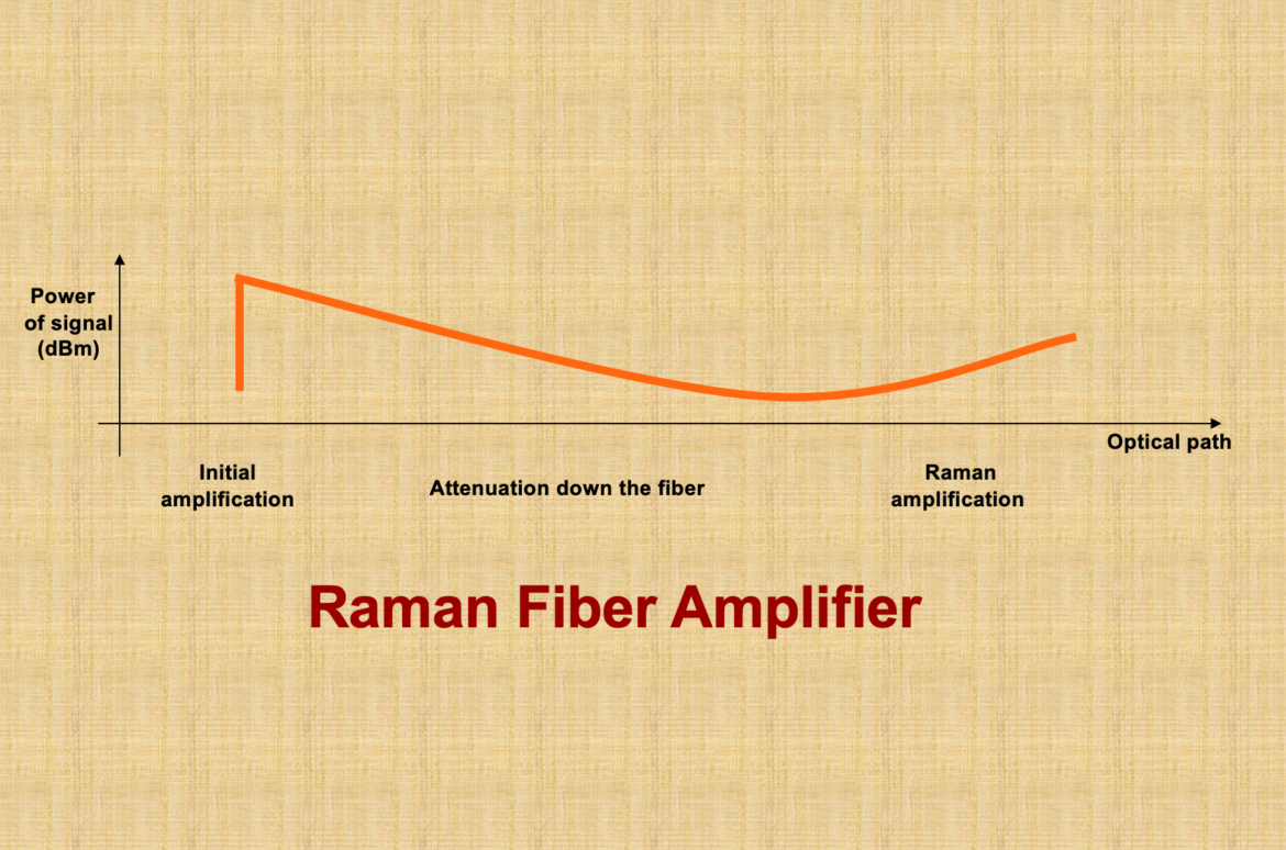
In the context of Raman amplifiers, the noise figure is typically not negative. However, when comparing Raman amplifiers to other amplifiers, such as erbium-doped fiber amplifiers (EDFAs), the effective noise figure may appear to be negative due to the distributed nature of the Raman gain.

The noise figure (NF) is a parameter that describes the degradation of the signal-to-noise ratio (SNR) as the signal passes through a system or device. A higher noise figure indicates a greater degradation of the SNR, while a lower noise figure indicates better performance.

In Raman amplification, the gain is distributed along the transmission fiber, as opposed to being localized at specific points, like in an EDFA. This distributed gain reduces the peak power of the optical signals and the accumulation of noise along the transmission path. As a result, the noise performance of a Raman amplifier can be better than that of an EDFA.

When comparing Raman amplifiers with EDFAs, it is sometimes possible to achieve an effective noise figure that is lower than that of the EDFA. In this case, the difference in noise figure between the Raman amplifier and the EDFA may be considered “negative.” However, this does not mean that the Raman amplifier itself has a negative noise figure; rather, it indicates that the Raman amplifier provides better noise performance compared to the EDFA.

In conclusion, a Raman amplifier itself does not have a negative noise figure. However, when comparing its noise performance to other amplifiers, such as EDFAs, the difference in noise figure may appear to be negative due to the superior noise performance of the Raman amplifier.

To better illustrate the concept of an “effective negative noise figure” in the context of Raman amplifiers, let’s consider an example comparing a Raman amplifier with an EDFA.

Suppose we have a fiber-optic communication system with the following parameters:

  1. Signal wavelength: 1550 nm
  2. Raman pump wavelength: 1450 nm
  3. Transmission fiber length: 100 km
  4. Total signal attenuation: 20 dB
  5. EDFA noise figure: 4 dB

Now, we introduce a Raman amplifier into the system to provide distributed gain along the transmission fiber. Due to the distributed nature of the Raman gain, the accumulation of noise is reduced, and the noise performance is improved.

Let’s assume that the Raman amplifier has an effective noise figure of 1 dB. When comparing the noise performance of the Raman amplifier with the EDFA, we can calculate the difference in noise figure:

Difference in noise figure = Raman amplifier noise figure – EDFA noise figure = 1 dB – 4 dB = -3 dB

In this example, the difference in noise figure is -3 dB, which may be interpreted as an “effective negative noise figure.” It is important to note that the Raman amplifier itself does not have a negative noise figure. The negative value simply represents a superior noise performance when compared to the EDFA.

This example demonstrates that the effective noise figure of a Raman amplifier can be lower than that of an EDFA, resulting in better noise performance and an improved signal-to-noise ratio for the overall system.

The example highlights the advantages of using Raman amplifiers in optical communication systems, especially when it comes to noise performance. In addition to the improved noise performance, there are several other benefits associated with Raman amplifiers:

  1. Broad gain bandwidth: Raman amplifiers can provide gain over a wide range of wavelengths, typically up to 100 nm or more, depending on the pump laser configuration and fiber properties. This makes Raman amplifiers well-suited for dense wavelength division multiplexing (DWDM) systems.
  2. Distributed gain: As previously mentioned, Raman amplifiers provide distributed gain along the transmission fiber. This feature helps to mitigate nonlinear effects, such as self-phase modulation and cross-phase modulation, which can degrade the signal quality and limit the transmission distance.
  3. Compatibility with other optical amplifiers: Raman amplifiers can be used in combination with other optical amplifiers, such as EDFAs, to optimize system performance by leveraging the advantages of each amplifier type.
  4. Flexibility: The performance of Raman amplifiers can be tuned by adjusting the pump laser power, wavelength, and configuration (e.g., co-propagating or counter-propagating). This flexibility allows for the optimization of system performance based on specific network requirements.

As optical communication systems continue to evolve, Raman amplifiers will likely play a significant role in addressing the challenges associated with increasing data rates, transmission distances, and network capacity. Ongoing research and development efforts aim to further improve the performance of Raman amplifiers, reduce costs, and integrate them with emerging technologies, such as software-defined networking (SDN), to enable more intelligent and adaptive optical networks.

  1. What is a Raman amplifier?

A: A Raman amplifier is a type of optical amplifier that utilizes stimulated Raman scattering (SRS) to amplify optical signals in fiber-optic communication systems.

  1. How does a Raman amplifier work?

A: Raman amplification occurs when a high-power pump laser interacts with the optical signal in the transmission fiber, causing energy transfer from the pump wavelength to the signal wavelength through stimulated Raman scattering, thus amplifying the signal.

  1. What is the difference between a Raman amplifier and an erbium-doped fiber amplifier (EDFA)?

A: A Raman amplifier uses stimulated Raman scattering in the transmission fiber for amplification, while an EDFA uses erbium-doped fiber as the gain medium. Raman amplifiers can provide gain over a broader wavelength range and have lower noise compared to EDFAs.

  1. What are the advantages of Raman amplifiers?

A: Advantages of Raman amplifiers include broader gain bandwidth, lower noise, and better performance in combating nonlinear effects compared to other optical amplifiers, such as EDFAs.

  1. What is the typical gain bandwidth of a Raman amplifier?

A: The typical gain bandwidth of a Raman amplifier can be up to 100 nm or more, depending on the pump laser configuration and fiber properties.

  1. What are the key components of a Raman amplifier?

A: Key components of a Raman amplifier include high-power pump lasers, wavelength division multiplexers (WDMs) or couplers, and the transmission fiber itself, which serves as the gain medium.

  1. How do Raman amplifiers reduce nonlinear effects in optical networks?

A: Raman amplifiers can be configured to provide distributed gain along the transmission fiber, reducing the peak power of the optical signals and thus mitigating nonlinear effects such as self-phase modulation and cross-phase modulation.

  1. What are the different types of Raman amplifiers?

A: Raman amplifiers can be classified as discrete Raman amplifiers (DRAs) and distributed Raman amplifiers (DRAs). DRAs use a separate section of fiber as the gain medium, while DRAs provide gain directly within the transmission fiber.

  1. How is a Raman amplifier pump laser configured?

A: Raman amplifier pump lasers can be configured in various ways, such as co-propagating (pump and signal travel in the same direction) or counter-propagating (pump and signal travel in opposite directions) to optimize performance.

  1. What are the safety concerns related to Raman amplifiers?

A: The high-power pump lasers used in Raman amplifiers can pose safety risks, including damage to optical components and potential harm to technicians if proper safety precautions are not followed.

  1. Can Raman amplifiers be used in combination with other optical amplifiers?

A: Yes, Raman amplifiers can be used in combination with other optical amplifiers, such as EDFAs, to optimize system performance by leveraging the advantages of each amplifier type.

  1. How does the choice of fiber type impact Raman amplification?

A: The choice of fiber type can impact Raman amplification efficiency, as different fiber types exhibit varying Raman gain coefficients and effective area, which affect the gain and noise performance.

  1. What is the Raman gain coefficient?

A: The Raman gain coefficient is a measure of the efficiency of the Raman scattering process in a specific fiber. A higher Raman gain coefficient indicates more efficient energy transfer from the pump laser to the optical signal.

  1. What factors impact the performance of a Raman amplifier?

A: Factors impacting Raman amplifier performance include pump laser power and wavelength, fiber type and length, signal wavelength, and the presence of other nonlinear effects.

  1. How does temperature affect Raman amplifier performance?

A: Temperature can affect Raman amplifier performance by influencing the Raman gain coefficient and the efficiency of the stimulated Raman scattering process. Proper temperature management is essential for optimal Raman amplifier performance.

  1. What is the role of a Raman pump combiner?

A: A Raman pump combiner is a device used to combine the output of multiple high-power pump lasers, providing a single high-power pump source to optimize Raman amplifier performance.

  1. How does polarization mode dispersion (PMD) impact Raman amplifiers?

A: PMD can affect the performance of Raman amplifiers by causing variations in the gain and noise characteristics for different polarization states, potentially leading to signal degradation.

  1. How do Raman amplifiers impact optical signal-to-noise ratio (OSNR)?

A: Raman amplifiers can improve the OSNR by providing distributed gain along the transmission fiber and reducing the peak power of the optical signals, which helps to mitigate nonlinear effects and improve signal quality.

  1. What are the challenges in implementing Raman amplifiers?

A: Challenges in implementing Raman amplifiers include the need for high-power pump lasers, proper safety precautions, temperature management, and potential interactions with other nonlinear effects in the fiber-optic system.

  1. What is the future of Raman amplifiers in optical networks?

A: The future of Raman amplifiers in optical networks includes further research and development to optimize performance, reduce costs, and integrate Raman amplifiers with other emerging technologies, such as software-defined networking (SDN), to enable more intelligent and adaptive optical networks.

  1. What is DWDM technology?

A: DWDM stands for Dense Wavelength Division Multiplexing, a technology used in optical networks to increase the capacity of data transmission by combining multiple optical signals with different wavelengths onto a single fiber.

  1. How does DWDM work?

A: DWDM works by assigning each incoming data channel a unique wavelength (or color) of light, combining these channels into a single optical fiber. This allows multiple data streams to travel simultaneously without interference.

  1. What is the difference between DWDM and CWDM?

A: DWDM stands for Dense Wavelength Division Multiplexing, while CWDM stands for Coarse Wavelength Division Multiplexing. The primary difference is in the channel spacing, with DWDM having much closer channel spacing, allowing for more channels on a single fiber.

  1. What are the key components of a DWDM system?

A: Key components of a DWDM system include optical transmitters, multiplexers, optical amplifiers, de-multiplexers, and optical receivers.

  1. What is an Optical Add-Drop Multiplexer (OADM)?

A: An OADM is a device that adds or drops specific wavelengths in a DWDM system while allowing other wavelengths to continue along the fiber.

  1. How does DWDM increase network capacity?

A: DWDM increases network capacity by combining multiple optical signals with different wavelengths onto a single fiber, allowing for simultaneous data transmission without interference.

  1. What is the typical channel spacing in DWDM systems?

A: The typical channel spacing in DWDM systems is 100 GHz or 0.8 nm, although more advanced systems can achieve 50 GHz or even 25 GHz spacing.

  1. What is the role of optical amplifiers in DWDM systems?

A: Optical amplifiers are used to boost the signal strength in DWDM systems, compensating for signal loss and enabling long-distance transmission.

  1. What is the maximum transmission distance for DWDM systems?

A: Maximum transmission distance for DWDM systems varies depending on factors such as channel count, fiber type, and amplification. However, some systems can achieve distances of up to 2,500 km or more.

  1. What are the primary benefits of DWDM?

A: Benefits of DWDM include increased network capacity, scalability, flexibility, and cost-effectiveness.

  1. What are some common applications of DWDM technology?

A: DWDM technology is commonly used in long-haul and metropolitan area networks (MANs), as well as in internet service provider (ISP) networks and data center interconnects.

  1. What is a wavelength blocker?

A: A wavelength blocker is a device that selectively blocks or filters specific wavelengths in a DWDM system.

  1. What are erbium-doped fiber amplifiers (EDFAs)?

A: EDFAs are a type of optical amplifier that uses erbium-doped fiber as the gain medium, providing amplification for DWDM systems.

  1. How does chromatic dispersion impact DWDM systems?

A: Chromatic dispersion is the spreading of an optical signal due to different wavelengths traveling at different speeds in the fiber. In DWDM systems, chromatic dispersion can cause signal degradation and reduce transmission distance.

  1. What is a dispersion compensating module (DCM)?

A: A DCM is a device used to compensate for chromatic dispersion in DWDM systems, improving signal quality and transmission distance.

  1. What is an optical signal-to-noise ratio (OSNR)?

A: OSNR is a measure of the quality of an optical signal in relation to noise in a DWDM system. A higher OSNR indicates better signal quality.

  1. How does polarization mode dispersion (PMD) affect DWDM systems?

A: PMD is a phenomenon where different polarization states of

ight travel at different speeds in the fiber, causing signal distortion and degradation in DWDM systems. PMD can limit the transmission distance and data rates.

  1. What is the role of a dispersion management strategy in DWDM systems?

A: A dispersion management strategy helps to minimize the impact of chromatic dispersion and PMD, ensuring better signal quality and longer transmission distances in DWDM systems.

  1. What is a tunable optical filter?

A: A tunable optical filter is a device that can be adjusted to selectively transmit or block specific wavelengths in a DWDM system, allowing for dynamic channel allocation and reconfiguration.

  1. What is a reconfigurable optical add-drop multiplexer (ROADM)?

A: A ROADM is a device that allows for the flexible addition, dropping, or rerouting of wavelength channels in a DWDM system, enabling dynamic network reconfiguration.

  1. How does DWDM support network redundancy and protection?

A: DWDM can be used to create diverse optical paths, providing redundancy and protection against network failures or service disruptions.

  1. What is the impact of nonlinear effects on DWDM systems?

A: Nonlinear effects such as self-phase modulation, cross-phase modulation, and four-wave mixing can cause signal degradation and limit transmission performance in DWDM systems.

  1. What is the role of forward error correction (FEC) in DWDM systems?

A: FEC is a technique used to detect and correct errors in DWDM systems, improving signal quality and transmission performance.

  1. How does DWDM enable optical network flexibility?

A: DWDM allows for the dynamic allocation and reconfiguration of wavelength channels, providing flexibility to adapt to changing network demands and optimize network resources.

  1. What is the future of DWDM technology?

A: The future of DWDM technology includes continued advancements in channel spacing, transmission distances, and data rates, as well as the integration of software-defined networking (SDN) and other emerging technologies to enable more intelligent and adaptive optical networks.

Optical devices such as fiber optic transceivers and optical switches are essential components of modern communication networks. They enable high-speed data transmission over long distances, and their reliability is critical to network performance. Client level alarms are a means of detecting potential issues with optical devices at the customer premises, which can help prevent downtime and ensure optimal network performance. In this article, we will discuss the common client level alarms on optical devices and what they mean.

Table of Contents

  • Introduction
  • What are Client Level Alarms?
  • Common Client Level Alarms on Optical Devices
    • Loss of Signal (LOS)
    • Signal Degrade (SD)
    • Signal Failure (SF)
    • Receive Fault (RF)
    • Transmit Fault (TF)
  • Causes of Client Level Alarms
    • Fiber Optic Cable Issues
    • Connector Problems
    • Power Fluctuations
    • Environmental Factors
  • How to Troubleshoot Client Level Alarms
  • Conclusion
  • FAQs

Introduction

Optical devices use light to transmit data, and their performance is critical to the efficient operation of communication networks. However, issues can occur with optical devices that can cause downtime or degraded network performance. Client level alarms are a means of detecting potential issues with optical devices at the customer premises, which can help prevent downtime and ensure optimal network performance.

What are Client Level Alarms?

Client level alarms are notifications generated by optical devices that indicate a potential issue with the device. They are sent to the network operations center (NOC) or the service provider, who can take action to resolve the issue before it affects network performance. Client level alarms can be triggered by a variety of issues, including fiber optic cable issues, connector problems, power fluctuations, or environmental factors.

Common Client Level Alarms on Optical Devices

There are several common client level alarms that can occur on optical devices. These include:

Loss of Signal (LOS)

LOS occurs when there is no incoming optical signal detected by the device. This can indicate a break in the fiber optic cable or a loss of power to the device.

Signal Degrade (SD)

SD occurs when the incoming optical signal is below the minimum acceptable level. This can be caused by attenuation due to distance or a problem with the fiber optic cable or connector.

Signal Failure (SF)

SF occurs when the incoming optical signal is completely lost. This can be caused by a complete break in the fiber optic cable or a loss of power to the device.

Receive Fault (RF)

RF occurs when there is a problem with the receiver circuitry in the optical device. This can be caused by a faulty receiver module or a problem with the connector.

Transmit Fault (TF)

TF occurs when there is a problem with the transmitter circuitry in the optical device. This can be caused by a faulty transmitter module or a problem with the connector.

Causes of Client Level Alarms

There are several causes of client level alarms on optical devices. These include:

Fiber Optic Cable Issues

Fiber optic cables can be damaged by a variety of factors, including bending, crushing, or exposure to excessive heat or cold. These issues can cause breaks or attenuation in the fiber optic cable, which can trigger client level alarms.

Connector Problems

Connectors are essential components of fiber optic networks, and problems with connectors can cause issues with optical devices. Connector problems can include improper installation, damaged connectors, or dirty connectors.

Power Fluctuations

Optical devices require a stable power supply, and fluctuations in power can cause issues with the device. Power fluctuations can be caused by a variety of factors, including power surges or brownouts.

Environmental Factors

Environmental factors can also affect the performance of optical devices. For instance, temperature extremes, humidity, and dust can cause issues with the devices. It is essential to install and maintain optical devices in an appropriate environment to prevent environmental factors from causing client level alarms.

How to Troubleshoot Client Level Alarms

When client level alarms occur, it is crucial to troubleshoot and resolve the issue promptly to prevent downtime or degraded network performance. The following are steps that can be taken to troubleshoot client level alarms on optical devices:

  1. Check the cable: The first step is to ensure that the fiber optic cable is properly connected and not damaged. This can be done by checking the connectors, inspecting the cable for damage, and checking the cable routing.
  2. Check the power: Verify that the optical device is receiving adequate power and that there are no power fluctuations that could cause client level alarms.
  3. Check the environment: Ensure that the optical device is installed in an appropriate environment, free from environmental factors that could cause client level alarms.
  4. Check the equipment: If the above steps do not resolve the issue, check the optical device’s transmitter and receiver modules to ensure they are functioning correctly. If necessary, replace the faulty equipment.
  5. Contact the service provider: If the issue persists, contact the service provider, who may be able to provide additional assistance or dispatch a technician to investigate and resolve the issue.

Conclusion

Client level alarms are an essential means of detecting potential issues with optical devices at the customer premises. The common client level alarms discussed in this article are an indication of potential issues with the device that can cause downtime or degraded network performance. By troubleshooting and resolving client level alarms promptly, service providers can ensure optimal network performance and customer satisfaction.

FAQs

  1. What is a client level alarm?

A client level alarm is a notification generated by an optical device that indicates a potential issue with the device at the customer premises.

  1. What are the common client level alarms on optical devices?

The common client level alarms on optical devices include Loss of Signal (LOS), Signal Degrade (SD), Signal Failure (SF), Receive Fault (RF), and Transmit Fault (TF).

  1. What causes client level alarms on optical devices?

Client level alarms can be caused by fiber optic cable issues, connector problems, power fluctuations, or environmental factors.

  1. How do you troubleshoot client level alarms on optical devices?

To troubleshoot client level alarms on optical devices, check the cable, power, and environment. If necessary, check the equipment and contact the service provider.

  1. Why is it important to resolve client level alarms promptly?

Resolving client level alarms promptly is essential to prevent downtime or degraded network performance and ensure optimal network performance and customer satisfaction.

Optical Network Engineering is an essential field in the telecommunications industry. It focuses on the design, implementation, and maintenance of advanced optical networks that transmit data over optical fibers. As an Optical Network Engineer, your primary responsibility is to ensure that data is transmitted efficiently and reliably across these networks.

Optical Network Engineer Job Description

As an Optical Network Engineer, your job is to design and implement advanced optical networks that meet the needs of your clients. You will be responsible for testing, troubleshooting, and maintaining these networks to ensure that they operate efficiently and effectively. Your primary responsibilities will include the following:

Responsibilities of an Optical Network Engineer

  • Designing optical network architectures that meet the needs of clients.
  • Installing and configuring optical network equipment, such as routers, switches, and optical fibers.
  • Testing and troubleshooting optical networks to identify and fix issues.
  • Monitoring and analyzing network performance to ensure that data is transmitted efficiently and effectively.
  • Collaborating with other engineers to optimize network performance and resolve technical issues.

Skills and Qualifications Required

To become an Optical Network Engineer, you need to have a deep understanding of optical network technologies, such as wavelength division multiplexing, optical amplifiers, and optical fiber communications. You must also have the following skills and qualifications:

  • Bachelor’s Degree in Electrical Engineering or related field
  • Strong analytical and problem-solving skills
  • Excellent communication skills
  • Knowledge of network management software and tools
  • Familiarity with optical testing equipment
  • Ability to work independently or as part of a team

Educational Requirements for Optical Network Engineers

A Bachelor’s Degree in Electrical Engineering or a related field is typically required to become an Optical Network Engineer. This degree program will provide you with a deep understanding of electrical and optical engineering principles, as well as the skills and knowledge needed to design and implement complex optical networks.

Relevant Certifications

In addition to a Bachelor’s Degree, many Optical Network Engineers also obtain relevant certifications to demonstrate their expertise and knowledge in the field. Some of the most common certifications for Optical Network Engineers include:

  • Certified Fiber Optic Technician (CFOT)
  • Fiber Optic Association Certified Fiber Optic Specialist (CFOS)
  • Cisco Certified Network Associate (CCNA) in Routing and Switching or Data Center
  • Juniper Networks Certified Internet Professional (JNCIP)

The Importance of Optical Network Engineers

Optical Network Engineers play a crucial role in the growth of the telecommunications industry. As more people and businesses rely on high-speed internet and data transmission, the need for advanced optical networks continues to grow. The work of Optical Network Engineers ensures that these networks operate efficiently and effectively, allowing people to communicate and share information seamlessly.

The Growth of Telecommunications Industry

The telecommunications industry is one of the fastest-growing industries in the world

The increasing demand for high-speed internet and the growing number of connected devices are driving the growth of this industry. As a result, the need for Optical Network Engineers is expected to increase in the coming years.

The Need for Advanced Optical Networks

With the rise of cloud computing, big data, and the Internet of Things (IoT), there is an increasing demand for high-speed and reliable data transmission. Optical networks offer several advantages over traditional copper-based networks, including faster speeds, greater bandwidth, and higher data capacity. Optical Network Engineers are responsible for designing, implementing, and maintaining these advanced networks to meet the needs of their clients.

Tools and Technologies Used by Optical Network Engineers

Optical Network Engineers use a variety of tools and technologies to design and maintain optical networks. These tools include:

Optical Testing Equipment

Optical testing equipment is used to test and measure the performance of optical networks. This equipment includes optical power meters, optical time-domain reflectometers (OTDRs), and optical spectrum analyzers.

Network Management Software

Network management software is used to monitor and manage optical networks. This software includes tools for network performance monitoring, fault management, and network configuration.

Future of Optical Network Engineering

Optical Network Engineering is a dynamic field that is constantly evolving. As new technologies emerge and the demand for high-speed data transmission increases, the role of Optical Network Engineers will continue to grow in importance.

Advancements in Optical Networks

The development of new technologies, such as silicon photonics and optical switching, is driving the evolution of optical networks. These advancements are making optical networks faster, more efficient, and more reliable.

Job Prospects for Optical Network Engineers

The demand for Optical Network Engineers is expected to continue to grow in the coming years. According to the Bureau of Labor Statistics, employment of Electrical and Electronics Engineers, including Optical Network Engineers, is projected to grow 3% from 2020 to 2030.

Salary and Job Outlook for Optical Network Engineers

Optical Network Engineers typically earn a competitive salary, with the median annual wage for Electrical and Electronics Engineers being $103,390 in May 2020. The job outlook for Optical Network Engineers is also positive, with a projected 3% growth rate from 2020 to 2030.

Conclusion

Optical Network Engineering is a critical field in the telecommunications industry. As an Optical Network Engineer, your job is to design, implement, and maintain advanced optical networks that meet the needs of your clients. The field is expected to continue to grow in importance in the coming years, with new technologies driving the evolution of optical networks.

FAQs

  1. What is the role of an Optical Network Engineer? An Optical Network Engineer is responsible for designing, implementing, and maintaining advanced optical networks that transmit data over optical fibers.
  2. What qualifications do I need to become an Optical Network Engineer? To become an Optical Network Engineer, you typically need a Bachelor’s Degree in Electrical Engineering or a related field, as well as relevant certifications.
  3. What tools do Optical Network Engineers use? Optical Network Engineers use a variety of tools and technologies, including optical testing equipment and network management software.
  4. What is the job outlook for Optical Network Engineers? The job outlook for Optical Network Engineers is positive, with a projected 3% growth rate from 2020 to 2030.
  5. What is the median annual wage for Optical Network Engineers? The median annual wage for Electrical and Electronics Engineers, including Optical Network Engineers, was $103,390 in May 2020.
  6. What is the demand for Optical Network Engineers? The demand for Optical Network Engineers is expected to continue to grow in the coming years due to the increasing need for high-speed and reliable data transmission.
  7. What are the skills required to become an Optical Network Engineer? To become an Optical Network Engineer, you need to have strong analytical and problem-solving skills, excellent communication skills, and knowledge of network management software and tools.
  8. What is the future of Optical Network Engineering? Optical Network Engineering is a dynamic field that is constantly evolving, with new technologies driving the evolution of optical networks. The future of the field looks promising, with new advancements expected to improve network speeds, efficiency, and reliability.
  9. What is the importance of Optical Network Engineers in the telecommunications industry? Optical Network Engineers play a critical role in the growth of the telecommunications industry. They are responsible for designing, implementing, and maintaining advanced optical networks that enable high-speed and reliable data transmission.
  10. How can I become an Optical Network Engineer? To become an Optical Network Engineer, you should obtain a Bachelor’s Degree in Electrical Engineering or a related field, gain relevant experience and certifications, and stay up to date with the latest technologies and advancements in the field.
  11. What is the difference between an Optical Network Engineer and a Network Engineer? While both Optical Network Engineers and Network Engineers work with computer networks, Optical Network Engineers specialize in designing, implementing, and maintaining optical networks that transmit data over optical fibers. Network Engineers, on the other hand, focus on the design and maintenance of traditional copper-based networks.
  12. What are some common certifications for Optical Network Engineers? Some common certifications for Optical Network Engineers include the Certified Fiber Optic Technician (CFOT), Fiber Optic Association Certified Fiber Optic Specialist (CFOS), Cisco Certified Network Associate (CCNA) in Routing and Switching or Data Center, and Juniper Networks Certified Internet Professional (JNCIP).
  13. What is the future job outlook for Optical Network Engineers? The future job outlook for Optical Network Engineers is positive, with the telecommunications industry continuing to grow and the demand for high-speed and reliable data transmission increasing.
  14. What industries employ Optical Network Engineers? Optical Network Engineers can find employment in a variety of industries, including telecommunications, healthcare, finance, and government.
  15. What are some of the challenges faced by Optical Network Engineers? Some of the challenges faced by Optical Network Engineers include staying up to date with new technologies and advancements, troubleshooting complex network issues, and working under tight deadlines to meet client needs.

As we know that to improve correction capability, more powerful and complex FEC codes must be used. However, the more complex the FEC codes are, the more time FEC decoding will take. This term “baud” originates from the French engineer Emile Baudot, who was the inventor of 5-bit teletype code. The Baud rate actually refers to the number of signal or symbol changes that occurs per second. A symbol is one of the several voltage, frequency, or phase changes.

Baudrate = bitrate/number of bits per symbol ;

signal bandwidth = baud rate;

Baud rate: 

It is the rate symbols which are generated at the source and, to a first approximation, equals to the electronic bandwidth of the transmission system. The baud rate is an important technology-dependent system performance parameter. This parameter defines the optical bandwidth of the transceiver, and it specifies the minimum slot width required for the corresponding flow(s).

Baud rate/symbol rate/transmission rate for a physical layer protocol is the maximum possible number of times a signal can change its state from a logical 1 to logical 0 or or vice-versa per second. These states are usually voltage, frequency, optical intensity or phase. This can also be described as the number of symbols that can be transmitted in 1 second. The relationship between baud rate and bitrate is given as.

Bit rate = baud rate * number of bits / baud

The number of bits per baud is deduced from the existing modulation scheme. Here, we are assuming that the number of bits per baud is one, so, the baud rate is the exactly same as the bit rate.

The spectral-width of the wavelength in GHz is equal to the symbol rate in Gbaud measured at the 3 dB point or the point where the power is half of the peak. As the baud rate increases, the spectral-width of the channels will increases proportionally. The higher baud rates, therefore, are unable to increase spectral efficiency, though there can be exceptions to this rule where a higher baud rate better aligns with the available spectrum. Increasing wavelength capacity with the baud rate, has far less impact on reach than increasing it with higher-order modulation.

Higher baud rates, offer the best potential for reducing the cost per bit in Flexi-grid DWDM networks and also in point-to-point fixed grid networks, even though higher baud rates are not significant in 50 GHz fixed grid ROADM networks. Higher baud rates also requires all the components of the optical interface, including the DSP, photodetector and A/D converters and modulators, to support the higher bandwidth. This places a limit on the maximum baud rate that is achievable with a given set of technology and may increase the cost of the interfaces if more expensive components are required.

Following are the few options that can help increase capacity of an Optical System

  1.  Increasing the signal’s frequency
  2. Increasing the number of fibers
  3. Increasing the number of channels
  4. Increasing the modulation complexity.

The first option would require a proportional increase in bandwidth, while the other options would require the inclusion or replacement of equipment, resulting in higher cost, complexity, and power consumption.

This is because of the reduction of the minimal distance between two points of the constellation, which reduces the resilience to channel impairments. For instance, going from a PDM-QPSK up to a PDM-16QAM transmission doubles the data rate at the cost of an optical reach divided by a factor of 5.


Modulation is the process of encoding information onto a carrier signal, which is then transmitted over a communication channel. The choice of modulation scheme can have a significant impact on the reach of a system, which refers to the maximum distance over which a signal can be transmitted and still be reliably received.

There are several ways in which changing modulation can improve the reach of a system:

Increased spectral efficiency:

Modulation schemes that allow for higher data rates within the same bandwidth can improve the reach of a system by enabling more data to be transmitted over the same distance.

This is achieved by using more complex modulation schemes that allow for more bits to be transmitted per symbol.

Improved resistance to noise:

Some modulation schemes, such as frequency-shift keying (FSK) and phase-shift keying (PSK), are more robust to noise and interference than others.

By using a modulation scheme that is more resistant to noise, a system can improve its reach by reducing the probability of errors in the received signal.

Better use of available power:

Modulation schemes that are more efficient in their use of available power can improve the reach of a system by allowing for longer distances to be covered with the same power output.

For example, amplitude modulation (AM) is less power-efficient than frequency modulation (FM), which means that FM can be used to transmit signals over longer distances with the same power output.

Overall, changing modulation can improve the reach of a system by enabling more data to be transmitted over longer distances with greater reliability and efficiency.

SE is defined as the information capacity of a single channel (in bit/s) divided by the frequency spacing Δf (in Hz) between the carriers of the  WDM comb: 

SE = Rs log2(M) /Δf (1+r) 

where Rs is the symbol rate, M is the number of constellation points of the modulation format, and r is the redundancy of the forward error correction (FEC) code, for example, r = 0.07 for an FEC with overhead (OH) equal to 7% 

The following effects are the main sources of Q factor fluctuations:

PDL(polarization-dependent loss):

This corresponds to the dependence of the insertion loss of passive components to the signal state of polarization (SOP).

PHB (polarization hole burning): 

This corresponds to the dependence of the optical amplifier gain to the signal SOP. The PHB is an effect that is significant in single-wavelength transmission since the degree of polarization (DOP) of a laser source is close to 100% unless a polarization scrambler is used. In WDM transmission systems, including a large number of wavelengths, however, the DOP of the optical stream is close to 0% due to the random distribution of the different wavelengths SOP. This effect becomes, therefore, negligible in a WDM transmission system.

The signal transmission quality is not stable over a long period of time because of the polarization effects occurring along the propagation path. The Time-varying system performance (TVSP) is deduced from testbed experiments where the fluctuations of the Q-factor are measured over a prolonged period of time. From this measurement, a Gaussian distribution is fitted to the measurements in order to deduce the standard deviation (s) and the average (mean Q) of the Q-factor distribution.

The optical spectrum analyzer (OSA) is the device typically used to measure OSNR. Signal and noise measurements are made over a specific spectral bandwidth Br , which is referred to as the OSA’s resolution bandwidth (RBW). The RBW filter acts as a bandpass filter allowing only the set amount of light spectrum to strike the OSA’s photodetector. The photodetector measures the average optical power in the spectral width. It cannot discriminate between two separate signals in the RBW spectrum. If there is more than one signal in RBW, it will treat and display them as one. Therefore, the ability of an OSA to display two closely spaced signals as two distinct signals is determined by the RBW setting. Typically, an OSA’s RBW range is adjustable between 10 and 0.01 nm with common settings of 1.0, 0.5, 0.1, and 0.05 nm.

  • High Chromatic Dispersion (CD) Robustness
  • Can avoid Dispersion Compensation Units (DCUs)
  • No need to have precise Fiber Characterization
  • Simpler Network Design
  • Latency improvement due to no DCUs
  • High Polarization Mode Dispersion (PMD) Robustness
  • High Bit Rate Wavelengths deployable on all Fiber types
  • No need for “fancy”PMD Compensator devices
  • No need to have precise Fiber Characterization
  • Low Optical Signal-to-Noise Ratio (OSNR) Needed
  • More capacity at greater distances w/o OEO Regeneration
  • Possibility to launch lower per-channel Power
  • Higher tolerance to Channels Interferences

Electronic Dispersion Compensation (EDC)

EDC is a technology that can help overcome the power losses that occur in optical link budgets. These losses can be caused by various factors such as inter-symbol interference (ISI) due to fiber chromatic and polarization mode dispersion, transmitter impairments, and limitations in the bandwidth of the optical or electronic components of the transmitter or receiver.

Two types of DCM are used in the DWDM link and are called post-compensation and pre-compensation. Since DCMs are considered part of the transmission line, the prefixes “post-” (after) and “pre-” (before) refers to the section of the transmission line that requires the compensation. 

 For the post-compensation DCM deployment, DCMs are placed after the fiber span that needs compensation. For G.652 fiber compensation, dispersion remains positive throughout the link. 

Following are factors contributing in DWDM design to increasing chromatic dispersion signal distortion

1. Laser spectral width, modulation method, and frequency chirp. Lasers with wider spectral widths and chirp have shorter dispersion limits. It is important to refer to manufacturer specifications to determine the total amount of dispersion that can be tolerated by the light wave equipment.

Introduction

Chromatic dispersion (CD) is a phenomenon in optical communication where different wavelengths of light travel at different speeds, causing the light pulses to spread and overlap. This dispersion can lead to signal distortion and degradation. In the realm of optical communication, both multi-channel Dense Wavelength Division Multiplexing (DWDM) systems and single-channel systems like Synchronous Digital Hierarchy (SDH) and Ethernet links on fiber are affected by chromatic dispersion. In this blog, we’ll delve into how CD impacts these systems differently and the measures taken to mitigate its effects.

Understanding Chromatic Dispersion

Chromatic dispersion occurs due to the varying refractive indices of different wavelengths of light in an optical fiber. This dispersion effect is a challenge in high-capacity optical networks, where accurate transmission of data is crucial.

Impact on Multi-Channel DWDM Systems

Multi-channel DWDM systems use multiple wavelengths to transmit data concurrently over a single optical fiber. In these systems, each channel experiences its own level of chromatic dispersion, leading to inter-symbol interference. The impact of CD becomes more pronounced as the number of channels increases. To counter this, DWDM systems employ techniques like dispersion compensating fibers (DCF) and advanced modulation formats to manage dispersion and enhance signal quality.

Effects on Single-Channel Systems

Single-channel systems, such as SDH and Ethernet links on fiber, transmit data using a single wavelength. While these systems are less susceptible to the complexities of multi-channel CD, they are not immune to dispersion-related issues. CD can still lead to signal distortion and limit transmission distances. To address this, SDH and Ethernet systems incorporate forward error correction (FEC) techniques, signal regeneration, and proper design considerations to ensure reliable data transmission.

Mitigation Strategies

In multi-channel DWDM systems, compensating for CD involves careful engineering and deployment of dispersion compensation modules and other advanced techniques. Single-channel systems typically use FEC algorithms to correct errors introduced by CD. Additionally, hybrid systems may utilize a combination of dispersion compensation and FEC techniques for optimal performance.

Conclusion

Chromatic dispersion is a challenge faced by both multi-channel DWDM systems and single-channel systems like SDH and Ethernet links on fiber. While the complexities of CD are more pronounced in multi-channel systems due to the varying wavelengths, single-channel systems are not exempt from its effects. Both types of systems rely on sophisticated mitigation strategies, such as dispersion compensation modules and FEC algorithms, to ensure reliable and high-quality data transmission. As optical communication technology advances, effective management of chromatic dispersion continues to be a critical consideration for network engineers and designers.

Introduction

Optical amplifiers play a crucial role in modern communication networks by boosting optical signals without converting them into electrical signals. To ensure optimal performance, it’s essential to understand the various performance parameters that define an optical amplifier’s capabilities.

Operating Wavelength Range

The operating wavelength range refers to the range of wavelengths within which the optical amplifier can effectively amplify signals. This parameter is determined by the amplifier’s design and the properties of the gain medium. The amplifier’s performance can degrade if signals fall outside this range, emphasizing the need to choose an amplifier suitable for the specific wavelength range of your network.

Nominal Input Power Range

The nominal input power range represents the power levels at which the optical amplifier operates optimally. If the input power exceeds this range, it can lead to signal distortion, nonlinear effects, or even damage to the amplifier components. Keeping input power within the specified range is essential for maintaining signal quality and amplifier longevity.

Input Range per Channel

In wavelength-division multiplexing (WDM) systems, different channels carry signals at varying wavelengths. The input range per channel defines the range of power levels for each individual channel. This parameter ensures that channels remain isolated from each other to prevent interference and crosstalk.

Nominal Single Wavelength Input Optical Power

For a single wavelength channel, the nominal input optical power indicates the ideal power level for optimal amplification. Operating too far below or above this power level can result in suboptimal performance, affecting signal quality and efficiency.

Nominal Single Wavelength Output Optical Power

Similar to the input power, the nominal single wavelength output optical power signifies the desired output power level for a single wavelength channel. This parameter ensures that the amplified signal has sufficient power for further transmission without introducing excessive noise or distortion.

Noise Figure

Noise figure characterizes the amount of noise added to the signal during the amplification process. A lower noise figure indicates better signal quality. Minimizing noise figure is vital to maintaining a high signal-to-noise ratio (SNR) and overall system performance.

Nominal Gain

Amplifier gain represents the factor by which the input signal’s power is increased. It’s a measure of amplification efficiency. Properly controlling and optimizing gain levels is crucial for achieving the desired signal strength while avoiding signal saturation or distortion.

Gain Response Time on Adding/Dropping Channels

In dynamic networks, channels may be added or dropped frequently. The gain response time defines how quickly the amplifier adjusts to these changes without causing signal disruptions. A faster gain response time enhances network flexibility and efficiency.

Channel Gain

Channels in a WDM system may experience different levels of gain due to variations in amplifier characteristics. Maintaining uniform channel gain is essential to ensure consistent signal quality across all channels.

Gain Flatness

Gain flatness refers to the consistency of gain across the amplifier’s operating wavelength range. Fluctuations in gain can lead to signal distortions, impacting network performance. Techniques such as gain equalization are used to achieve a flat gain profile.

Input Reflectance

Input reflectance is the portion of the incident signal that is reflected back into the amplifier. High input reflectance can lead to signal degradation and instability. Implementing anti-reflective coatings and proper fiber connectors helps minimize input reflectance.

Output Reflectance

Output reflectance refers to the amount of signal reflected back from the output of the amplifier. Excessive output reflectance can lead to signal feedback and instability. Output isolators and terminations are used to manage and reduce output reflectance.

Maximum Reflectance Tolerance at Input/Output

To maintain signal integrity, the maximum acceptable levels of reflectance at both input and output ports must be defined. Exceeding these tolerance levels can result in signal degradation and network disruptions.

Multi-channel Gain Slope

In multi-channel systems, variations in gain levels across different wavelengths can lead to unequal channel performance. Proper management of multi-channel gain slope ensures uniform amplification across all channels.

Polarization Dependent Loss

Polarization dependent loss (PDL) occurs when the amplifier’s performance varies with the polarization state of the incoming signal. Minimizing PDL is crucial to prevent signal quality discrepancies based on polarization.

Gain Tilt

Gain tilt refers to the non-uniform gain across the amplifier’s wavelength range. This can impact signal quality and transmission efficiency. Techniques such as using gain-flattening filters help achieve a more balanced gain distribution.

Gain Ripple

Gain ripple represents small fluctuations in gain across the amplifier’s operating range. Excessive gain ripple can cause signal distortions and affect network performance. Implementing gain equalization techniques minimizes gain ripple.

Conclusion

Understanding and optimizing these performance parameters is essential for ensuring the efficiency, reliability, and overall performance of optical amplifiers in complex communication networks. By carefully managing these parameters, network operators can achieve seamless transmission of data and maximize the potential of optical amplifier technology.

What is  CD?                                                                                                                                                                                                                                                                                                       

Chromatic dispersion (CD) is a property of optical fiber (or optical component) that causes different wavelengths of a light source to propagate at different velocities, means if transmitting signal, from a LASER source, this LASER source having spectral width and emit different wavelengths apart from its center wavelength. Since all light sources consist of a narrow spectrum of light (comprising of many wavelengths), all fiber transmissions are affected by chromatic dispersion to some degree. In addition, any signal modulating a light source results in its spectral broadening and hence exacerbating the chromatic dispersion effect. Since each wavelength of a signal pulse propagates in a fiber at a slightly different velocity, each wavelength arrives at the fiber end at a different time. This results in signal pulse spreading, which leads two inter-symbol Interference between pulses and increases bit errors

What is cause of CD?

Chromatic dispersion is due to an inherent property of silica optical fiber. The speed of a light wave depends on the refractive index, n, of the medium within which it is traversing. In silica optical fiber, as well as many other materials, n changes as a function of wavelength. Thus, different wavelengths travel at slightly different speeds along the optical fiber. A wavelength pulse is composed of several wavelength components or spectra. Each of its spectral constituents travel at slightly different speeds within the optical fiber. The result is a spreading of the transmission pulse as it travels through the optical fiber.

What is unit of CD and CD Coefficient?         

                                                                                                                                                                                                                                                          The chromatic dispersion (CD) parameter is a measure of signal pulse spread in a fiber due to this effect. It is expressed with ps/nm units, where the picoseconds refer to the                    Signal pulse spread in time and the nanometers refer to the signal’s spectral width. Chromatic dispersion can also be expressed as fiber length multiplied by proportionality                  

Coefficient. This coefficient is referred to as the chromatic dispersion coefficient and is measured in units of picoseconds per nanometer times kilometer, ps/(nm km). It is                                          

Typically specified by the fiber the cable manufacturer and represents the chromatic dispersion characteristic for a 1 km length of fiber.

Which are main factors for CD?                                                                                                                                                                                                                                                                        

Chromatic dispersion affects all optical transmissions to some degree. These effects become more pronounced as the transmission rate increases and fiber length increases.

Factors contributing to increasing chromatic dispersion signal distortion include the following:

1. Laser spectral width, modulation method, and frequency  chirp. Lasers with wider spectral widths and chirp have shorter dispersion limits. It is important to refer to manufacturer specifications to determine the total amount of dispersion that can be tolerated by the lightwave equipment.

2. The wavelength of the optical signal. Chromatic dispersion varies with wavelength in a fiber. In a standard non-dispersion shifted fiber (NDSF G.652), chromatic dispersion is near or at zero at 1310 nm. It increases positively with increasing wavelength and increases negatively for wavelengths less than 1310 nm.

3. The optical bit rate of the transmission laser. The higher the fiber bit rate, the greater the signal distortion effect.
4. The chromatic dispersion characteristics of fiber used in the link. Different types of fiber have different dispersion characteristics.
5. The total fiber link length, since the effect is cumulative along the length of the fiber.
6. Any other devices in the link that can change the link’s total chromatic dispersion including chromatic dispersion compensation modules.
7. Temperature changes of the fiber or fiber cable can cause small changes to chromatic dispersion. Refer to the manufacturer’s fiber cable specifications for values.

 How to mitigate CD in a link?


1. Change the equipment laser with a laser that has a specified longer dispersion limit. This is typically a laser with a narrower spectral width or a laser that has some form of pre-compensation. As laser spectral width decreases, chromatic dispersion limit increases.

2. For new construction, deploy NZ-DSF instead of SSMF fiber.NZ-DSF has a lower chromatic dispersion specification.

3. Insert chromatic dispersion compensation modules (DCM) into the fiber link to compensate for the excessive dispersion. The optical loss of the DCM must be added to the link optical loss budget and optical amplifiers may be required to compensate.

4. Deploy a 3R optical repeater (re-amplify, reshape, and retime the signal) once a link reaches chromatic dispersion equipment limit.

5. For long haul undersea fiber deployment, splicing in alternating lengths of dispersion compensating fiber can be considered.

6. To reduce chromatic dispersion variance due to temperature, buried cable is preferred over exposed aerial cable.