
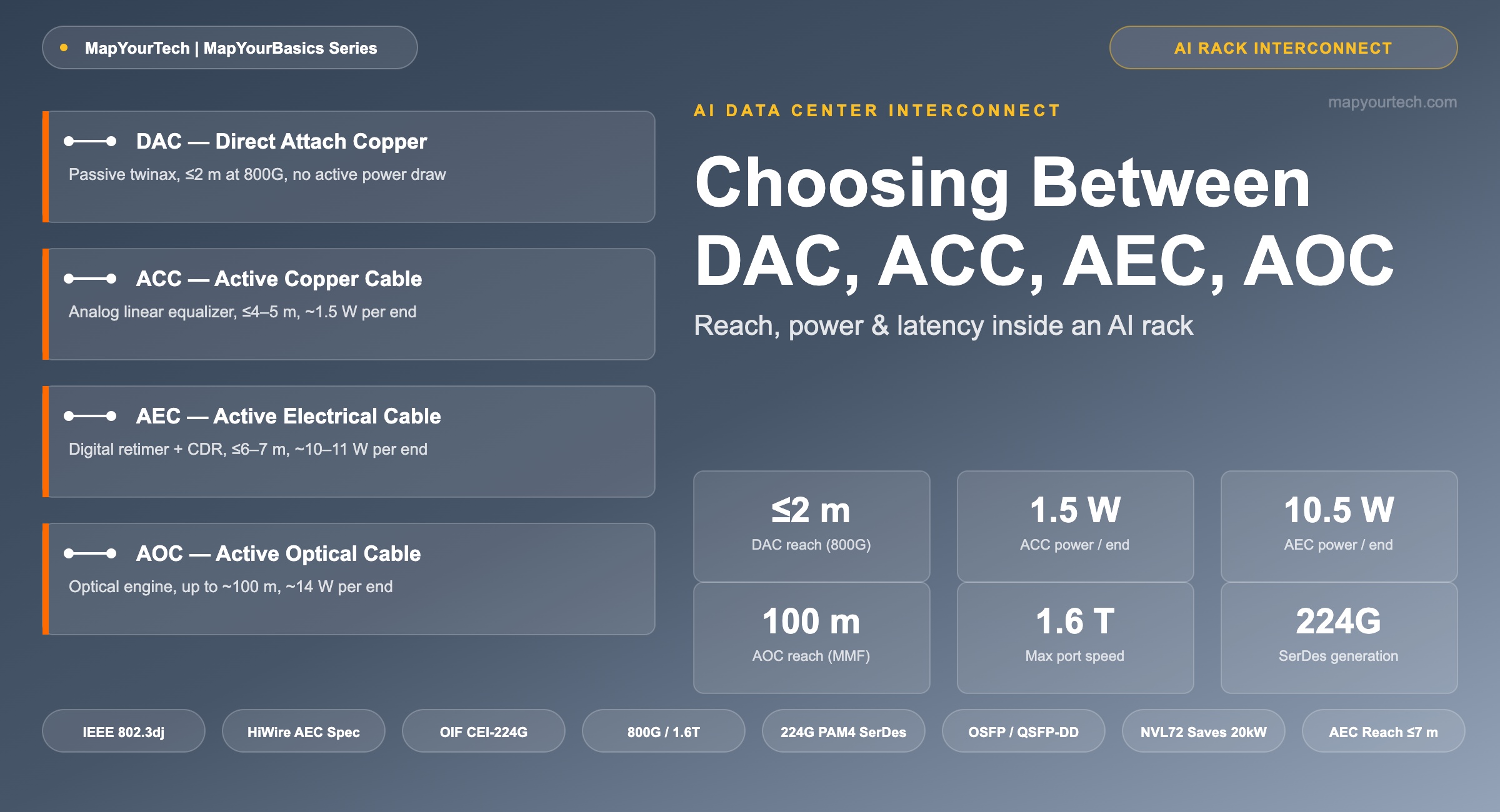
Choosing Between DAC, ACC, AEC, and AOC Inside an AI Rack
Reach, power, and latency of direct-attach copper, active copper, active electrical, and active optical cables — and where each one belongs between a GPU, a switch, and the next rack.
1. Introduction
A GPU cluster spends as much engineering effort moving bits between accelerators as it does computing on them. Inside a single AI rack, thousands of high-speed lanes connect GPUs to NVSwitches or Ethernet leaf switches, and every one of those lanes ends in a cable. At 800G and 1.6T port speeds, the choice of that cable is no longer a cabling-closet decision — it is a power, thermal, and reliability decision that shows up directly in a rack's kilowatt budget.
Four cable families cover the reach range inside and just outside a rack: Direct Attach Copper (DAC), Active Copper Cable (ACC), Active Electrical Cable (AEC), and Active Optical Cable (AOC). All four connect into the same OSFP and QSFP-DD pluggable cages used by transceivers, but they trade signal conditioning, reach, and power against each other in very different ways. A passive DAC costs the least power; a retimed AEC reaches the farthest a copper cable can go; an AOC trades copper's power advantage for a reach that copper cannot match at all.
This article works through what each cable type does electrically or optically inside the connector, the physical reason copper reach shrinks as SerDes rates climb, and a practical framework for deciding which cable belongs on which link inside a 2026-era AI rack.
2. Four Ways to Move a Signal a Few Meters
All four cable types share the same job: carry a PAM4 electrical signal, or an equivalent optical signal, from one host ASIC's SerDes to another's, inside a connector that plugs into a standard OSFP or QSFP-DD cage. What separates them is how much electrical or optical conditioning happens inside the cable assembly itself.
Direct Attach Copper (DAC)
A DAC is a passive twinaxial cable assembly — a bundle of shielded copper pairs soldered directly to connectors at each end, with no active components anywhere in the path. Every source of loss along the channel — conductor resistance, dielectric absorption, connector mismatch — is left uncorrected inside the cable, so the host ASIC's own transmit and receive equalization has to close the entire link budget. Vendor datasheets typically specify a maximum reach of 2 meters for 800G-class passive DAC assemblies using 112 Gbaud PAM4 lanes, down from roughly 3 meters at 400G — this is a vendor-typical figure, and it is the shortest reach of the four cable types by design.
Active Copper Cable (ACC)
An ACC adds an analog linear equalizer — commonly described as a redriver or a continuous-time linear equalizer (CTLE) — inside the connector housing at each end. The equalizer boosts the received signal's amplitude and partially compensates for high-frequency roll-off, but it amplifies noise along with the signal rather than removing it, and it performs no clock or data recovery. That keeps the added latency and power very low: 800G-class ACC assemblies are commonly specified around 1.5 W per end, extending reach to roughly 4–5 meters. At 1.6T port speeds using 224 Gbaud PAM4 lanes, Marvell has stated that a 1.6T ACC can operate at approximately 2.5 W, a vendor-claimed figure reflecting the newer SerDes generation.
Active Electrical Cable (AEC)
An AEC goes a step further and embeds a digital retimer with full clock and data recovery (CDR) at each end. Rather than simply amplifying whatever arrives, the retimer samples the incoming signal, reconstructs clean data, and re-transmits a fresh, jitter-free waveform on the line side. That reconstruction is what lets an AEC push reach out to roughly 6–7 meters at 800G, at the cost of materially higher power — vendor datasheets commonly show around 10–11 W per end for 800G AEC assemblies. The Distributed Disaggregated Chassis (DDC) architectures that some hyperscalers use for scale-up switch fabrics depend on AEC reach to span between chassis elements that a passive DAC could never cover.
Active Optical Cable (AOC)
An AOC replaces copper entirely for the run between connectors. Each end contains a full optical engine — laser, photodiode, and typically a CDR or DSP stage — permanently spliced to a length of multimode or single-mode fiber, all sealed inside a standard electrical connector so the host system sees the same interface it would see from a DAC. Because light in fiber does not suffer the frequency-dependent attenuation that copper does, AOC reach is set by the optics and the fiber grade rather than by conductor loss — commonly out to 100 meters over multimode fiber — but that reach comes at a materially higher power draw than any copper option, typically around 14 W per end at 800G, vendor-typical.
All four share the same electrical interface standard on the host side. The SerDes generation behind them has moved from 106.25 Gbaud PAM4 ("112G" per-lane, 8 lanes = 800G) to 224 Gbaud PAM4 ("224G" per-lane, 8 lanes = 1.6T), and the industry-wide push toward lower power per bit is exactly why the linear, DSP-free options — ACC and, at the module level, Linear Pluggable Optics — have become attractive for the shortest links inside a rack.
3. Inside the Cable: Architecture and Reach
The figure below lays out the signal path for each cable type side by side. Reading left to right, a host ASIC drives its SerDes into the connector; what happens between the two connectors is the entire difference between the four technologies.
Why copper reach shrinks as baud rate rises
The reach gap between DAC, ACC, and AEC is not arbitrary — it follows directly from how copper loses signal energy at high frequency. Above roughly 25 GBd, a twinaxial pair's insertion loss is dominated by conductor loss from the skin effect, where current crowds toward the surface of the conductor as frequency rises, shrinking the effective cross-section the current can use.
Theoretical relationship — skin-effect conductor loss
αskin(f) ∝ √f × L
Where: αskin = conductor attenuation (dB); f = signal frequency near the PAM4 Nyquist point (Hz); L = cable length (m).
Practical Example — Doubling the SerDes baud rate from 106.25 GBd (800G-class, "112G" lanes) to roughly 212 GBd (1.6T-class, "224G" lanes) roughly doubles the relevant Nyquist frequency. Because attenuation scales with the square root of frequency, per-meter loss rises by a factor near √2 (about 41%) at a fixed length — the physical reason passive DAC reach contracts from about 3 m at 400G to roughly 1–2 m at 800G and beyond, and why every SerDes generation pushes ACC and AEC further up the power-reach curve to hold the same physical distance.
That same relationship is why standards and consortia keep the shortest, cheapest option — the passive DAC — but layer active conditioning on top of it rather than trying to redesign copper itself. DSP and retimer silicon supplies the correction that the copper medium cannot provide passively, at the cost of power and a small amount of latency.
Standards and specifications in force
IEEE 802.3dj defines the 200 Gb/s-per-lane electrical and optical PHYs that make 1.6T ports possible — eight lanes of 200 Gb/s PAM4 signaling, versus the eight lanes of 100 Gb/s PAM4 signaling ("112G") that IEEE 802.3df defined for 800G. As of mid-2026, IEEE 802.3dj remains in IEEE-SA ballot review inside the P802.3dj Task Force, with ratification anticipated later in the year — a standard-specified but still-in-progress reference point worth tracking for any 1.6T deployment plan. AEC implementations are governed less by IEEE directly and more by the HiWire Consortium's Active Electrical Cable specification, which standardizes the retimer, gearbox, and mechanical details on top of the underlying IEEE and MSA electrical interfaces so that AECs from different member vendors interoperate. ACC and DAC assemblies follow the OSFP and QSFP-DD Multi-Source Agreements for their mechanical and electrical interfaces, with per-lane signaling parameters drawn from the Optical Internetworking Forum's Common Electrical Interface (CEI) family — CEI-112G for 800G-class lanes and the CEI-224G generation now defining 1.6T-class lanes.
| Cable type | Signal conditioning | Typical max reach* | Typical power* | Added latency | Best-fit link | Governing spec |
|---|---|---|---|---|---|---|
| DAC | None — passive twinaxial pair | ≤2 m at 800G (≤3 m at 400G) | <1 W (no active power draw) | Near zero (wire propagation only) | GPU-to-NVSwitch, same-rack ToR | IEEE 802.3, OSFP / QSFP-DD MSA |
| ACC | Analog linear equalizer (CTLE / redriver) | ≤4–5 m at 800G | ~1.5 W per end | Very low — no retiming stage | Within-rack, adjacent-rack links | OSFP / QSFP-DD MSA, vendor CMIS |
| AEC | Digital retimer with CDR | ≤6–7 m at 800G | ~10–11 W per end | Low — single retime stage | Rack-to-rack scale-up, DDC fabrics | HiWire Consortium AEC spec |
| AOC | Optical engine (laser, photodiode, CDR) | Up to ~100 m (MMF) | ~14 W per end at 800G | Low to moderate | ToR-to-spine, longer intra-DC runs | IEEE 802.3, InfiniBand Trade Association, SFF |
*Vendor-typical figures at 800G-class port speeds; actual values vary by vendor, SerDes generation, AWG gauge, and connector type. Consult a specific vendor's datasheet for a qualified figure.
Plotting power against reach on the same axes makes the trade-off easier to read at a glance than the table alone.
4. Choosing the Right Cable for Each Link
The four cable types are not competing for the same link — they cover different rungs of a reach ladder, and a well-designed AI rack typically uses more than one of them at once.
- GPU-to-NVSwitch or GPU-to-leaf-switch, same rack, under 2 meters: Passive DAC is the default. There is no signal conditioning to pay power for, and the link budget closes comfortably at this distance.
- Adjacent server-to-ToR or short intra-rack runs beyond DAC's reach, 2–5 meters: ACC extends reach at a small, largely fixed power cost, and its lack of a retiming stage keeps added latency close to zero — a meaningful consideration for latency-sensitive collective operations across a GPU fabric.
- Rack-to-rack links inside a scale-up domain or a disaggregated chassis fabric, 5–7 meters: AEC is the only copper option that reliably closes this distance, and its digital retiming makes multi-vendor mixing of switches and NICs across the link more predictable than an ACC's analog equalization would allow.
- ToR-to-spine or any run beyond roughly 7 meters: AOC or a full optical pluggable transceiver pair becomes the only practical choice, since copper's frequency-dependent loss makes an active copper cable's power cost grow faster than fiber's beyond this range.
Practical Example — NVIDIA GB200 NVL72 copper backplane
NVIDIA's GB200 NVL72 rack-scale system connects 72 Blackwell GPUs through a passive copper NVLink backplane rather than optical cabling for the GPU-to-NVSwitch links inside the rack — over 5,000 copper cable connections across four cartridge assemblies, per NVIDIA's published rack designs. NVIDIA states that choosing copper over optics for this backplane avoids roughly 20 kW of additional power draw per rack that retimers and optical transceivers would otherwise add — a vendor claim, and a concrete illustration of why passive and lightly-conditioned copper dominates the shortest, highest-count links in a modern AI rack even as longer links move to active copper or optical interconnects.
Reach is not the only variable worth weighing. Mixed-vendor environments favor AEC over ACC because a retimed, fully deterministic link behaves the same regardless of which switch or NIC vendor sits at the other end, while an ACC's analog equalization can be sensitive to the exact loss profile of the host board it plugs into. Where power budget is the binding constraint — as it typically is in liquid-cooled, 100+ kW racks — every watt saved by staying on passive or lightly-conditioned copper is a watt of cooling capacity freed up for compute. That same power-per-bit pressure is what is pushing the industry toward co-packaged optics for the switch-side ports that must go optical, since shortening the electrical trace between ASIC and optical engine removes much of the need for the DSP power that a conventional pluggable module carries.
For links that leave the rack entirely — connecting AI clusters across a data center floor or between buildings — none of these four cable types apply; that territory belongs to coherent pluggables such as 800G ZR and ZR+ running over IP-over-DWDM architectures, a different reach and power regime entirely.
Takeaway: Match the cable to the distance, not the other way around. Start every link at the shortest reach that gets the physical layout to work, since every step from DAC to ACC to AEC to AOC adds power for reach the link may not actually need.
5. Summary
DAC, ACC, AEC, and AOC form a single reach-power ladder inside an AI rack, each rung adding a specific piece of electrical or optical hardware — a linear equalizer, a digital retimer, or a full optical engine — to buy additional meters at a predictable power cost. Passive DAC still covers the shortest, highest-count links at essentially zero active power; ACC and AEC extend copper's reach into the rack-to-rack range that 800G and 1.6T SerDes rates would otherwise put out of copper's practical range entirely; AOC picks up everything beyond what copper can carry without an unreasonable power penalty. As 1.6T ports built on 224 Gbaud PAM4 lanes move from early deployment toward volume in the back half of 2026, this same ladder holds — each generation simply compresses copper's reach a little further and pushes the crossover to optics slightly closer to the rack.
6. References
- IEEE 802.3dj Task Force — 200 Gb/s, 400 Gb/s, 800 Gb/s, and 1.6 Tb/s Ethernet, IEEE Standards Association.
- HiWire Consortium — Active Electrical Cable (AEC) Specification, HiWire Consortium, hosted via the Open Compute Project.
- Optical Internetworking Forum — Common Electrical I/O (CEI) Implementation Agreements, Optical Internetworking Forum.
Sanjay Yadav, "Optical Network Communications: An Engineer's Perspective" – Bridge the Gap Between Theory and Practice in Optical Networking.
Related Articles on MapYourTech




Continue Reading This Article
Sign in with a free account to unlock the full article and access the complete MapYourTech knowledge base.


