
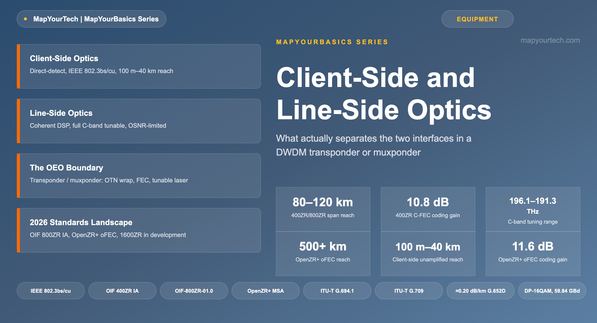
Client-Side and Line-Side Optics: What Separates Them
Why a 400G port on a router and a 400G port on a DWDM line system speak two different optical languages — and what that distinction still means for interoperability in 2026.
1. Introduction
A router's 400G port and a line system's 400G port can share the same QSFP-DD cage, the same duplex LC connector, and the same nominal data rate — and still run on completely different physics. One drives a single wavelength down a two-meter jumper into a mux/demux shelf. The other tunes across the full C-band and rides an amplified fiber span for 80 km or more before the next amplifier touches it. The industry calls the first a client-side interface and the second a line-side interface, and the distinction is not cosmetic. It sets the detection method, the modulation format, the standards body that governs the port, and whether that port can sit behind a reconfigurable optical add/drop multiplexer (ROADM) at all.
This article works through what actually separates the two interfaces inside a transponder or muxponder, how a signal crosses the electrical-to-optical boundary between them, the power-budget and OSNR mechanics that make line-side engineering a different discipline from client-side engineering, and why the split still matters in 2026 even as pluggable coherent optics fold both functions into a single router-hosted module.
2. Two Interfaces, One Wavelength: Defining Client-Side and Line-Side
A client-side interface faces the equipment that generates the traffic — a router, a switch, a SONET/SDH add-drop multiplexer, a storage array running Fibre Channel. It terminates one client signal in whatever native format that equipment produces: 100GbE, 400GbE, OTU4, or 32G Fibre Channel among others. The optics on this side are almost always direct-detection: a laser turns bits into optical power levels, a photodiode converts power back into bits, and there is no local oscillator, no phase recovery, and — critically — no dependence on optical signal-to-noise ratio (OSNR) as a performance metric. IEEE 802.3 governs most of these ports through amendments such as 802.3bs and 802.3cu, which define reach classes from roughly 100 meters to 40 kilometers over point-to-point fiber with no optical amplification anywhere in the path.
A line-side interface faces the opposite direction — toward the DWDM network itself. It carries a wavelength that has already been aggregated, wrapped in Optical Transport Network (OTN) overhead per ITU-T G.709, and protected with forward error correction (FEC). That wavelength has to survive a mux/demux stage, an erbium-doped fiber amplifier (EDFA) or Raman amplifier, an outside-plant fiber span, and — in most metro and long-haul builds — one or more ROADM nodes before it reaches a matching line-side receiver. Coherent detection is what makes that survival possible: a local oscillator laser mixes with the incoming signal in an optical hybrid, and a digital signal processor (DSP) recovers phase and polarization information that direct detection simply discards. That extra information is what lets a line-side receiver compensate for chromatic dispersion, polarization-mode dispersion, and the accumulated noise of every amplifier in the path. The full engineering comparison between the two detection methods, including how far PAM4 direct-detect now reaches into territory coherent once owned alone, is worked through in the MapYourTech guide to coherent versus direct-detect transceiver selection.
A transponder is the device that sits at this boundary. It performs the electrical-to-optical (E/O) and optical-to-electrical (O/E) conversion for one client signal, mapping it into a line-side wavelength. A muxponder does the same job for several client signals at once, using time-division multiplexing on the electrical side to aggregate — for example — four 100GbE clients into a single 400G line-side wavelength. A transponder is really a muxponder with a 1:1 aggregation ratio rather than a separate category of device. The full walkthrough of that distinction, including where each device fits into a metro build, is in the MapYourTech guide to transponders versus muxponders.
Neither side needs to know much about the other. The client-side optic only has to match the host port's electrical interface and the reach to the next piece of client equipment. The line-side optic only has to match the wavelength grid, the amplifier chain, and the FEC scheme running on that DWDM system. That separation of concerns is exactly why the two interfaces evolved under different standards bodies — and why conflating them during a design review is one of the more common ways an engineer discovers, too late, that a port they specified will not do what they assumed.
Takeaway: Client-side asks what protocol a signal carries; line-side asks what wavelength it will occupy. Detection method, standards body, reach, and amplifier compatibility all follow from that one distinction.
3. Architecture, Parameters, and the Power Budget
Figure 1 traces a signal from the client port to the outside plant. Four direct-detect client ports — a mix of SR8, DR4, FR4, and LR4 optics in this example — feed a transponder or muxponder. Inside that box, each client signal is terminated electrically, mapped into an OPU/ODU/OTU frame per ITU-T G.709, and combined with the others if the box is operating as a muxponder rather than a straight transponder. The framer adds FEC overhead, and a tunable laser under DSP control generates the single line-side wavelength that carries the aggregated payload.
That wavelength leaves the transponder through a coherent line-side port and enters the optical line system: a wavelength-selective switch (WSS) or arrayed-waveguide grating (AWG) multiplexes it with other channels onto the shared fiber, an EDFA booster amplifier raises the composite signal to a launch power the fiber span can tolerate, and the outside-plant fiber carries it to the next ROADM node or amplifier site. The general signal-flow sequence, including how the optical multiplex section (OMS) and optical channel (OCh) layers stack on top of each other, is covered in more depth in the MapYourTech primer on general optical signal flow, and the add/drop mechanics a line-side wavelength depends on once it reaches a switching node are covered in the guide to OpenROADM architecture.
| Parameter | Client-Side | Line-Side |
|---|---|---|
| Detection method | Direct detection (IM/DD) | Coherent detection (DSP + local oscillator) |
| Modulation | NRZ / PAM4 | DP-QPSK, DP-8QAM, DP-16QAM |
| Governing standards | IEEE 802.3 (802.3bs, 802.3cu), 100G Lambda MSA | OIF 400ZR/800ZR IA, OpenZR+ MSA, ITU-T G.709 |
| Typical unamplified reach | 100 m – 40 km (SR8 to ER8 class) | Not applicable — always amplified |
| Typical amplified reach | Not applicable | 80–120 km per span (400ZR/800ZR); 500+ km with OpenZR+ oFEC |
| Wavelength assignment | Fixed CWDM lanes (O-band, approx. 1271–1331 nm) or single wavelength | Full C-band, ITU-T G.694.1 grid, 196.1–191.3 THz |
| FEC | Host-side RS(544,514) KP4 (IEEE) | C-FEC (approx. 10.8 dB NCG, 400ZR) or oFEC (approx. 11.1–11.6 dB NCG, OpenZR+/800ZR) |
| OSNR dependence | No — power-budget limited | Yes — OSNR-budget limited across amplified spans |
| ROADM/WSS compatibility | No — fixed wavelength, not grid-tunable | Yes — full C-band tunable for add/drop routing |
| Typical form factors | QSFP-DD, QSFP28, SFP-DD | QSFP-DD, OSFP, CFP2-DCO |
Why the Power Budget Behaves Differently on Each Side
A client-side link is engineered against a straightforward power budget: the transmitter's launch power minus the receiver's sensitivity has to exceed the total loss in the fiber path, with margin left over for connectors, splices, and aging.
Optical Power Budget
Must satisfy: Pbudget ≥ (α × L) + Lconnectors + Lmargin
- Ptx = transmitter launch power (dBm)
- Prx,sensitivity = minimum receiver input power for the target bit-error rate (dBm)
- α = fiber attenuation coefficient (dB/km)
- L = span length (km)
- Lconnectors = cumulative connector and splice loss (dB)
- Lmargin = design margin for aging and repair splices (dB)
Practical Example — Line-Side 80 km Amplified Span:
Fiber attenuation α ≈ 0.20 dB/km, a typical measured value for modern G.652D single-mode fiber at 1550 nm. Over L = 80 km that alone accounts for 16.0 dB of loss. Add a typical connector and patch-panel allowance of about 6 dB and an aging/repair margin of about 3 dB, and total link loss lands near 25 dB.
A coherent line-side transceiver launching near 0 dBm — within the −10 to +4 dBm typical range published for modern coherent line-side modules — and closing on a receiver with roughly −14 dBm typical sensitivity has about 14 dB of passive budget. That is roughly 11 dB short of the 25 dB the span requires, which is exactly the gap a booster and pre-amplifier EDFA close.
Because a client-side link is unamplified and short, its budget is usually generous — several dB to spare even near maximum reach. A line-side link is a different problem, as the example above shows: the fiber and connector losses on an 80 km amplified span routinely exceed what raw launch power and receiver sensitivity can close on their own, which is why every amplified DWDM span carries a booster amplifier, an in-line amplifier, or both.
Once an amplifier sits in the path, the limiting parameter stops being power and becomes OSNR. Every EDFA adds amplified spontaneous emission (ASE) noise on top of the signal it boosts, and that noise accumulates span over span in a cascaded line system. A client-side link never faces this problem, because it has no amplifiers to accumulate noise from — power budget alone tells the whole story. A line-side link can have plenty of power left over and still fail if accumulated OSNR falls below what the coherent receiver's modulation format requires; 16QAM demands a materially higher OSNR floor than QPSK for the same bit-error-rate target. The mechanics of that trade-off, including how baud rate and channel bandwidth interact with the Shannon limit, are worked through with a live calculator in the MapYourTech guide to link design and the Shannon limit, and the full parameter set a link-engineering report has to track is catalogued in the MapYourTech basics of DWDM link design.
4. Interoperability in 2026
The client-side/line-side split used to map cleanly onto physical boxes: client optics in the router, a transponder shelf in the middle, line-side optics facing the fiber. Pluggable coherent optics have been eroding that mapping since the OIF published the original 400ZR Implementation Agreement, and the trend continued through 2026. A 400ZR or OpenZR+ module in QSFP-DD or OSFP form factor now plugs directly into a router or switch faceplate and performs both functions in one piece of hardware: it presents a standard Ethernet host interface to the router's network processor while generating a fully tunable, coherent line-side wavelength on its fiber-facing side. The transponder shelf disappears, but the functional distinction between client-side behavior and line-side behavior does not — it just moves inside a single module. That architecture, and the power savings that come from collapsing three optical-electrical conversions into one, is covered in the MapYourTech walkthrough of IP-over-DWDM architecture and the related power-per-bit analysis of router optics.
The standards landscape kept moving in 2026. The OIF's 800ZR Implementation Agreement — covering single-span, amplified 80–120 km links for data-center interconnect at up to 800G aggregate bandwidth — has been shipping alongside further updates to the 400ZR IA, and the OIF used OFC 2026 in Los Angeles to run a multivendor interoperability demonstration with roughly 40 member companies validating the next generation of building blocks, including early 1600ZR-class specifications the organization has in development for data-center and campus applications. The OpenZR+ MSA continues to serve the segment 400ZR was never meant to reach: its oFEC coding gain, noticeably higher than 400ZR's concatenated FEC, extends usable reach well past 500 km in lower-order modulation modes — the reason a carrier network and a hyperscale DCI network rarely standardize on the same line-side module even when both run coherent 400G.
Two practical rules follow. On the client side, match the PMD to the actual physical reach rather than defaulting to the longest-reach option available — an LR4 module costs more and draws more power than a DR4 or FR4 for a link that will never need 10 km of fiber, and the MapYourTech guide to optical reach classifications lays out the full SR/DR/FR/LR/ER ladder for that decision. On the line side, match the DCO configuration — 400ZR, OpenZR+, or an OTN-framed embedded transponder — to the actual span budget and OSNR requirement of the route, not to whichever module is cheapest per port; a module that closes the power budget on paper can still fail in service if its OSNR margin does not survive the number of amplified spans the wavelength actually crosses.
5. Summary
Client-side and line-side describe two different jobs, not two different quality tiers. A client-side port exists to speak the exact protocol the attached equipment already uses, over a reach short enough that direct detection and a simple power budget are all the engineering the link needs. A line-side port exists to survive an amplified, multi-span DWDM network, and that survival demands coherent detection, DSP-based impairment compensation, and an OSNR budget that a power-budget calculation alone cannot capture. Pluggable coherent optics have merged the two functions into single modules that live in router faceplates, and the OIF's 2026 work on 800ZR and early 1600ZR-class specifications is pushing that convergence further up the capacity curve. What has not changed, and will not change as long as fiber attenuates and amplifiers add noise, is the underlying split: one interface is built to talk to the equipment next to it, and the other is built to survive the network in between.
Takeaway: When a design review turns on whether an optic will work in a given slot, ask which job it is doing — talking to adjacent equipment, or surviving the amplified network — before comparing data sheets. The answer determines the detection method, the standards body, and the power budget that actually applies.
References
- OIF-800ZR-01.0 — Implementation Agreement for 800ZR Coherent Interfaces, Optical Internetworking Forum.
- ITU-T G.694.1 — Spectral Grids for WDM Applications: DWDM Frequency Grid, ITU-T Study Group 15.
- IEEE 802.3 (802.3bs and 802.3cu amendments) — Standard for Ethernet, Physical Layer Specifications and Management Parameters for 100 Gb/s and 400 Gb/s Operation, IEEE 802.3 Working Group.
- Sanjay Yadav, "Optical Network Communications: An Engineer's Perspective" – Bridge the Gap Between Theory and Practice in Optical Networking.
Related Articles on MapYourTech






