
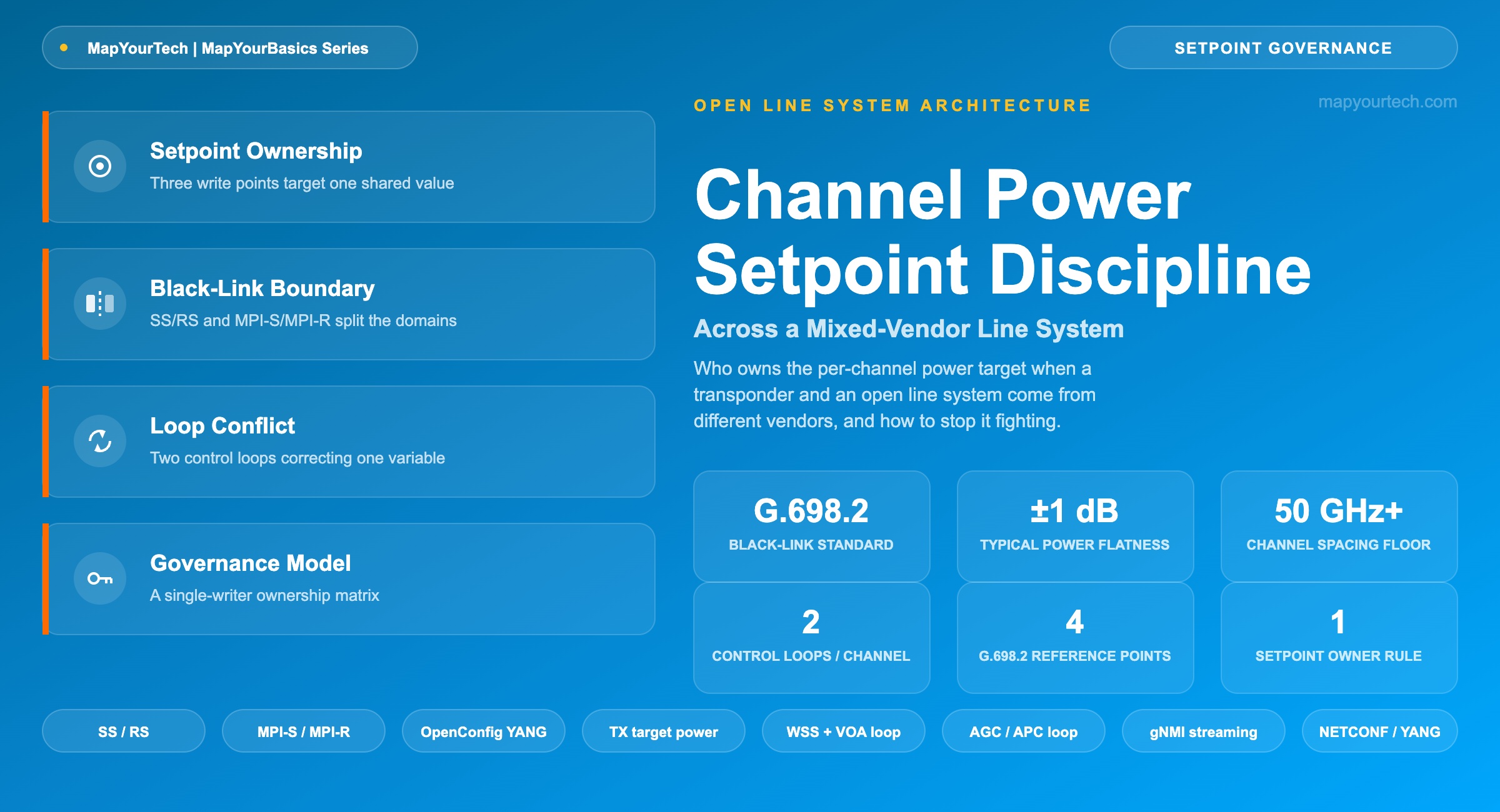
Channel Power Setpoint Discipline Across a Mixed-Vendor Line System
Who owns the per-channel power target when the transponder and the line system come from different vendors, and the governance that keeps their control loops from correcting against each other.
Introduction
A channel power setpoint is a single number, expressed in dBm, that every control system touching a wavelength on a line system is quietly trying to hit. On a single-vendor system, one supplier writes that number once and the argument never happens. On a mixed-vendor line system — a coherent transponder from one vendor riding an open line system (OLS) built by another — two separate control loops can each hold a legitimate, standards-compliant claim to the same variable. Unless someone has written down which loop wins, they correct against each other indefinitely.
This article defines the setpoint precisely, locates the standard-specified boundary where transponder ownership ends and line-system ownership begins, explains the mechanism by which two independent loops fight over one physical quantity, and lays out a governance model — a single-writer ownership matrix — that closes the gap the standards leave open.
1. What a Channel Power Setpoint Is, and Why It Needs an Owner
A per-channel power setpoint (Pch,target) is the design value, in dBm, that a wavelength's optical power is supposed to hold at a defined point in the network — most often the line-system add port, immediately after the reconfigurable optical add/drop multiplexer's (ROADM) wavelength-selective switch (WSS). It is not a single measurement; it is a target that three independent subsystems can each try to enforce: the transponder's transmit (TX) laser and its automatic power control (APC) loop, the ROADM add-port's per-channel variable optical attenuator (VOA), and the booster erbium-doped fiber amplifier's (EDFA) gain or output-power control loop.
Each of those three has a legitimate reason to hold an opinion about the number. The transponder cares because its receiver-side digital signal processor (DSP) budgets optical signal-to-noise ratio (OSNR) against reach starting from a known launch power. The ROADM cares because per-channel gain equalization keeps every wavelength inside the amplifier's linear operating region and stops one bright channel from starving its neighbors through gain competition. The booster EDFA cares because its own control loop — running in constant-gain or constant-output-power mode — sets the aggregate power budget that the per-channel VOA profile has to fit inside.
A common line-system design guideline holds per-channel power flatness to about ±1 dB across the operating band — a typical target that varies by platform, not a fixed standard value, since the tolerance a given system publishes depends on its amplifier gain ripple and WSS insertion-loss uniformity. Inside that band, a correction step from one control loop is statistically indistinguishable from measurement noise to any other loop watching the same channel. That is the crack two independent loops fall into.
Formula — Per-Channel Power Budget at the Line-System Add Port
PMPI-S = PTX − ILmux − ILpatch

Where:
  P(MPI-S)  = channel power at the multichannel physical interface,
              source side (MPI-S), dBm
  P(TX)     = transponder transmit output power, dBm
  IL(mux)   = insertion loss of the add multiplexer / WSS stage, dB
              (typical range: 5-7 dB for a WSS-based add stage)
  IL(patch) = insertion loss of patch cords and connectors
              between transponder and line system, dB

Example:  P(TX) = 0 dBm, IL(mux) = 6 dB, IL(patch) = 1 dB
          P(MPI-S) = 0 − 6 − 1 = −7 dBm

This is the power arriving at the line system's own VOA and booster
stage before either applies its own correction toward the published
per-channel design target.
IL(mux) range is a typical WSS/ROADM insertion-loss figure, not a value fixed by any single standard; confirm against the specific line-system platform's datasheet.
Takeaway: A channel power setpoint is a shared variable with three physically distinct write points — transponder TX, ROADM VOA, and booster EDFA — and by default none of them knows the other two exist.
2. The Black-Link Boundary: Where G.698.2 Draws the Line
ITU-T G.698.2, approved in November 2018, is the standard that names this exact problem and draws a line down its middle. Its scope defines single-channel optical interface parameters for amplified multichannel dense wavelength-division multiplexing (DWDM) systems using a "black link" approach — a model in which the line system between two reference points is treated as an opaque optical path with published input and output parameters, so that transponders from one vendor can operate across a line system built by another. The recommendation states its motivation directly: these single-channel interfaces exist to eliminate the transponders that would otherwise be required to make multivendor DWDM networks interoperate.
G.698.2 fixes four reference points. SS and RS sit at the transponder-facing single-channel boundary — the point where one vendor's laser output or receiver input is specified independent of what sits on the other side of the black link. MPI-S and MPI-R sit at the multichannel, amplified boundary — the aggregate optical interface where the line system's per-channel and total power parameters are specified, at a channel frequency spacing of 50 GHz or wider. For a transponder plugging into an open line system, SS and MPI-S are, in practice, the same physical point: the line system's add port.
| Reference Point | Location | What It Fixes |
|---|---|---|
| SS | Transponder-facing single-channel input to the black link | Single-channel optical interface parameters (power, OSNR, dispersion tolerance) |
| RS | Transponder-facing single-channel output from the black link | Single-channel optical interface parameters at the receive side |
| MPI-S | Multichannel, amplified boundary — line-system input | Aggregate and per-channel power parameters at 50 GHz spacing and wider |
| MPI-R | Multichannel, amplified boundary — line-system output | Aggregate and per-channel power parameters at the receive boundary |
What G.698.2 does not do is assign a control-loop owner to that point. The standard specifies static optical parameters that both sides must meet at the reference point — it says nothing about which side's control loop is allowed to actively adjust power there once the link is in service. That silence is not an oversight; a physical-layer interface standard is the wrong place to specify operational control-plane behavior. But it means every operator running a mixed-vendor OLS inherits a governance decision the standard deliberately left unmade.
Takeaway: G.698.2 tells both vendors what the number at MPI-S/SS has to be. It does not tell either vendor's control loop who is allowed to move it.
3. Two Control Loops, One Variable — the Fight
The mechanism is ordinary control theory applied to a boundary nobody assigned. Loop A lives in the transponder: many coherent modules expose a target-output-power leaf in the OpenConfig terminal-device model — the YANG model originally intended to provision external optical transponders, implemented by vendors including Cisco for platforms such as the NCS 1004 muxponder, and configurable over NETCONF or gNMI. When that leaf stays writable during live operation, and the transponder's firmware adjusts TX power in response to received OSNR telemetry or a link-margin target, Loop A is actively correcting the same channel power the line system also claims.
Loop B lives in the line system: the openconfig-optical-amplifier model exposes gain, output power, and mode of operation for EDFAs deployed as part of the transport line system, and the ROADM's per-channel VOA profile is driven by an optical channel monitor (OCM) reading against the line system's own equalization target. Loop B does not know or care what value the transponder's firmware last wrote to target-output-power; it only sees the power arriving at its own monitor point and corrects toward its own reference.
Neither loop is malfunctioning. Each is executing a valid control algorithm against a valid local target. The failure mode appears when the two targets are not numerically identical — even a few tenths of a decibel is enough — or when both loops sample and correct within overlapping time windows, so that Loop B's correction to VOA attenuation changes the power Loop A's monitor reads, prompting a further TX adjustment, which changes the power Loop B's OCM reads on the next cycle. The result is sustained hunting: a slow oscillation in per-channel power that never settles, most visible during channel turn-up and immediately after traffic churn, when adding or dropping neighboring channels produces a transient power excursion that gives both loops something to react to at the same moment. This is also where mixed channel-rate loading compounds the problem, since a fast-settling loop on one channel can still be reacting to a slower neighbor's transient. Some C+L band line systems address exactly this scenario with orchestrated, software-sequenced turn-up and turn-down of traffic channels, specifically to control the order in which each loop is allowed to act — a vendor-implemented operational practice, not a standards requirement, that exists because the standards do not settle the ownership question on their own.
Takeaway: Two loops converging on the same channel power from different reference points and different measurement taps do not need to disagree by much — a few tenths of a decibel and overlapping correction timing are enough to produce sustained hunting instead of convergence.
4. Building a Setpoint Ownership Model That Holds
The fix is not a smarter control loop on either side; it is a single-writer rule enforced at the operational layer, since neither G.698.2 nor either vendor's YANG model enforces it for you. One domain gets write authority over the power at the shared reference point; the other domain is limited to read-only telemetry once the channel is in service.
In the ownership model most mixed-vendor OLS deployments converge on, the line system holds write authority over per-channel power at MPI-S/MPI-R, because it is the only domain with visibility into every channel sharing the amplifier chain — a transponder can see its own wavelength but not the neighbors competing for the same erbium gain. The transponder's target-output-power is set once during turn-up to match the line system's published add-port window, then locked: any adaptive TX-power steering the transponder firmware supports gets disabled or fixed to a static value for that channel, so the only active loop touching launch power past turn-up is the line system's WSS/VOA equalization loop. The transponder keeps writing everything on its own side of SS — modulation format, baud rate, forward error correction (FEC) mode — and keeps reading OSNR and received-power telemetry, but it stops writing power once the channel is live. This division of authority is the same pattern used across a well-run IP-over-DWDM signal path: the OLS commissions the optical layer before a wavelength carries traffic, and the client-facing equipment inherits that window rather than renegotiating it.
| Parameter | Reference Point | Owner (Write Authority) | Transponder Role |
|---|---|---|---|
| Per-channel launch power (Pch) | MPI-S / SS | Open line system — WSS/VOA equalization loop | Read-only telemetry after turn-up |
| Transponder TX output power | SS | Transponder — fixed at turn-up | Set once to match the published add-port window |
| Booster EDFA gain / output power | Line-system amplifier stage | Open line system — AGC/APC loop | No visibility required |
| Per-channel equalization target profile | MPI-S (multichannel) | Line-system controller (NETCONF/YANG) | Consumes the published target as reference only |
| Received power at pre-amplifier | MPI-R | Open line system — monitoring | Reports OSNR/BER; does not request TX changes |
This is the same single-writer principle that keeps two DHCP servers from handing out the same IP address, applied to an analog quantity instead of a discrete one. The precedence has to be explicit in the turn-up procedure and in the NETCONF/YANG configuration pushed to both domains — not left to firmware defaults, which vary by vendor and by software release. A multivendor link-planning workflow that already tracks each vendor's launch-power window as a design input is the natural place to record which domain owns the live setpoint, so the governance decision does not get rediscovered at every turn-up.
Takeaway: One domain writes the shared setpoint; the other reads it. Which domain writes is a governance decision the operator has to make explicitly, because neither the black-link standard nor either vendor's default firmware makes it for you.
5. Verifying the Boundary in Live Telemetry
Practical Example — Turn-up validation on a mixed-vendor segment. An operator brings up a new coherent channel across a transponder from one vendor and an open line system from another. During the settling window after the channel is added, the commissioning procedure polls two things: the line system's OCM reading at MPI-S against its published tolerance window, and the transponder's target-output-power telemetry. A converged setup shows the OCM reading settle inside the tolerance band while the transponder's reported TX power stays flat — evidence that only one loop moved. A fighting setup shows the transponder's TX power telemetry stepping up and down in a pattern that mirrors the OCM readings' correction history — evidence that Loop A is still live and contesting the setpoint.
Streaming telemetry over gNMI, rather than periodic NETCONF polling, catches this pattern earlier because the sample rate is high enough to resolve the correction cycle instead of aliasing it into what looks like ordinary noise. A 2026 benchmarking study comparing gNMI streaming telemetry against NETCONF polling in OpenConfig- and OpenROADM-driven optical control reported meaningfully lower controller CPU load and shorter telemetry latency for the gNMI path under its test conditions — a measured result specific to that benchmark, not a universal guarantee, but it illustrates why the industry's monitoring stack is moving toward streaming telemetry for exactly this class of problem.
Takeaway: The tell for a fighting control loop is correlation, not magnitude — a transponder's TX power telemetry moving in lockstep with the line system's equalization corrections, even within the normal tolerance band, is the signature to watch for.
Summary
The setpoint itself was never the hard part; per-channel power budgeting is decades-old engineering. What changed is that disaggregation put two independently sourced, independently firmware-updated control loops on either side of a boundary that a physical-layer standard was never designed to govern. As open line systems carry more vendor combinations, and transponders ship more autonomous power-steering firmware by default, the setpoint ownership question will keep surfacing at every multivendor turn-up rather than settling once. The operators who avoid it are the ones who write the ownership matrix down before the first channel goes live, not the ones who debug a slow oscillation months into service and discover two loops that never knew about each other.
References
- ITU-T G.698.2 — Amplified Multichannel Dense Wavelength Division Multiplexing Applications with Single Channel Optical Interfaces, ITU-T Study Group 15.
- ITU-T G.694.1 — Spectral Grids for WDM Applications: DWDM Frequency Grid, ITU-T Study Group 15.
- OpenConfig — Terminal Device and Optical Amplifier YANG Models, OpenConfig Working Group.
Sanjay Yadav, "Optical Network Communications: An Engineer's Perspective" – Bridge the Gap Between Theory and Practice in Optical Networking.
Related Articles on MapYourTech






