
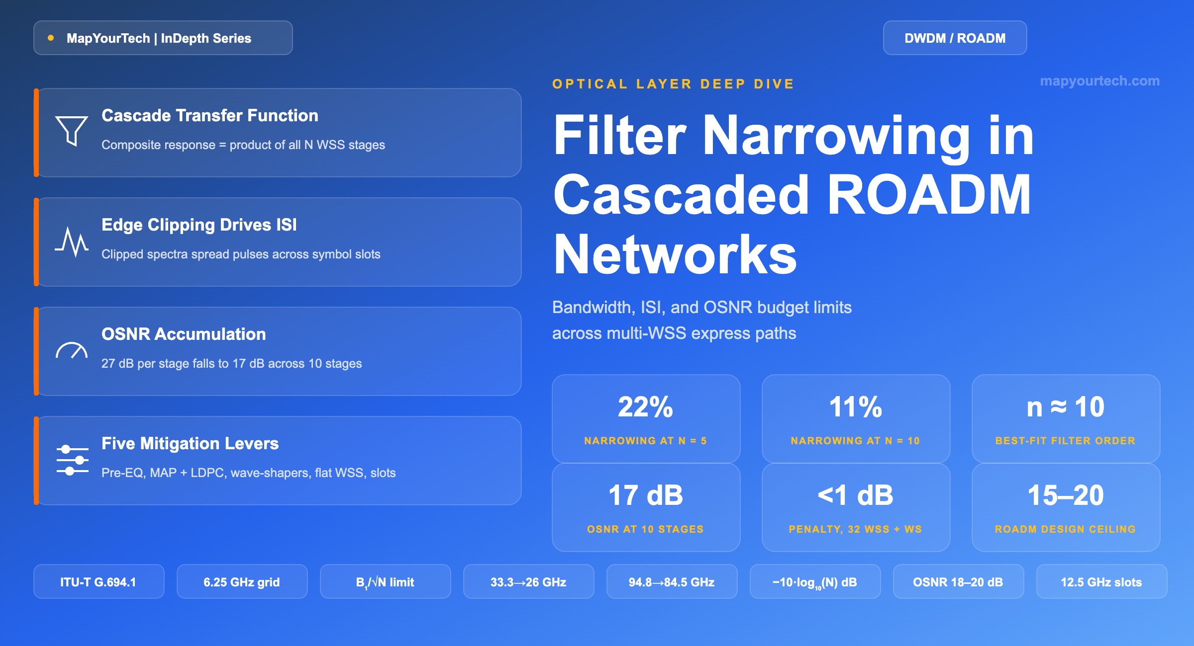
Filter Narrowing in Cascaded ROADM Networks: Bandwidth, ISI, and OSNR Budget Limits
How stacking wavelength selective switches reshapes the optical passband, and the design math that keeps coherent channels inside their error budget.
1. Introduction
A 400G or 800G wavelength crossing a national backbone rarely touches just one reconfigurable optical add-drop multiplexer (ROADM). A typical long-haul or metro-core path threads through six, ten, sometimes twenty express nodes before it reaches a drop port, and at every one of those nodes the signal passes through at least one wavelength selective switch (WSS). Each WSS is a real optical filter with a finite-slope passband, not an ideal brick wall, and the composite response of a chain of filters is the product of every individual response along the path. That multiplication is the entire story behind "filter narrowing," and it is the reason optical layer designers budget for it the same way they budget for fiber loss or chromatic dispersion.
The topic has become more pressing, not less, as the industry has moved from 100G QPSK to 400G and 800G signals built on 16-QAM, probabilistic constellation shaping, and baud rates above 130 Gbaud. Higher-order formats pack more bits per symbol into a smaller signal-to-noise margin, which means they tolerate less amplitude and phase distortion at the channel edges — exactly where a narrowed passband does its damage. At the same time, flex-grid deployments per ITU-T G.694.1 are packing channels closer together to raise fiber capacity, which shrinks the guard band available to absorb any narrowing that does occur.
This article works through the physics of why cascaded WSS filtering narrows the usable passband, derives the transfer-function math behind it, connects that narrowing to intersymbol interference (ISI) in the time domain, and lays out the OSNR, ripple, and crosstalk budget items that a design engineer actually has to track across a multi-ROADM path. It then uses two independently published cascade measurements to back-solve the effective filter order of real WSS hardware — the single number that determines how fast a given network narrows — before closing with the mitigation techniques in production use today and where the 2026 standards landscape is headed as baud rates keep climbing toward 1.6T-class coherent interfaces.
2. Fundamentals: The WSS as an Optical Bandpass Filter
Inside a modern ROADM, the WSS is the component that gives each degree its wavelength-level switching function. Liquid-crystal-on-silicon (LCoS) devices are the dominant switching engine in current-generation WSS modules: a diffraction grating spatially separates the incoming wavelengths, imaging optics focus each wavelength onto a distinct column of the LCoS pixel array, and the array applies a programmable phase pattern that steers each wavelength to its chosen output port. MEMS-based WSS designs use tilting micro-mirrors to perform the same steering with a mechanically simpler but coarser-grained approach; the tradeoff shows up in switching-time and filter-shape flexibility, with WSS-class devices commonly specified under 20 ms switching against under 50 ms for MEMS-class switching in typical DWDM design guidance.
The finite-slope passband follows directly from the physics of this arrangement. The optical field arriving at the LCoS plane is not an infinitely thin line per wavelength — it has a finite spot size set by the grating dispersion and the imaging optics. The filter shape a channel experiences is, to first order, the convolution of that optical spot with the rectangular pixel-boundary pattern programmed on the array. Convolving a rectangle with a finite-width spot always rounds the corners: transmission cannot fall from full power to full rejection over zero frequency. The result is a passband that is flat across most of the channel with a roll-off region at each edge — commonly modeled as a super-Gaussian profile, where a higher filter order means a flatter top and steeper edges. WSS designers deliberately push that order as high as the optics allow, precisely to slow the narrowing effect this article is about.
Read the Full Analysis with Premium
The remaining 88% of this article — the design numbers, trade-offs and field guidance — is part of MapYourTech Premium, along with the full premium library, courses and professional tools.
You May Also Like

-
Free
-
September 4, 2026

-
Premium
-
September 4, 2026

-
Premium
-
September 4, 2026