
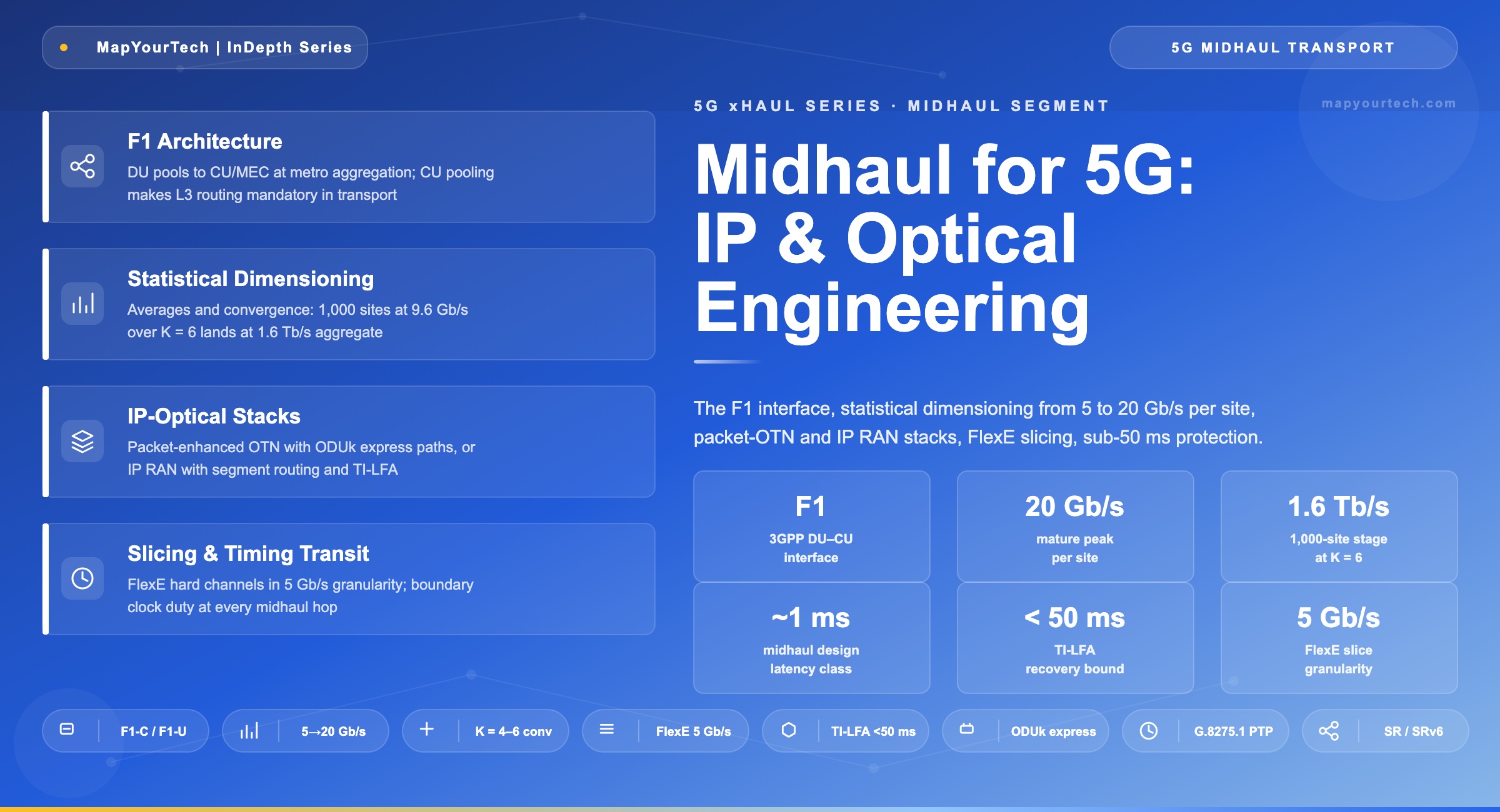
Midhaul for 5G: IP and Optical Network Engineering
Architecture, requirements, and product capabilities for the DU–CU segment: the F1 interface, statistical bandwidth from 5 to 20 Gb/s per site, packet-enhanced OTN and IP RAN stacks, FlexE slicing, and sub-50 ms protection.
1. Introduction
Midhaul is the transport segment between the distributed unit (DU) and the centralized unit (CU), carrying the 3GPP F1 interface, and it did not exist before 5G split the baseband in two. It is the newest segment in the metro and the one most often mis-specified: too many designs treat it as small backhaul, missing that midhaul inherits a routing requirement from CU pooling, a sub-millisecond design class from end-to-end latency targets, and a synchronization-transit duty that ordinary IP aggregation never carries.
The traffic itself is statistical IP, close to user throughput plus F1 protocol overhead: operator planning estimates published in industry white papers put a typical site near 5 Gb/s peak and 3 Gb/s average with early 100 MHz spectrum, growing toward roughly 20 Gb/s peak and 9.6 Gb/s average as millimeter-wave bands mature. Those numbers converge statistically up the aggregation tree, which makes midhaul the first segment where capacity planning looks like classical IP engineering rather than radio provisioning. This article covers the F1 architecture, the requirement set, dimensioning mathematics, the two dominant IP-optical technology stacks, slicing, protection, and a product capability checklist; the segment's position in the full three-segment model is set out in the companion overview of 5G transport network architecture.
Takeaway: Midhaul is statistical IP traffic (5 to 20 Gb/s peak per site across the deployment cycle) under transport-grade constraints: a ~1 ms design class, full timing transit, sub-50 ms protection, and dynamic routing forced by CU pooling. It is neither fronthaul nor small backhaul.
2. Midhaul Architecture: the F1 Segment
2.1 What F1 Connects
The F1 interface joins the DU, which runs the real-time protocol layers for tens of radios, to the CU, which runs Packet Data Convergence Protocol and Radio Resource Control for many DUs from a regional location. F1 splits into a control plane (F1-C) and a user plane (F1-U), both riding IP. The CU's natural home is the metro aggregation site, frequently collocated with multi-access edge computing (MEC), because that placement keeps the F1 reach in the tens of kilometers while putting the CU next to the edge applications it feeds.
CU pooling is the architectural fact that shapes everything else. A DU that can re-home across two or more CU pools for redundancy and load sharing cannot be served by a static circuit: the midhaul must resolve destinations dynamically, which means IP addressing, IP forwarding, and a routing control plane in the transport layer. When an operator instead collocates CU and DU in one gNB, the preferred pattern for ultra-reliable low-latency services, the midhaul segment disappears entirely; segment existence is a deployment decision, and the transport design must accommodate both outcomes, as detailed in the companion OTN architectures that support 5G.
2.2 Physical Topology
Midhaul rides the access and aggregation layers of the metro: DU pool sites feed aggregation rings or trees of packet-optical nodes, which feed the CU/MEC site. North-south traffic dominates; east-west flows exist only between neighboring coordination partners, so simplified aggregation-tree forwarding suffices below the metro core. Ring plant brings shared fiber and built-in protection at the cost of accumulated per-node delay; industry guidance recommends migrating latency-critical layers from ring toward tree topologies, where only source-to-sink hops count against the budget.
Takeaway: Midhaul architecture is fixed by CU placement: the CU lives at the metro aggregation site beside MEC, DU pools re-home across CU pools, and the segment must therefore route, not just transport. Tree topologies beat rings wherever the latency class is tight.
3. Transport Requirements
Midhaul requirements derive from three sources: 3GPP end-to-end latency targets, the radio layer's interruption tolerance, and the statistical nature of post-PDCP traffic. The set below is what a candidate technology stack must satisfy.
Bandwidth is statistical and growing: near 5 Gb/s peak / 3 Gb/s average per site early, toward 20 Gb/s peak / 9.6 Gb/s average at maturity per operator planning estimates, with 4:1 to 6:1 convergence applying upward. Latency is bounded indirectly: 3GPP TR 38.913 sets 4 ms (eMBB) and 0.5 ms (URLLC) end-to-end user-plane targets between terminal and CU, which after radio and processing allocations leaves a midhaul design class around 1 ms and reaches of tens of kilometers. Routing is mandatory because of CU pooling and DU re-homing. Synchronization transit is mandatory because the PTP chain from grandmaster to DU crosses every midhaul hop: each node must be a boundary clock under the full-timing-support profile. Recovery stays under 50 ms. Slice isolation must hold end to end, since URLLC traffic shares the segment with eMBB.
| Requirement | Value | Source / driver | Design consequence |
|---|---|---|---|
| Per-site bandwidth | 5 → 20 Gb/s peak | Operator planning estimates | 25/50GE access links, statistical sizing |
| Latency class | ~1 ms design | 3GPP TR 38.913 end-to-end targets | Tens-of-km reach; hop-count discipline |
| Routing | IP / L3 required | CU pooling, DU re-homing | IGP + SR in the transport layer |
| Timing transit | Boundary clock per hop | ITU-T G.8275.1 full timing support | T-BC class specified in RFP |
| Recovery | < 50 ms | Baseband interruption tolerance | TI-LFA or ODUk SNCP |
| Slice isolation | Hard for URLLC | 5G service classes | FlexE / ODUk channels |
Takeaway: The midhaul requirement set is IP bandwidth plus four transport-grade duties: a ~1 ms latency class, per-hop boundary clocking, sub-50 ms recovery, and hard slice isolation. Any stack that delivers only the bandwidth fails the segment.
4. Bandwidth and Dimensioning
Midhaul dimensioning is bottom-up arithmetic: per-site rates, multiplied by site count, divided by the statistical convergence ratio at each aggregation stage. Convergence applies here because post-PDCP traffic follows users, not radio configuration; busy hours across a metro do not align, and 4:1 to 6:1 ratios between access and core are defensible per operator planning estimates.
Cagg = ( Nsites × Rsite,avg ) / Kconv

Where:
  Nsites    = sites served by the aggregation stage
  Rsite,avg = average per-site midhaul rate (Gb/s)
  Kconv     = statistical convergence ratio (4–6)

Practical Example — aggregation stage at maturity:
  1,000 sites × 9.6 Gb/s / 6 = 1.6 Tb/s
  (operator planning estimates for per-site rates)
The per-site trajectory drives interface selection: 25GE access links carry the early profile with headroom, 50GE covers the mature peak, and 100GE appears at the first aggregation stage where tens of sites combine. The two charts below show the per-site evolution and the convergence effect that keeps aggregate capacity finite.
Figure 2: Per-site midhaul bandwidth, early versus mature deployment, per operator planning estimates published in industry white papers.
Figure 3: Aggregated capacity for 1,000 sites at 9.6 Gb/s average versus convergence ratio (derived from the dimensioning formula above).
Practical Example — sizing one aggregation ring: A ring serves 12 DU-pool sites at the mature profile (20 Gb/s peak, 9.6 Gb/s average each). Worst-case sum is 240 Gb/s, but busy hours do not align: at K = 4 the ring carries 12 × 9.6 / 4 = 28.8 Gb/s sustained, and peak coincidence analysis lands the design at 2 × 100GE with one link's worth of protection headroom rather than the 3 × 100GE a peak-sum design would buy. The convergence assumption, not the interface price, is where this design saves money.
Latency decomposes along the same path the capacity formula sizes. Fiber dominates: 30 km of F1 path costs 150 µs at 5 µs/km, while serialization of a 1,500-byte frame at 100GE adds only 0.12 µs per hop (derived). The per-hop budget is therefore a switching-plus-queuing allocation, typical-class values shown below.
TF1 = Tfiber + Σ ( Tser + Tswitch + Tqueue )

Practical Example — 30 km F1 path, 5 hops (derived, typical-class values):
  Fiber: 30 km × 5 µs/km                 = 150 µs
  Per hop: 0.12 (ser, 1500 B at 100GE)
         + 10 (switching, typical class)
         + 50 (queuing allocation)        ≈ 60 µs
  Total: 150 + 5 × 60                  ≈ 451 µs
451 µs against a ~1 ms class leaves protection-event headroom, and the decomposition shows where designs fail: not in the fiber, but in hop count and the queuing allocation. Every hop removed returns 60 µs; every unbounded queue forfeits the class entirely.
Takeaway: Dimension midhaul on averages and convergence, not peak sums: 1,000 sites at maturity need 1.6 Tb/s at K = 6, not the 20 Tb/s a peak-sum would suggest. The defensible K range is 4 to 6, and choosing it moves more capacity and cost than any other single decision in the design.
5. IP-Optical Technology Stack
5.1 Two Converged Architectures
Packet-enhanced OTN with an IP RAN core is the first dominant stack: OTN devices in access and aggregation gain MPLS-TP-based forwarding plus OSPF, IS-IS, BGP, and segment routing, exchange routes with the IP RAN via BGP, and carry IP/MPLS-TP over ODUk channels. Latency-critical flows ride one-hop ODUk express paths through intermediate nodes with no packet processing, while the electrical layer handles statistical aggregation; the container mechanics are covered in the complete guide to optical transport networks.
End-to-end IP RAN over DWDM is the second: routers at every aggregation site, segment routing end to end, and the optical layer reduced to wavelengths, increasingly from coherent pluggables directly in router ports. The selection boundary between a ZR-class pluggable and a transponder shelf is an engineering decision in its own right, mapped in the MapYourTech comparison of coherent versus direct-detect transceivers.
The interface ladder is consistent across both stacks: 25GE and 50GE at the DU-facing access, 100GE at aggregation, with coherent wavelengths appearing where aggregation meets the metro core. The choice between stacks is operational more than technical: packet-OTN suits operators converging fixed and mobile services on one transport with hard isolation; pure IP RAN suits operators whose organization and tooling are router-centric.
| Attribute | Packet-enhanced OTN + IP RAN core | End-to-end IP RAN over DWDM |
|---|---|---|
| Forwarding | MPLS-TP + SR over ODUk channels | SR-MPLS / SRv6 native |
| Latency tool | ODUk one-hop express paths | Hop-count and topology discipline |
| Hard isolation | ODUk channels native | FlexE shim on Ethernet PHYs |
| Multi-service | Native (wholesale, enterprise, fixed) | Via VPN constructs |
| Optical integration | Integrated transponders, OTN switching | Coherent pluggables in router ports |
| Protection | ODUk SNCP + TI-LFA | TI-LFA fast reroute |
| Best fit | Converged fixed/mobile operator | Router-centric mobile operator |
Takeaway: Both stacks deliver routed midhaul under the same requirement set; they differ in where isolation and latency control live. Packet-OTN puts them in ODUk hardware; IP RAN puts them in FlexE and topology. Pick by operational model, then hold the chosen stack to the Section 3 numbers.
6. Slicing and Quality of Service
5G defines three service classes: enhanced mobile broadband (eMBB), ultra-reliable low-latency communication (URLLC), and massive machine-type communication (mMTC). Network slicing gives each its own virtual network, and midhaul is where slice isolation is first tested under load, because post-PDCP traffic from all three classes shares the same aggregation links.
Hard slicing uses Flexible Ethernet (FlexE), which shims a calendar-based time-division layer between Ethernet MAC and PHY, carving a 100GE PHY into channels in 5 Gb/s granularity whose traffic cannot contend with each other. A URLLC slice in a FlexE channel never sees an eMBB burst in its queue, by construction rather than by configuration. ODUk channels deliver the same hardness at the OTN layer, with one-hop pass-through at intermediate nodes as a latency bonus.
Soft slicing (VPN instances, hierarchical QoS, segment routing traffic engineering with flex-algo) shares capacity statistically and suits eMBB/mMTC separation, where isolation is administrative rather than physical. Production midhaul layers the two: FlexE or ODUk for the URLLC slice, SR-based soft slices for everything else. The QoS hierarchy underneath enforces per-slice scheduling at every queueing point, because a hard channel entering a soft queue loses its hardness at that hop.
Takeaway: Slice hardness is a per-link property that must hold at every hop: FlexE and ODUk provide isolation by construction in 5 Gb/s granularity, soft SR slices provide it by policy. URLLC gets hardware isolation; eMBB and mMTC share statistically.
7. Protection and Synchronization Transit
The radio layer tolerates roughly 50 ms of transport interruption before sessions drop, and midhaul inherits that bound. In IP RAN stacks the tool is segment routing with topology-independent loop-free alternate (TI-LFA) fast reroute, which pre-computes backup paths for link, node, and shared-risk failures and switches in tens of milliseconds. In packet-OTN stacks, ODUk SNCP adds electrical-layer 1+1 protection under the same bound. The full decision space, from SNCP through TI-LFA to circuit-style SR for timing-critical flows, is mapped in the MapYourTech deep dive on network protection in optical network architecture.
Synchronization transit is the quieter duty. The PTP chain from grandmaster to DU crosses every midhaul node, and the ITU-T G.8275.1 profile requires each to be a boundary clock that terminates and regenerates PTP; a single non-aware hop injects load-correlated delay variation that surfaces later as radio interference. Protection switching interacts with timing here: a TI-LFA reroute changes path length and asymmetry instantly, so the timing plane must re-converge or ride holdover through the event. Designs that protect traffic but not time fail in the field in ways that look like RF faults; the frequency/phase division of labor behind this is unpacked in the MapYourTech article on timing versus synchronisation in telecommunication networks.
Practical Example — protection event with timing audit: A fiber cut on an aggregation ring triggers TI-LFA; traffic restores in 38 ms, inside the 50 ms bound. The backup path is 11 km longer, shifting one-way delay by 55 µs and, with a 4 m strand asymmetry difference, adding roughly 10 ns of time error. The boundary-clock chain re-converges within its servo time constant and the DU never leaves specification, but only because the acceptance tests had recorded both paths' asymmetry. The protection design passed; the timing design is what made it invisible.
Takeaway: Midhaul protection has two planes: TI-LFA or SNCP for traffic inside 50 ms, and boundary-clock re-convergence for time across the path change. Audit both at acceptance, because a reroute that saves traffic while breaking timing still takes the radios down.
8. Product Capabilities Checklist
The Section 3 requirement set converts into the procurement lines below. Values marked typical vary by product class and should be confirmed against vendor specifications.
| Capability | Target | Why it matters here |
|---|---|---|
| Interfaces | 25/50GE access, 100GE aggregation | Matches the per-site rate trajectory |
| Routing | OSPF / IS-IS, BGP, SR-MPLS or SRv6 | CU pooling demands dynamic L3 |
| Fast reroute | TI-LFA, link/node/SRLG, < 50 ms | Radio-layer interruption tolerance |
| Hard slicing | FlexE shim in 5 Gb/s granularity, or ODUk channels | URLLC isolation by construction |
| OTN option | ODUk switching with one-hop express paths | Latency control for critical flows |
| Timing | SyncE + G.8275.1 T-BC, G.8273.2 Class C | Per-hop boundary-clock duty |
| QoS | Hierarchical QoS, per-slice scheduling | Soft-slice separation under load |
| Telemetry | Streaming telemetry, per-slice counters | Convergence-ratio validation in service |
Takeaway: A midhaul RFP is decided on the transport-grade lines, not the routing lines: FlexE/ODUk hardness, Class C boundary clocking, and verified sub-50 ms TI-LFA. Every serious router quotes the routing features; fewer quote the timing and isolation numbers.
9. Deployment Patterns and Design Rules
Three patterns cover most builds. Integrated CU/DU (no midhaul): operators leading with URLLC collocate CU and DU in one gNB, removing the segment and its latency stage; the transport design must allow later disaggregation without re-architecture. Centralized CU over owned aggregation: the standard metro pattern, packet-OTN or IP RAN per Section 5, CU at the MEC site, tree topology preferred for the latency class. Centralized CU over leased capacity: where the operator leases wavelengths or Ethernet services, the slicing and timing duties do not lease away; the contract must specify boundary-clock transit, asymmetry bounds, and protection behavior, or the segment fails its requirement set on someone else's equipment.
Four design rules then apply across patterns. Dimension on averages and convergence (Section 4), then verify with per-slice telemetry in service. Keep the latency class by topology, preferring trees and ODUk express over multi-node rings for URLLC paths. Protect both planes, auditing traffic recovery and timing re-convergence together. Account energy per bit: aggregation sites absorb multiplied port counts, and per-bit comparisons between OTN-integrated and pluggable-based designs follow the pJ/bit framework in the MapYourTech analysis of energy efficiency in optical networks.
Takeaway: Pattern selection is a CU-placement decision first: integrated CU/DU deletes the segment, centralized CU creates it, and leased transport relocates but never removes the requirement set. The four rules (statistical dimensioning, topology discipline, dual-plane protection, energy accounting) hold in every pattern.
10. Automation and Operations
Midhaul is the first segment where path computation is an automation problem rather than a provisioning problem. BGP-LS (RFC 7752) exports the live topology to the controller, PCEP (RFC 5440) computes and instantiates SR-TE paths against it, and an intent such as “F1, 1 ms class, hard slice” decomposes mechanically into a FlexE channel reservation plus a latency-bounded segment list. Where the path crosses both packet and optical domains, the multi-layer coordination follows the ACTN framework (RFC 8453), the controller architecture mapped in the MapYourTech optical network automation guide for professionals.
Telemetry turns the Section 4 convergence assumption from a planning guess into a monitored quantity. Streaming per-slice counters (gNMI-class interfaces) measure the actual peak-to-average behavior per aggregation stage, and the automation compares measured convergence against the K used in dimensioning. The single most consequential design number in the segment thereby gets a continuous audit instead of an annual review.
Re-homing is the third automation surface. CU pool maintenance or load rebalancing drains F1 sessions, the transport controller pre-provisions paths to the target pool, and DUs switch with the new paths already verified; after any topology change, automated TI-LFA coverage checks confirm that every link and node failure still has a pre-computed backup inside the 50 ms bound.
Practical Example — convergence drift caught by telemetry: A ring dimensioned at K = 6 (1.6 Tb/s class for its catchment) shows measured convergence drifting to 4.5 over two quarters as an enterprise MEC tenant flattens the busy-hour profile. The automation flags the drift when sustained utilization crosses the 60 percent trigger, opens the capacity work order, and the 100GE-to-2×100GE upgrade lands a quarter before the congestion would have. The design assumption did not fail; it was watched.
Takeaway: Midhaul automation is PCEP-computed, intent-driven path provisioning, telemetry that audits the convergence ratio continuously, and orchestrated re-homing with post-change TI-LFA verification. The K assumption of Section 4 is only defensible if something measures it.
11. Evolution and Outlook
Midhaul interface rates climb one step behind the radio: 50GE access and 400GE aggregation enter as millimeter-wave carriers mature, with coherent pluggables pushing deeper into aggregation sites; the standards trajectory behind those pluggables is detailed in the MapYourTech comparison of ZR versus ZR+ coherent optical standards. SRv6 adoption simplifies the service layer where operators run it end to end, and hierarchical SDN controllers increasingly compute latency-bounded F1 paths across the IP and optical layers together.
The architectural pull is MEC-driven: as edge applications multiply at the CU site, the CU/MEC location hardens into the metro's most important aggregation point, and midhaul becomes the feeder network of the edge cloud. 5G-Advanced coordination features tighten the timing-transit duty in parallel, keeping full-timing-support boundary clocking non-negotiable on every hop.
Takeaway: The midhaul roadmap is rate growth (50GE/400GE), SRv6 simplification, and MEC gravity pulling the segment into the role of edge-cloud feeder. None of it relaxes the requirement set; the latency class and timing duties tighten as coordination features mature.
Glossary
- CU / DU: Centralized and Distributed Units of the disaggregated 5G RAN.
- F1 / F1-C / F1-U: The 3GPP DU–CU interface and its control- and user-plane components.
- FlexE: Flexible Ethernet; calendar-based channelization of an Ethernet PHY in 5 Gb/s granularity for hard slice isolation.
- MEC: Multi-access Edge Computing; edge applications collocated at the CU site.
- ODUk: Optical Data Unit of order k; the OTN container used for hard channels and express paths.
- PDCP / RRC: Packet Data Convergence Protocol and Radio Resource Control; the CU-resident protocol layers.
- PTP / SyncE: Precision Time Protocol (phase/time) and Synchronous Ethernet (frequency) distribution.
- SNCP: Subnetwork Connection Protection; electrical-layer 1+1 protection in OTN.
- SR / SRv6: Segment Routing over MPLS or IPv6 data planes.
- T-BC: Telecom Boundary Clock; the per-hop PTP function under full timing support.
- TI-LFA: Topology-Independent Loop-Free Alternate; segment-routing fast reroute with pre-computed backups.
- URLLC / eMBB / mMTC: The three 5G service classes that drive slicing requirements.
References
- [1] 3GPP TR 38.913, Study on Scenarios and Requirements for Next Generation Access Technologies, 3GPP.
- [2] 3GPP TS 38.470, F1 general aspects and principles, 3GPP.
- [3] ITU-T G.8275.1, Precision time protocol telecom profile for phase/time synchronization with full timing support from the network, ITU-T.
- [4] OIF, Flex Ethernet Implementation Agreement, Optical Internetworking Forum.
- [5] IETF RFC 8402, Segment Routing Architecture, IETF.
- [6] Sanjay Yadav, "Optical Network Communications: An Engineer's Perspective" — Bridge the Gap Between Theory and Practice in Optical Networking.


