
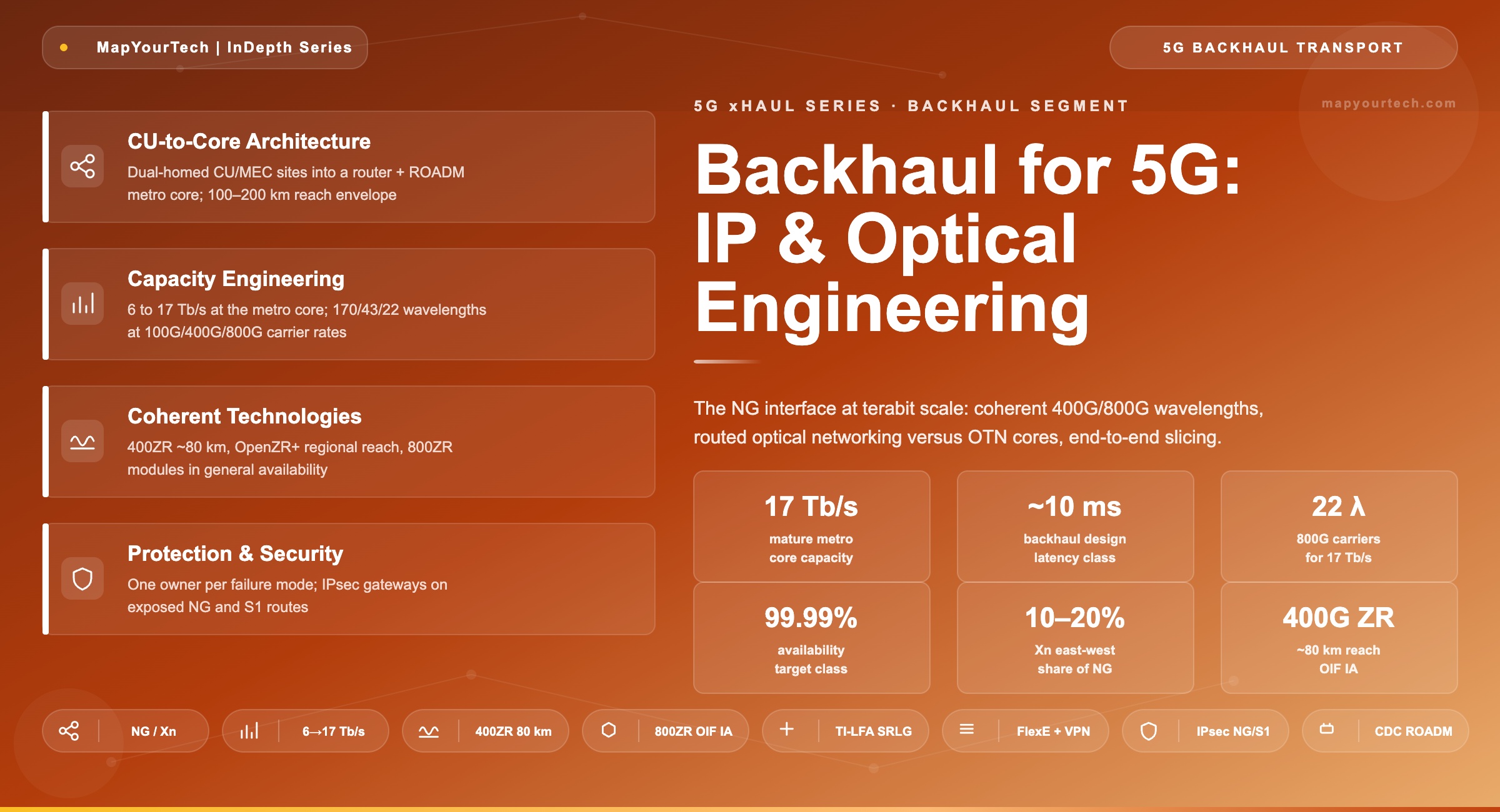
Backhaul for 5G: IP and Optical Network Engineering
Architecture, requirements, and product capabilities for the CU–core segment: the NG interface, terabit metro aggregation, coherent 400G/800G wavelengths, routed optical networking versus OTN cores, and end-to-end slicing.
1. Introduction
Backhaul is the transport segment between the centralized unit (CU) and the 5G core, carrying the 3GPP NG interface, and it is where 5G transport stops being a radio problem and becomes a capacity problem. A metro of 12,000 sites presents roughly 6 Tb/s of aggregate demand at the metro core in early deployment and around 17 Tb/s at maturity, per operator planning estimates published in industry white papers. No single number in the other two segments approaches that scale, and the engineering follows the scale: coherent wavelengths, terabit routers, and wavelength-layer switching live here.
The latency pressure relaxes in proportion. With the real-time radio layers terminated at DU and CU, the NG interface works in a ~10 ms design class over 100 to 200 km of metro reach, which opens the technology space to long-reach coherent optics and multi-hop routed paths that fronthaul and midhaul exclude. East-west Xn traffic between gNB clusters adds 10 to 20 percent on top of NG volume, per operator planning estimates, flowing only between coordination neighbors. This article covers the CU-to-core architecture, the requirement set, capacity engineering and the interface ladder, the IP-coherent technology choices including routed optical networking versus OTN cores, slicing and security, protection, and a product capability checklist. The segment's position in the full three-segment model is set out in the companion overview of 5G transport network architecture.
Takeaway: Backhaul trades the microsecond discipline of the lower segments for terabit scale: 6 to 17 Tb/s at the metro core, a ~10 ms latency class, and 100 to 200 km reach. The engineering center of gravity moves from timing to capacity, availability, and cost per bit.
2. Backhaul Architecture: CU to Core
2.1 What NG Connects
The NG interface joins the CU, hosting Packet Data Convergence Protocol and Radio Resource Control at the metro aggregation site, to the 5G core functions: the user plane function (UPF) terminating user traffic and the access and mobility management function (AMF) terminating signaling. Where 4G S1 traffic shares the network, it follows the same paths to the evolved packet core. The Xn interface (and eX2 toward 4G) adds east-west flows between gNB clusters for handover and dual connectivity, at 10 to 20 percent of NG volume per operator planning estimates, and only between adjacent clusters, so the metro core does not need any-to-any east-west capacity.
Core placement defines reach. Centralized cores put UPF in regional data centers 100 to 200 km out; edge-cloud designs pull UPF and multi-access edge computing into the metro aggregation sites themselves, shortening the user-plane backhaul to tens of kilometers while signaling continues to the region. Both patterns coexist in one network, sliced by service, which is why the transport beneath them is built as a general-purpose metro core rather than a dedicated mobile overlay.
2.2 Physical Topology
The physical pattern is a metro core ring or partial mesh of combined router and ROADM sites. Each CU/MEC aggregation site dual-homes into two core nodes so that no single node failure isolates a population of radios. Above the metro, regional links run coherent wavelengths toward the core data centers and internet peering. The wavelength layer (ROADM-switched DWDM) and the packet layer (terabit routers) are engineered together: wavelengths express through intermediate sites the packet layer has no business touching, and the routers groom everything else.
Takeaway: Backhaul architecture is a two-layer metro core: ROADM wavelengths underneath, terabit routers on top, CU sites dual-homed into it, and core placement (regional versus edge UPF) deciding how far the user plane travels. East-west Xn capacity is needed only between neighbors, never any-to-any.
3. Transport Requirements
The backhaul requirement set is dominated by capacity and availability, with latency and security as bounding conditions rather than drivers. The values below come from 3GPP end-to-end targets, operator planning estimates published in industry white papers, and standard metro engineering practice.
Capacity must track the aggregation arithmetic of Section 4: roughly 6 Tb/s at the metro core early, 17 Tb/s at maturity for a 12,000-site metro, plus 10 to 20 percent Xn east-west between neighboring clusters. Latency sits in a ~10 ms design class, derived from the 4 ms eMBB end-to-end user-plane target of 3GPP TR 38.913 applied to services that traverse the full metro, comfortably met at 100 to 200 km (1 ms of fiber delay) with several routed hops. Availability targets 99.99 percent or better for the population behind each CU, which forces dual-homing, sub-50 ms restoration, and no single point of failure in the core. Security follows from exposure: NG and S1 user-plane traffic crossing shared or leased infrastructure is commonly protected with IPsec gateways at the CU and core edges, and the transport must carry that encrypted load without visibility-based optimizations. Slicing must extend end to end, since the slice that began in fronthaul terminates at the UPF.
| Requirement | Value | Source / driver | Design consequence |
|---|---|---|---|
| Metro core capacity | 6 → 17 Tb/s | Operator planning estimates, 12,000-site metro | Coherent DWDM, terabit routers |
| East-west (Xn) | 10–20% of NG | Operator planning estimates | Neighbor-only capacity, not any-to-any |
| Latency class | ~10 ms design | 3GPP TR 38.913 end-to-end targets | 100–200 km reach, multi-hop routing allowed |
| Availability | 99.99%+ | Population behind each CU | Dual-homing, < 50 ms restoration |
| Security | IPsec common on NG/S1 | Shared/leased infrastructure exposure | Gateway capacity at CU and core edges |
| Slicing | End-to-end | 5G service classes | FlexE / VPN+SR continuity to the UPF |
Takeaway: Backhaul requirements rank capacity first, availability second, latency a distant third. The ~10 ms class is easy; the 17 Tb/s and the 99.99 percent are the engineering work, and IPsec plus end-to-end slicing ride along as non-negotiable boundary conditions.
4. Capacity Engineering and the Interface Ladder
Backhaul capacity is the top of the aggregation pyramid. Per-site rates (5 Gb/s peak early, 20 Gb/s at maturity, per operator planning estimates) multiply across the metro and divide by statistical convergence, since metro-wide busy hours do not align; 4:1 to 6:1 ratios between access and core are the defensible range from the same estimates.
Ccore = ( Nsites × Rsite,peak ) / Kconv

Where:
  Nsites     = sites in the metro
  Rsite,peak = peak per-site rate (Gb/s)
  Kconv      = statistical convergence ratio (4–6)

Practical Example — metro core at maturity:
  12,000 sites × 20 Gb/s / 6 ≈ 40 Tb/s peak envelope;
  sustained engineering figure ≈ 17 Tb/s
  (operator planning estimates; early-stage figure ≈ 6 Tb/s)
The interface ladder converts those terabits into ports. CU/MEC sites uplink at N × 100GE; the metro core runs coherent wavelengths at 100G, 400G, or 800G per carrier. The wavelength count is the budget line: 17 Tb/s needs about 170 wavelengths at 100G, 43 at 400G, or 22 at 800G (derived arithmetic), and each step down the ladder shrinks the ROADM, amplifier, and operations load with it. The charts below show the demand growth and the wavelength arithmetic.
Figure 2: Metro core capacity for a 12,000-site metro, early versus mature deployment, per operator planning estimates published in industry white papers.
Figure 3: Wavelengths required to carry 17 Tb/s at each coherent carrier rate (derived arithmetic). The 400G and 800G steps are what keep the metro core physically and operationally buildable.
Practical Example — sizing a core link: Two core nodes carry one third of the mature metro load between them: about 5.7 Tb/s. At 100G that is 57 wavelengths on one span, beyond comfortable C-band channel plans once growth and protection are added. At 400G it is 15 wavelengths; at 800G, 8. The operator deploys 400G pluggables in router ports for the working load and reserves the 800G step for the next growth cycle, keeping one technology refresh in hand rather than spending both at once.
Takeaway: Backhaul capacity engineering is the convergence formula at metro scale plus the wavelength ladder: 17 Tb/s is 170 wavelengths at 100G but only 22 at 800G (derived). Carrier-rate selection, not fiber count, is the cost and operations decision in the metro core.
5. IP Core and Coherent Optical Technologies
5.1 Routed Optical Networking
Coherent pluggables moved the transponder into the router port and created the routed optical networking pattern: routers connect over DWDM line systems using QSFP-DD optics, and the standalone transponder shelf disappears from links the pluggables can reach. The OIF 400ZR Implementation Agreement defines the anchor interface, 400 Gb/s coherent for point-to-point links up to around 80 km in its amplified application; OpenZR+ extends the same form factor with higher-gain FEC and multi-rate modulation for regional distances. The boundary between a ZR-class pluggable and an embedded high-performance transponder is a reach-and-margin decision, worked through in the MapYourTech comparisons of ZR versus ZR+ coherent standards and coherent versus direct-detect transceivers.
The 800G step follows the same pattern one generation later: the OIF 800ZR Implementation Agreement was published in late 2024, with module general availability through 2025, and the MapYourTech deep dive on 800G ZR and ZR+ coherent optics covers the baud-rate and reach trade-offs. For metro-core spans inside the ZR/ZR+ envelope, the router port is now the default home of the wavelength.
5.2 The OTN Core Alternative and the Wavelength Layer
The OTN-switched core remains the alternative where sub-wavelength grooming, hard client isolation, and optical-layer protection carry the business case: ODUk containers groom 10G and 100G clients into wavelengths, ODUk SNCP and optical channel protection restore inside 50 ms without touching the IP control plane, and wholesale or enterprise services share the same fabric with mobile backhaul. The container mechanics are covered in the complete guide to optical transport networks.
Underneath either choice sits the ROADM layer: colorless, directionless (and where justified, contentionless) add/drop lets any wavelength reach any direction from any port, so capacity can be re-pointed by software as traffic shifts between core data centers. Wavelengths that transit a site express through the ROADM at negligible incremental cost, which is the structural argument for keeping the packet layer out of transit traffic entirely.
| Attribute | Routed optical networking | OTN-switched core |
|---|---|---|
| Wavelength source | 400G/800G ZR/ZR+ pluggables in router ports | Embedded transponders / muxponders |
| Grooming | Packet (statistical) only | ODUk sub-wavelength grooming |
| Protection | TI-LFA fast reroute | ODUk SNCP / optical channel, < 50 ms |
| Isolation | FlexE + VPN/SR constructs | ODUk hard channels native |
| Reach envelope | ZR ~80 km; ZR+ regional | Engineered per link, longest reaches |
| Multi-service | IP services natively | Wholesale/enterprise circuits natively |
| Best fit | IP-centric metro inside pluggable reach | Converged operator, grooming-heavy mix |
Takeaway: The backhaul technology decision is where the wavelength lives: in the router port (routed optical networking, 400ZR/ZR+ and now 800ZR) or in the transport shelf (OTN core with grooming and optical protection). The ROADM layer underneath is common to both, and expressing transit wavelengths past the routers is where the architecture saves its money.
6. Slicing, Security, and Service Isolation
The slice that began at the radio terminates at the UPF, so backhaul carries the final transport leg of every slice and must preserve the isolation contracted upstream. The layering matches midhaul: FlexE channels in 5 Gb/s granularity (or ODUk channels in OTN cores) for the URLLC slice's hard isolation, VPN instances with segment routing traffic engineering and hierarchical QoS for the soft eMBB and mMTC slices. The new element at this scale is slice accounting: per-slice counters at the metro core are where the operator proves the slice service-level agreement to enterprise customers, so the telemetry requirement is commercial, not just operational.
Security hardens at the same boundary. NG and S1 user-plane traffic crossing shared, leased, or physically exposed infrastructure is commonly protected with IPsec, terminated on gateways at the CU site and the core data-center edge. The transport consequence is twofold: gateway throughput must be dimensioned to the same 6 to 17 Tb/s growth curve as the links, and the encrypted payload defeats any mid-network optimization that depends on flow visibility, so QoS and slicing markings must survive in the outer headers. Designs that classify on inner-packet inspection fail on day one of IPsec.
Takeaway: Backhaul inherits the slice and adds the proof: hard FlexE/ODUk channels for URLLC, soft SR slices for the rest, and per-slice telemetry as the commercial evidence. IPsec on NG/S1 is the default posture on exposed infrastructure, and every QoS and slicing decision must work from outer headers only.
7. Protection and Availability
The availability target (99.99 percent or better for the population behind each CU) decomposes into three mechanisms that operate at different layers and timescales. Dual-homing removes the single point of attachment: each CU site connects to two core nodes, and a node loss re-converges traffic onto the survivor. TI-LFA fast reroute handles link and node failures inside the routed core in tens of milliseconds, with pre-computed backups covering shared-risk link groups so that a single duct cut does not take both "diverse" paths. Optical-layer protection (OLP on fiber routes, optical channel or ODUk SNCP in OTN cores) restores wavelengths beneath the packet layer inside 50 ms, invisible to routing entirely.
Adual = 1 − ( 1 − Asingle )2        Apath = Π Ai

Practical Example — what dual-homing buys (derived):
  Single attachment at 99.9% → 0.001 × 8,760 h = 8.76 h/yr down
  Dual, independent paths    → 0.0012 = 10-6 ≈ 31.5 s/yr
The arithmetic carries two design warnings. The squared term holds only if the two paths share no failure mode, which is what SRLG modeling protects; two “diverse” paths in one duct revert to single-path numbers on the day the duct is cut. And the series product punishes long chains: every element added to a path multiplies its unavailability into the total, which is the quantitative case for expressing transit wavelengths past intermediate routers.
The design discipline is layering without duplication: protect each failure mode once, at the layer that handles it fastest and cheapest, and let the layers escalate. Fiber cuts belong to the optical layer; node failures belong to TI-LFA and dual-homing; gateway failures belong to IPsec gateway clustering. Protecting the same cut at two layers buys race conditions, not availability. The full decision space across SNCP, OLP, and IP fast reroute is mapped in the MapYourTech deep dive on network protection in optical network architecture.
Practical Example — allocating failure modes to layers: A metro core review finds the same fiber route protected three times: OLP at the optical layer, SNCP at the ODUk layer, and TI-LFA at the IP layer. A cut triggers all three within milliseconds of each other, and the post-mortem shows traffic switched optically in 18 ms while the IP layer simultaneously rerouted onto a longer path, then flapped back. The fix removes SNCP from that route, declares the optical layer owner of fiber cuts, and tunes TI-LFA hold-down so IP reroute engages only if the optical switch fails. Availability improved by deleting protection, not adding it.
Takeaway: Backhaul availability is dual-homing plus one owner per failure mode: optical layer for cuts, TI-LFA for node and link loss, clustering for gateways. Overlapping protection at multiple layers degrades into races; the design goal is escalation, not redundancy stacking.
8. Product Capabilities Checklist
The Section 3 requirement set converts into the procurement lines below. Values marked typical vary by product class and should be confirmed against vendor specifications.
| Capability | Target | Why it matters here |
|---|---|---|
| Coherent ports | 400G ZR/ZR+ today, 800ZR-ready (QSFP-DD) | The wavelength ladder of Section 4 |
| Router capacity | Terabit-class fabric, N × 100/400GE faceplate | 6 → 17 Tb/s metro growth |
| Routing / TE | SR-MPLS or SRv6, flex-algo, TI-LFA with SRLG | Sub-50 ms reroute, latency-bounded paths |
| Hard slicing | FlexE in 5 Gb/s granularity, or ODUk channels | URLLC isolation to the UPF |
| OTN option | ODUk grooming and SNCP where deployed | Sub-wavelength services, optical protection |
| ROADM layer | Colorless/directionless add-drop, express transit | Software re-pointing of capacity |
| Security | IPsec gateway scale matched to link growth | NG/S1 protection on exposed routes |
| Telemetry | Streaming, per-slice and per-wavelength counters | SLA evidence and convergence validation |
| Control | Hierarchical SDN across IP and optical layers | Multi-layer path computation and restoration |
Takeaway: A backhaul RFP is decided on the multi-layer lines: coherent pluggable roadmap (400G now, 800ZR next), TI-LFA with shared-risk awareness, ROADM express capability, and telemetry granular enough to prove a slice SLA. Raw router capacity is the entry ticket, not the differentiator.
9. Deployment Patterns and Design Rules
Three patterns cover most metros. IP-over-DWDM throughout: routers with ZR/ZR+ pluggables over a passive or ROADM line system, the simplest stack where all spans sit inside pluggable reach and the service mix is IP-only. Converged OTN core: OTN switching with embedded coherent, carrying mobile backhaul beside wholesale wavelengths and enterprise private lines, where grooming and optical protection earn their cost. Hybrid: routed optical networking on the high-volume CU-to-core paths, OTN grooming at the edges of the service mix; most large operators land here, and the structural options are compared in the companion piece on optical transport architectures supporting 5G.
Four design rules apply across patterns. Dimension to the mature figure with staged deployment: build the fiber and ROADM plant for 17 Tb/s, light it for 6, and let the wavelength ladder carry the growth. Express transit optically: any wavelength that does not terminate at a site should pass through its ROADM, not its router. One protection owner per failure mode (Section 7). Account energy per bit at this scale: a metro core's power budget is dominated by coherent ports and router fabrics, and per-bit comparisons across the patterns follow the pJ/bit framework in the MapYourTech analysis of energy efficiency in optical networks.
Takeaway: Pattern selection follows the service mix: IP-only metros go routed optical end to end, converged operators keep OTN where grooming pays, and most large networks hybridize. Build plant for the mature 17 Tb/s, light it in stages, and keep transit traffic out of the routers.
10. Automation and Operations
Routed optical networking moves the wavelength into the router port, and it moves wavelength operations into the router’s management plane with it. ZR and ZR+ pluggables are configured and monitored through CMIS-class module interfaces exposed by the host platform, modeled in vendor-neutral form by the OpenConfig model for multi-vendor management; turn-up that once required transport-team coordination becomes a scripted router-port workflow. The optical line system underneath answers to its own domain controller through TAPI-class interfaces, while the IP domain feeds the controller hierarchy through BGP-LS (RFC 7752) topology export and PCEP (RFC 5440) path control, the multi-layer split framed by ACTN (RFC 8453).
Margin management is the closed loop that pluggable optics make practical. Pre-FEC error counts and SNR-class metrics stream continuously from every coherent port, and trend analysis flags a degrading wavelength while it is still error-free after FEC: aging, a dirty connector, or a slowly failing amplifier shows up as months of warning rather than a night of post-FEC errors. The automation pre-computes the alternate path, schedules the maintenance window, and converts what was an outage class into a work order class.
Capacity automation completes the set. CDC ROADM plant lets the controller re-point wavelengths as traffic shifts between core data centers, defragmentation runs are simulated against the live topology before execution, and per-slice counters at the metro core generate the SLA reports that Section 6 identified as commercial evidence. The operations output of the backhaul is not just packets delivered; it is proof, produced automatically, that each slice received what was sold.
Practical Example — a margin trend converted to a work order: Telemetry on a 400G wavelength shows pre-FEC performance eroding by roughly 0.8 dB of margin over four months, consistent with a degrading connector on one span. The link is still clean after FEC. The automation opens a ticket with the span identified, pre-computes a re-route onto a parallel wavelength, and the connector is cleaned in a scheduled window. Without the loop, the first symptom would have been post-FEC errors on live NG traffic at an unscheduled hour.
Takeaway: Backhaul automation is the multi-layer controller split (TAPI toward optics, PCEP/BGP-LS toward IP), CMIS-class scripting of pluggable wavelengths, closed-loop margin management from streamed pre-FEC telemetry, and automated slice SLA evidence. The segment that scales to terabits is also the one where manual operations stop scaling first.
11. Evolution and Outlook
Two forces reshape backhaul over the deployment cycle, and they pull in opposite directions. Capacity growth pushes the wavelength ladder upward: 400G pluggables are the present working step, 800ZR modules entered general availability through 2025 per the OIF trajectory, and each step keeps the wavelength count of Section 4 inside a manageable channel plan. Edge-cloud migration pulls the user plane downward: as UPF and MEC instances move into metro aggregation sites, a growing share of traffic terminates tens of kilometers from the radio instead of crossing the full metro, flattening the demand curve at the regional links even as access demand grows.
The control plane consolidates in parallel: hierarchical SDN spanning the IP and optical layers becomes the practical requirement once wavelengths are router-resident, because no single-layer view can compute a restoration that involves both a ROADM path and a TI-LFA backup. 5G-Advanced raises slice counts and SLA granularity rather than raw bandwidth, which lands on the telemetry and accounting lines of the checklist more than on the interfaces.
Takeaway: The backhaul roadmap is the 800G wavelength step up, the UPF/MEC pull downward, and multi-layer SDN binding the two. Plan capacity on the ladder, plan topology on edge-cloud placement, and plan operations on slice-grade telemetry.
Glossary
- AMF / UPF: Access and Mobility Management Function and User Plane Function; the 5G core endpoints of backhaul.
- CU: Centralized Unit; the RAN function whose NG interface backhaul carries.
- FlexE: Flexible Ethernet; calendar-based channelization in 5 Gb/s granularity for hard slice isolation.
- IPsec: IP security; the encryption commonly applied to NG/S1 user-plane traffic on exposed routes.
- NG / Xn: The 3GPP interfaces from gNB to core (NG) and between gNBs (Xn).
- ODUk SNCP: Optical Data Unit subnetwork connection protection; electrical-layer 1+1 protection in OTN.
- OLP: Optical Line Protection; optical-layer fiber-route switching.
- ROADM: Reconfigurable Optical Add-Drop Multiplexer; the wavelength-switching layer of the metro core.
- SR / SRv6 / TI-LFA: Segment Routing data planes and their topology-independent fast-reroute mechanism.
- SRLG: Shared Risk Link Group; links sharing a physical failure mode, modeled so backups avoid them.
- ZR / ZR+ / 800ZR: Coherent pluggable interface classes defined by OIF and the OpenZR+ MSA.
- 5GC: The 5G core network terminating NG.
References
- [1] 3GPP TR 38.913, Study on Scenarios and Requirements for Next Generation Access Technologies, 3GPP.
- [2] OIF, 400ZR Implementation Agreement, Optical Internetworking Forum.
- [3] OIF, 800ZR Implementation Agreement, Optical Internetworking Forum.
- [4] IETF RFC 8402, Segment Routing Architecture, IETF.
- [5] ITU-T G.709, Interfaces for the optical transport network, ITU-T.
- [6] Sanjay Yadav, "Optical Network Communications: An Engineer's Perspective" — Bridge the Gap Between Theory and Practice in Optical Networking.


