Protocols & APIs · NBI and SBI
Network Management Protocols and APIs: An Introduction
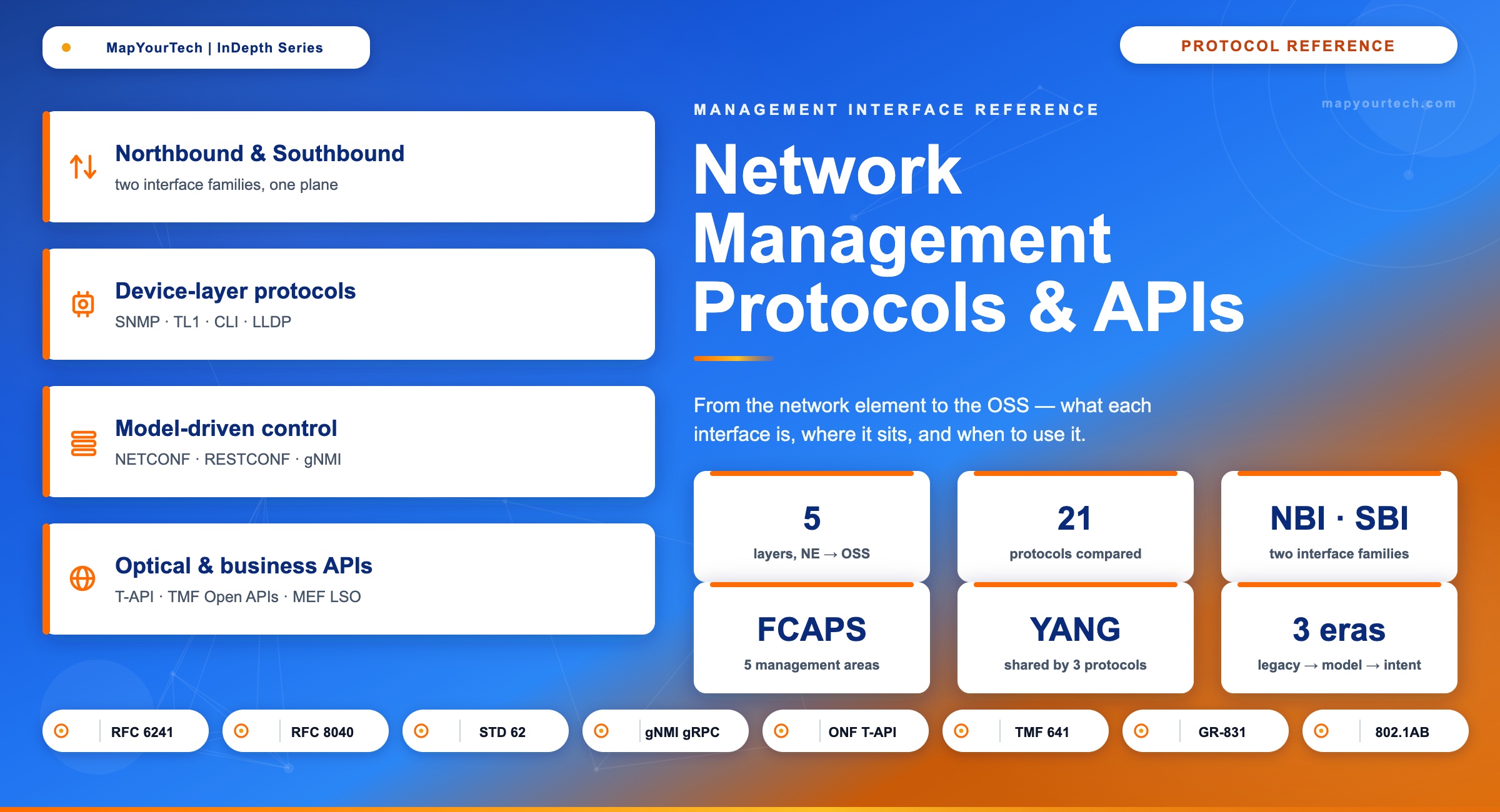
From SNMP and TL1 at the network element to TMF Open APIs at the business layer: what every management interface is, where it lives on the northbound or southbound, and how to choose the right one for optical and networking systems.
Introduction
A single 100G wavelength service touches a dozen interfaces before it earns revenue. A customer order arrives at a business system. An operations system decomposes it into a service and asks an orchestrator to build a path. The orchestrator computes a route, then tells an optical domain controller to light a channel. The controller configures a coherent transponder, sets the modulation format and FEC, asks a ROADM to cross-connect the wavelength, and adjusts amplifier gain along the line. Every one of those hops speaks a different protocol, and an engineer who cannot name which interface lives where ends up integrating blind.
The interfaces are not interchangeable. SNMP polls a counter but cannot safely commit a transactional configuration. TL1 provisions a legacy SONET ring but was never built for streaming telemetry. NETCONF holds a candidate datastore and a rollback; gNMI pushes a hundred metrics a second; the ONF Transport API hides a multi-vendor optical line system behind one model. Each was designed for a job, and using the wrong one turns a clean integration into a maintenance burden that outlives the project.
This guide maps the major management protocols and APIs used in optical and networking systems across the full stack, from the network element up to the business support system. It separates the two axes every interface sits on, the southbound that controls a layer and the northbound that exposes it, names what each protocol is and where it belongs, and closes with a decision flow and an interactive selector you can use to compare them directly.
1. Two questions every interface answers
Every management interface answers two questions before anything else: which layer does it touch, and which direction does it face. Get those two right and the rest of the integration follows. Confuse them and you will reach for a protocol that physically cannot do what you need.
1.1 Southbound controls; northbound exposes
Southbound interfaces (SBI) face the layer being controlled. An SBI carries configuration down to a device, pushes provisioning commands, and pulls back state or telemetry. The controller-to-device link, the EMS-to-network-element link, and the orchestrator-to-controller link are all southbound from the perspective of the system doing the controlling.
Northbound interfaces (NBI) face the layer above. An NBI exposes abstracted capability upward: a service model instead of a box configuration, an inventory instead of a chassis, an alarm stream instead of a raw trap. The element manager presents its network elements to the network manager through an NBI; the network manager presents services to the operations system through another. The whole point of an NBI is to hide detail, so the layer above works with intent rather than wiring.
1.2 The management plane mediates both
Between the two interface families sits a management and control plane: an element manager, a network manager, an SDN controller, or a service orchestrator. Its job is to terminate southbound protocols on one side, build a coherent model of inventory, topology, services, and faults, and re-present that model northbound through standardized, secured APIs. A controller might speak NETCONF and gNMI to the devices below it while answering the orchestrator above in RESTCONF, and publishing alarms onto a Kafka stream for the assurance system to consume.
One link, two names, is the idea that trips people up. The interface between an element manager and a network element is the element manager's southbound and the network element's northbound at the same time. Direction is always relative to the layer you are standing on, which is why the same protocol, RESTCONF for instance, appears on both axes depending on who is calling whom.
1.3 Vertical north–south, horizontal east–west
Network element, element manager, network manager, orchestrator, OSS, business system — the management stack runs vertically, and every interface between two adjacent layers points either up or down. Up is northbound, toward abstraction and business intent; down is southbound, toward device detail. North–south is the management plane’s axis, and it exists because operators build their tooling in vertical tiers, where each tier consumes the model the tier below publishes.
Two routers exchanging IS-IS or BGP routes between themselves never touch a management layer; that link is east–west, the horizontal axis of network integration. An optical control plane signals a path hop by hop with GMPLS, and two domain controllers exchange topology across a boundary so one service can span both. Each link stays on a single tier and moves sideways between peers, which is why the industry borrowed the compass term east–west for it. East–west carries no abstraction gradient, the peers are co-equal, and that is the structural difference from the north–south management axis.
North of what is the question that settles every apparent contradiction. The compass points relative to the element you take as the reference. From a network element, northbound is the link up to its element manager. From that element manager, northbound is the link up to the network manager, while southbound is the link down to the element, the same wire the element called its own northbound. Re-root on the OSS and the network manager’s northbound becomes the OSS’s southbound. The bytes on the wire are identical at every step; only the name changes, because the name records a point of view.
Takeaway: Before picking a protocol, fix two coordinates. Which layer does the interface touch, and which way does it face. Southbound carries control and telemetry to the layer below; northbound exposes an abstracted model to the layer above. The same wire is one layer's southbound and the next layer's northbound, so the names describe a viewpoint, not a fixed property of the protocol. North–south is the vertical axis of management integration, while east–west is the horizontal axis where peers exchange directly without crossing a layer.
2. The layered management stack
ITU-T Recommendation M.3010 drew the reference model the industry still leans on four decades later. It splits management into logical layers stacked above the network itself: the element management layer that talks to one vendor's boxes, the network management layer that stitches a multi-vendor network together, the service management layer that turns network capability into customer services, and the business management layer that handles orders, billing, and partners. Each layer manages the one below through that layer's southbound, and exposes itself upward through its northbound.
FCAPS names what management actually does at every layer: Fault, Configuration, Accounting, Performance, and Security. A protocol earns its place by how well it serves these. SNMP and TL1 grew up around Fault and Performance; NETCONF and gNMI are built for Configuration and streaming Performance; the business APIs at the top sit in Accounting and service fulfilment. When you evaluate an interface, ask which FCAPS areas it covers well and which it only pretends to.
2.1 The modern mapping
In a deployed network the layers map to concrete systems: the network element, an element management system, a network manager or service-and-network orchestrator with its domain controllers, the operations support system, and the business support system. SDN controllers and orchestrators collapsed parts of the old hierarchy by computing paths centrally and abstracting whole domains, so the network management layer now often appears as a controller-plus-orchestrator pair rather than a single monolithic NMS.
Disaggregation changed the element layer too. When an optical line system and its transponders come from different vendors, no single element manager owns the whole node, so a domain controller takes over the element-management job and speaks open device models southbound. The boundary names survive even when the boxes that fill them change shape.
2.3 The complete protocol map
Every protocol in this guide maps to a network layer and a job. The matrix below places the optical, OTN, Ethernet, and IP/MPLS layers against the four things management does at each one, configure, monitor, control, and model, and shows the model-driven protocols cutting across all of them. Read a row to see what manages a given layer; read a column to see which protocol does a given job.
2.4 One-page reference: NE to OSS
The stack below puts every layer and its interfaces on one page. Each band is a layer, from the physical network elements at the bottom to the OSS and business systems at the top; the cards inside name what that layer does, and the protocols between two bands are the interfaces that join them. Keep it open beside an integration design, it answers which protocol crosses which boundary without paging back through the sections above.
Takeaway: The TMN layers and FCAPS still frame the whole picture. Read any integration by asking which boundary it crosses, then by which FCAPS areas the interface there actually serves. The boundary names persist even as controllers and orchestrators reshape the systems that fill them.
3. Southbound to the device
At the bottom of the stack sit the protocols that touch the network element directly. These split into two generations: the text-and-poll protocols that grew up with SONET and IP in the 1990s, and the model-driven protocols covered in the next section. The older set is still everywhere, because the installed base does not retire on a standards committee's schedule.
3.1 SNMP — the monitoring floor
Simple Network Management Protocol is the floor every network manager can stand on. A manager polls counter and status variables from an agent on the device, and the agent pushes an asynchronous trap when something changes. Three versions ship today. Version 1 (RFC 1157) carries a cleartext community string as its only credential. Version 2c added GETBULK for efficient table walks, INFORM for acknowledged notifications, and 64-bit counters for gigabit interfaces, but kept the same cleartext community model. Version 3 (STD 62) is the one to deploy: its User-based Security Model authenticates with HMAC-SHA and encrypts with AES, and its view-based access control limits what each user can read or write.
The data lives in a Management Information Base, a tree of object identifiers described in SMIv2, and travels as ASN.1 over UDP port 161 for polls and 162 for traps. SNMP is strong at Fault and Performance and weak at Configuration: it can SET a variable, but it has no transaction, no candidate datastore, and no rollback, so bulk provisioning through SNMP is a known way to half-configure a device.
$ snmpget -v3 -l authPriv -u noc roadm-07 ifOperStatus.13
IF-MIB::ifOperStatus.13 = INTEGER: down(2)

# Asynchronous trap arriving at the manager on UDP 162
roadm-07  snmpTrapOID.0 = IF-MIB::linkDown
ifIndex.13 = 13 severity = majorNever run SNMP v1 or v2c across an untrusted path. The community string is sent in cleartext on every packet, so anyone who can sniff the management network can read it and issue SET commands. Use v3 at the authPriv level, and treat read-write community strings on legacy gear as a liability to be fenced off behind strict access control.
3.2 CLI over SSH — ubiquitous and brittle
Every device ships a command line, and for interactive work it is the right tool. An engineer connects over SSH, reads human-formatted output, and makes a change with a verb the vendor chose. The problem starts when a script does the same thing. CLI output is unstructured text, so automation has to parse it by position, a practice called screen-scraping that breaks the day a vendor reorders a column or renames a field. CLI is the path for troubleshooting and for features that have not yet reached a model, not the path for fleet-scale change.
3.3 TL1 — the optical transport incumbent
TL1 is the text protocol that still runs much of the North American optical and access transport base. Bellcore defined it in 1984, building on the ITU-T Z.300 man-machine language, to replace the private ASCII commands every vendor had invented. A TL1 message is plain text addressed by three fields: the TID names the target network element, the AID names the resource inside it, and the CTAG correlates the response to the command. The element also emits autonomous messages on its own when an alarm raises or clears.
One property keeps TL1 in service on optical rings. A SONET ring is reached through a single gateway network element, which uses the TID to forward each command to the right node, so an operations system manages the whole ring through one connection. TL1 covers Fault, Configuration, and Performance well, but it is session-oriented and verbose, and it was never built for the streaming telemetry that modern assurance wants.
RTRV-ALM-ALL:BERLIN-OADM-3::CTAG123;

   BERLIN-OADM-3 2026-05-29 14:30:07
M  CTAG123 COMPLD
   "OTU4-1-3-2:CR,LOS,SA:Loss of Signal on line side"
   "EDFA-1-2:MJ,GAINLOW,NSA:Pre-amp gain below threshold"
;3.4 LLDP — how the controller learns the wiring
LLDP is the quiet protocol that saves operators from typing topology in by hand. Defined in IEEE 802.1AB, each device periodically advertises its chassis identifier, port, and capabilities to its directly attached neighbours in a Layer 2 frame. A controller that collects these advertisements can reconstruct physical adjacency automatically. In optical networks the same discovery rides the optical supervisory channel between sites, so the line system learns its own topology. LLDP does not configure anything; it only answers the question of what is connected to what, which is the input every controller needs before it can compute a path.
Takeaway: The device-layer incumbents each own a niche. SNMP is the universal monitor; CLI is for interactive work and gap-filling; TL1 still provisions legacy optical and access transport; LLDP discovers adjacency. None of them gives you transactional, model-driven configuration at scale, which is exactly the gap the next generation was built to fill.
4. Model-driven southbound: NETCONF, RESTCONF, gNMI
Model-driven management replaced text parsing with a shared schema. Instead of guessing at CLI output or hand-coding per-vendor logic, the manager and the device agree on a data model, and every operation reads or writes a defined path in that model. The schema is YANG, and three protocols carry it.
4.1 YANG — the schema underneath all three
YANG is the modeling language that ties the modern protocols together, the way SMIv2 underpins SNMP. Defined in RFC 7950 for version 1.1, it describes configuration and operational state as a tree of typed, constrained nodes. A model says an interface has a name, an admin-state, and a set of counters, what types they take, and which are writable. NETCONF, RESTCONF, and gNMI all move YANG-modelled data; they differ in transport, encoding, and what guarantees they give around a change. The model can be vendor-specific, or one of the open model sets covered in the optical section.
4.2 NETCONF — transactional configuration
NETCONF and YANG together give the strongest configuration guarantees in the set. Defined in RFC 6241 and run over SSH on TCP port 830, NETCONF exchanges XML remote procedure calls and treats device state as datastores. The candidate datastore is the feature that matters most: you edit a copy of the configuration, validate it, lock the device so no one else changes it underneath you, then commit the whole change atomically or roll it back. That all-or-nothing behaviour is why NETCONF is the path for provisioning that must not leave a device half-configured.
<!-- Edit a copy, then commit it atomically -->
<rpc message-id="101" xmlns="urn:ietf:params:xml:ns:netconf:base:1.0">
  <edit-config>
    <target><candidate/></target>
    <config>
      <interfaces xmlns="http://openconfig.net/yang/interfaces">
        <interface><name>och-1/3/2</name>
          <config><enabled>true</enabled></config>
        </interface>
      </interfaces>
    </config>
  </edit-config>
</rpc>
<rpc message-id="102"><commit/></rpc>4.3 RESTCONF — the same models over HTTP
RESTCONF takes the same YANG models and exposes them over plain HTTP. Defined in RFC 8040, it maps the familiar verbs, GET, POST, PUT, PATCH, and DELETE, onto YANG resources addressed by URL, and carries data as JSON or XML. It is a deliberate subset of NETCONF: there is no candidate datastore and no locking, so you trade transactional safety for the ease of using ordinary web tooling. For simple create-read-update-delete work and for integration with HTTP-native pipelines, that trade is usually worth it.
curl -k -X PATCH \
  https://roadm-07/restconf/data/openconfig-terminal-device:terminal-device/logical-channels/channel=20001 \
  -H "Content-Type: application/yang-data+json" \
-d '{ "openconfig-terminal-device:channel": { "config": { "admin-state": "ENABLED" } } }'4.4 gNMI — built for streaming telemetry
gNMI and streaming telemetry solve the problem the others handle poorly: getting a lot of state off a device, fast. Built on gRPC over HTTP/2 with protobuf encoding, gNMI offers four operations, Capabilities, Get, Set, and Subscribe. Subscribe is the one that changed monitoring. Instead of the manager polling every few seconds, the device streams a value the moment it changes (ON_CHANGE) or on a fixed sample interval, pushing hundreds of metrics a second where SNMP would choke. Protobuf is roughly three to ten times smaller on the wire than the equivalent XML, and mutual TLS secures the channel. gNMI pairs with gNOI for operational actions and gRIBI for route injection.
$ gnmic -a roadm-07:9339 --tls-cert noc.crt --tls-key noc.key \
    subscribe --mode stream --stream-mode on_change \
    --path "/components/component/optical-channel/state/output-power"

{"source":"roadm-07","timestamp":"...","value":{"instant":-2.1,"units":"dBm"}}| Protocol | Transport & port | Encoding | Data model | Transactional | Telemetry | Best fit |
|---|---|---|---|---|---|---|
| SNMP | UDP 161 / 162 | ASN.1 / BER | MIB (SMIv2) | No | Poll plus traps | Universal monitoring |
| TL1 | TCP session | ASCII (MML) | Command verbs | Partial | Autonomous alarms | Legacy optical / SONET provisioning |
| NETCONF | SSH 830 | XML | YANG | Yes (candidate + commit) | On request | Transactional multi-vendor config |
| RESTCONF | HTTPS 443 | JSON / XML | YANG | No (subset) | SSE notifications | REST and DevOps CRUD |
| gNMI | gRPC / HTTP2 9339 | Protobuf | OpenConfig YANG | Set, no candidate | Streaming ON_CHANGE | High-volume telemetry plus config |
Takeaway: All three modern protocols carry the same YANG models, so the choice is about guarantees, not data. Reach for NETCONF when a change must be atomic, RESTCONF when web tooling and simple CRUD win, and gNMI when you need to stream state off a fleet faster than polling allows. Most real automation stacks run more than one at once.
5. The optical domain and its controller
The optical layer needed models for the same reason the packet layer did, but it arrived later and split into two efforts. Driving both is disaggregation: when an operator buys the optical line system from one vendor and the transponders from another, no single element manager owns the whole node, so the management has to be built on open models that any controller can speak.
5.1 Two open device models
OpenConfig is a set of vendor-neutral YANG models led by operators and Google. It is not a protocol; it is a common model set carried over NETCONF, RESTCONF, or gNMI, and it covers optical alongside IP through modules such as terminal-device for coherent transponders and optical-amplifier for line gear. Write automation against the OpenConfig terminal-device model and it runs across any transponder that supports it, without device-specific code.
OpenROADM takes a more optical-specific path. It is an operator-led interoperability specification with device, network, and service YANG models, run over NETCONF on TCP port 830. Its device model describes shelves, circuit-packs, and ports; its interface models describe the optical layers an engineer recognizes (OTS, OMS, OCH, OTU, ODU); and its service model drives end-to-end wavelength provisioning. Where OpenConfig aims for one model across all gear, OpenROADM aims for ROADMs and transponders from different vendors to interoperate on one line system.
5.2 Disaggregation, partial and full
Disaggregation comes in degrees, and the degree decides which models you need. In partial disaggregation the transponders are opened up but the line system stays a single-vendor open line system; a controller speaks OpenConfig or gNMI to the transponders and a line-system interface to the optical line system. In full disaggregation the ROADMs open up too, and OpenROADM or vendor models reach every node. Open-source controllers such as the ONOS-based Open Disaggregated Transport Network project showed the pattern working: open device models below, one abstracted view above. The physical building blocks behind this are covered in detail in our note on ROADM architecture.
5.3 The controller has two faces
An optical domain controller exists to hide complexity, and it does so by presenting two different interfaces. Southbound it speaks each device's native model, NETCONF with OpenROADM to a ROADM, gNMI with OpenConfig to a transponder. Northbound it presents the ONF Transport API, a vendor-neutral model carried over RESTCONF that describes the optical domain as topology, connectivity services, and path-computation requests. The orchestrator above asks for a connection between two endpoints and never sees a circuit-pack. Building this control plane well is the subject of our optical network automation guide.
Optical device models are less mature than their IP counterparts, and vendor-specific extensions are still common for features the base models do not yet cover. Plan for an adaptation layer at the controller: the northbound Transport API stays clean, while the southbound driver absorbs the per-vendor differences. Treat full multi-vendor optical interoperability as a target you converge on, not a property you get for free.
Takeaway: In the optical domain, OpenConfig and OpenROADM are device models, not protocols; they ride NETCONF, RESTCONF, or gNMI. The Transport API is the northbound that hides the whole domain. A controller that speaks device models below and T-API above is what turns a disaggregated, multi-vendor optical network into something an orchestrator can drive.
6. SDN control and discovery interfaces
Above the device, a controller's southbound does a different job from configuring a box. It programs forwarding behaviour and computes paths, and the protocols here reflect that. Three carry the load in IP and transport networks, and one framework ties them together across domains.
6.1 OpenFlow
OpenFlow was the protocol that launched software-defined networking. A controller programs the flow, group, and meter tables of a switch directly over TCP port 6653, separating the control plane from the forwarding plane outright. It found its home in data-centre and campus fabrics and in research, where per-flow control is the point. In wide-area and optical networks it is rare today; many fabrics moved to a model where gNMI carries configuration and BGP carries reachability, leaving OpenFlow to specific niches.
6.2 PCEP and BGP-LS
PCEP and BGP-LS work as a pair for centralized traffic engineering. PCEP, defined in RFC 5440 and extended for central control in RFC 8283, runs between a router and a Path Computation Element on TCP port 4189. A stateful PCE computes traffic-engineered paths and instals them as segment-routing or RSVP-TE tunnels, then updates them as the network changes. BGP-LS, defined in RFC 7752, is the feed that makes this possible: routers distribute their IGP link-state and traffic-engineering attributes, including metrics, reserved bandwidth, and shared-risk groups, into BGP so the controller can assemble a network-wide topology across multiple IGP domains without polling each node. BGP-LS carries topology, not changes; PCEP acts on it.
6.3 ACTN for multi-domain transport
ACTN is an abstraction hierarchy, not a single protocol. Defined in RFC 8453, it places a Multi-Domain Service Coordinator over per-domain Provisioning Network Controllers, with standard YANG interfaces between them: a customer interface (CMI) above the coordinator, a multi-domain interface (MPI) between coordinator and controllers, and a southbound interface from each controller to its devices. The pattern lets each domain keep its own controller while presenting an abstracted view upward, which is how a multi-layer optical-plus-packet network gets orchestrated as one service. The interplay of layers here also shapes how restoration is designed, a topic covered in our note on network protection.
Takeaway: Control-plane interfaces are about paths and forwarding, not box configuration. BGP-LS gives a controller the topology, PCEP lets it compute and instal traffic-engineered paths on that topology, and ACTN coordinates the whole thing across domains and layers. OpenFlow still exists but has narrowed to specific fabrics.
7. Northbound from EMS and NMS
Climbing one layer, the element-manager and network-manager northbound is where management systems integrate with each other, and it shows the generational split more sharply than anywhere else in the stack. The legacy interfaces here are object-oriented and heavy; the modern ones are RESTful and light.
7.1 CORBA and MTNM
The classic transport EMS-to-NMS interface is CORBA-based MTNM. The TM Forum Multi-Technology Network Management suite defined it across three documents, a business agreement, an information model, and a CORBA solution set known by its number, TMF814, and ITU-T anchored it as the network-to-element-management Q interface in the M.3170 series. It covers full FCAPS for multi-technology transport through CORBA objects, modelling the network as termination points and subnetwork connections, and uses the OMG notification and log services for events. It works, and a great deal of deployed transport is still managed this way.
The cost is weight. CORBA needs an object request broker runtime on both ends, the interface is tightly coupled, and the IDL versioning makes upgrades painful. MTOSI, the TM Forum's TMF854, was the XML answer to some of this: an operations-system to operations-system interface carried over SOAP or a message bus, exchanging inventory, provisioning, and notifications in XML. Both belong to the previous generation.
7.2 The modern northbound
New builds replace CORBA and MTOSI with REST. An optical domain controller exposes the Transport API over RESTCONF; a network manager exposes a REST or RESTCONF interface that the orchestration layer above consumes. The shift is the same one the device layer made, from object-oriented, tightly coupled interfaces to resource-oriented, loosely coupled ones, and it is why a modern integration reads as JSON over HTTP rather than IDL over an ORB.
An ORB-based MTNM interface couples the network manager and element manager at the object level, so a model change on one side can break the other, and the runtime dependency complicates every upgrade. The practical path off it is an adapter that terminates the legacy CORBA interface and re-presents the same inventory and faults as a Transport API or REST endpoint, letting new systems integrate over HTTP while the legacy element manager lives out its service life behind the adapter.
Takeaway: The EMS and NMS northbound is mid-migration. CORBA-based MTNM and XML-based MTOSI still carry a large installed base of transport management, but every new interface is REST or RESTCONF, with the Transport API as the optical-domain standard. When you meet a CORBA northbound, plan the adapter rather than extend it.
8. The OSS layer: TMF Open APIs and ODA
At the operations layer the interfaces stop describing devices and start describing services and the business. The TM Forum Open APIs are the standard here: a large, openly licensed suite of REST and JSON interfaces that let ordering, activation, inventory, and assurance systems talk to each other with one shared information model rather than a web of point-to-point integrations.
8.1 The Open API suite
Every TMF Open API follows the same design pattern, published as open guidelines and licensed under Apache 2.0: resources exposed through create-read-update-delete operations, task operations for actions that are not simple CRUD, attribute selection and filtering on queries, and a hub-and-event mechanism for notifications. The suite is organized by domain. On the service side, TMF641 places a service order, TMF640 activates and configures the service, TMF638 holds the service inventory, and TMF633 the service catalog. On the resource side sit the resource catalog, order, and inventory APIs. Assurance is covered by TMF642 for alarms and TMF688 for events. An optical wavelength service is ordered through TMF641 and recorded in TMF638 exactly as any other service would be.
# TMF641 Service Ordering: request a 100G wavelength between two nodes
POST /tmf-api/serviceOrdering/v4/serviceOrder HTTP/1.1
Host: oss.example.net
Content-Type: application/json

{
  "category": "wavelength",
  "serviceOrderItem": [{
    "action": "add",
    "service": {
      "serviceType": "OTU4",
      "serviceCharacteristic": [
        { "name": "aEnd", "value": "BERLIN-OADM-3" },
        { "name": "zEnd", "value": "MUNICH-OADM-1" },
        { "name": "rate", "value": "100G" }
      ]
    }
  }]
}8.2 ODA and the event bus
The Open Digital Architecture is where those APIs become a running system. ODA defines cloud-native software components that sit on a shared platform and carry a self-describing envelope of metadata so their lifecycle can be automated, with the APIs as the contracts between them. It is built on the shared information model that has underpinned the framework for years and succeeds the earlier process, information, and application maps as the runtime architecture rather than a set of documents.
Assurance increasingly runs on an event bus rather than request-response polling. Alarms from TMF642, events modelled by TMF688, and streamed device telemetry are published onto a Kafka topic that many systems consume independently: an analytics pipeline, a service-impact engine, a closed-loop controller. The pattern decouples the system raising an event from the systems acting on it, which is what lets assurance scale to the volume modern monitoring produces. The metrics behind those alarms, and how they are estimated, are the subject of our work on optical performance monitoring.
Takeaway: At the OSS layer, integration means TMF Open APIs over REST and JSON, with a common information model so service order, activation, inventory, and assurance speak the same language. ODA turns that suite into a cloud-native runtime, and a Kafka event bus carries alarms and telemetry to whoever needs them.
9. The BSS and inter-provider edge
At the top of the stack the interfaces handle commerce and crossing company boundaries. The protocols are still REST and JSON, but the concerns shift from network state to products, customers, money, and partners.
9.1 Commerce APIs
The business support system runs on its own set of TMF Open APIs. TMF620 manages the product catalog, TMF622 places product orders, TMF666 manages billing accounts, and TMF678 handles customer bills. These connect the customer-facing channels and commerce systems to the operations layer below, so a product order at the top decomposes cleanly into the service orders that TMF641 carries down to the network.
9.2 MEF LSO reference points
MEF's Lifecycle Service Orchestration architecture names the interface points for service orchestration, both inside a provider and between providers, and aligns them with the TMF model. Three run north-south within a provider: Legato connects business applications to the service orchestrator, Presto connects the orchestrator to network control, and Adagio connects control to the elements. Four run east-west between companies: Cantata and Sonata for business functions, Allegro and Interlude for operational functions. Sonata is the one operators reach for most, because it standardizes inter-carrier ordering, quoting, and serviceability, which is what makes an off-net circuit orderable through an API instead of a spreadsheet and an email.
9.3 Virtualization and intent
Two more interface families round out the top of the stack. ETSI's NFV management and orchestration defines how virtualized network functions are deployed and run, through interfaces between an orchestrator, the function managers, and the infrastructure manager, which matters wherever network functions have moved into software. Above all of it, intent-based interfaces are emerging: rather than telling the network how to configure itself, an operator states the outcome, and the system works out the configuration, an approach formalized in industry intent guidelines, in 3GPP's intent-driven management for mobile networks, and in the IETF's intent-based networking work. The same direction drives the fully automated operations described in our study of hyperscaler optical network automation.
Takeaway: The business edge runs on TMF commerce APIs internally and MEF LSO reference points for orchestration and inter-carrier ordering, with NFV-MANO for virtualized functions. Intent-based interfaces are the next layer of abstraction, where the operator declares the outcome and the stack below realizes it across every interface in this guide.
10. Choosing the right interface
Choosing comes down to two filters and then a short list. First, which boundary does the integration cross. Second, which direction does it face. Those two answers narrow twenty-plus protocols to two or three candidates, and the candidates differ on guarantees, not on whether they can technically move the data. The flow below walks the most common decisions.
| If you need to | Reach for | Because |
|---|---|---|
| Monitor a mixed multi-vendor estate | SNMP v3 | Universal agent support; traps for fault, polling for performance |
| Provision a legacy SONET or optical ring | TL1 | Incumbent on installed transport; one gateway NE reaches the ring |
| Make an atomic, multi-step config change | NETCONF | Candidate datastore, locking, and commit or rollback |
| Integrate config with web or DevOps tooling | RESTCONF | YANG models over HTTP verbs and JSON |
| Stream sub-second state off a large fleet | gNMI | gRPC streaming, ON_CHANGE updates, compact protobuf |
| Run one model across multi-vendor gear | OpenConfig | Vendor-neutral YANG carried over NETCONF or gNMI |
| Provision multi-vendor ROADMs interoperably | OpenROADM | Optical device, network, and service YANG |
| Abstract an optical domain to the orchestrator | ONF T-API | Topology and connectivity services over RESTCONF |
| Compute and instal TE paths centrally | PCEP + BGP-LS | Central path computation on a network-wide topology |
| Order, activate, or inventory a service in the OSS | TMF Open APIs | Common model: TMF641, 640, 638, 642 |
| Order a circuit from another carrier | MEF Sonata | Standard inter-carrier ordering and serviceability |
| Sell, order, and bill a product | TMF commerce APIs | TMF620, 622, 666, 678 across the BSS |
One caution sits behind the whole table: a real stack runs several of these at once, and that is correct, not a failure of design. A single optical service might be monitored over SNMP and gNMI, provisioned over NETCONF with OpenROADM, abstracted northbound through T-API, and ordered through TMF641, all in the same lifecycle. The skill is matching each interface to the boundary and the job it does well, rather than forcing one protocol to cover a boundary it was never built for.
Takeaway: Pick by boundary first, then by the guarantee you need. Monitoring wants SNMP or gNMI; atomic config wants NETCONF; optical abstraction wants T-API; service and commerce want TMF APIs. Expect to run several together, and let each one do the job it was designed for.
11. Evolution and direction
The interfaces in this guide arrived in waves, and seeing the sequence explains why so many coexist. The first wave, through the 1980s and 1990s, was text and polling: TL1 for transport, SNMP for monitoring, and the CLI for everything else. The second wave, through the 2000s, tried to bring object-oriented rigor to management with CORBA-based MTNM and XML-based MTOSI, which solved real integration problems but carried heavy runtimes. The third wave, from the early 2010s, was model-driven: YANG gave the industry a shared schema, and NETCONF then RESTCONF gave it standard ways to move that schema.
The current wave, from the mid-2010s on, is API-first and streaming. gNMI and OpenConfig brought hyperscaler-grade telemetry and one model set across vendors; the Transport API brought a vendor-neutral optical northbound; and the TMF Open APIs with ODA brought a common, cloud-native fabric to the OSS and BSS. The next wave is already visible in intent-based and autonomous operation, where the operator states an outcome and the stack realizes it across every interface below.
What stays constant through all of it is the shape of the stack. The layered boundaries hold, FCAPS still names the work, and the path from a device up to a billing system still crosses the same set of interface points. What changes is the protocol that fills each boundary and the system that fills the element layer. An engineer who reads the network as boundaries and directions, rather than as a list of protocol names, adapts to each wave instead of relearning from scratch.
12. Interactive protocol selector
The selector below collects every protocol and API in this guide. Filter by where the interface sits, then pick one to see its standard, transport, encoding, data model, FCAPS coverage, and the cases where it is the right choice and where it is not.
Conclusion
The protocols here are not a menu to memorize; they are a map of a stack that has converged for a decade toward model-driven, API-first management. The boundaries are stable and the direction is set, so the open question for any engineer is which interface to put at each boundary today and which to plan for next. Read the network as layers, fix the direction before the protocol, and let the model do the work the command line used to. The selector above is there to make that choice faster the next time it lands on your desk.
References
- ITU-T, Recommendation M.3010 — Principles for a Telecommunications Management Network (TMN).
- ITU-T, Recommendation M.3170 — Multi-Technology Network Management: Introduction and Supporting Documentation.
- IETF, RFC 1157 — A Simple Network Management Protocol (SNMP).
- IETF, RFC 3411 to RFC 3418 — Simple Network Management Protocol Version 3 (STD 62).
- IETF, RFC 6241 — Network Configuration Protocol (NETCONF).
- IETF, RFC 8040 — RESTCONF Protocol.
- IETF, RFC 7950 — The YANG 1.1 Data Modeling Language.
- IETF, RFC 5440 — Path Computation Element Communication Protocol (PCEP).
- IETF, RFC 7752 — North-Bound Distribution of Link-State and Traffic Engineering Information Using BGP (BGP-LS).
- IETF, RFC 8453 — Framework for Abstraction and Control of Traffic-Engineered Networks (ACTN).
- OpenConfig, gRPC Network Management Interface (gNMI) Specification.
- Telcordia Technologies, GR-831 and GR-833 — Operations Application Messages (Transaction Language 1).
- Open Networking Foundation, Transport API (TAPI) Specification.
- OpenROADM Multi-Source Agreement, Device, Network, and Service YANG Models.
- TM Forum, REST API Design Guidelines and the Open API Suite.
- MEF, Lifecycle Service Orchestration (LSO) Reference Architecture and APIs.
- ETSI, Network Functions Virtualisation (NFV) Management and Orchestration.
- IEEE, 802.1AB — Station and Media Access Control Connectivity Discovery (LLDP).
Sanjay Yadav, "Optical Network Communications: An Engineer's Perspective" — Bridge the Gap Between Theory and Practice in Optical Networking.
Developed by MapYourTech Team
For educational purposes in Optical Networking Communications Technologies
Note: This guide is based on industry standards, best practices, and real-world implementation experiences. Specific implementations may vary based on equipment vendors, network topology, and regulatory requirements. Always consult with qualified network engineers and follow vendor documentation for actual deployments.
Feedback Welcome: If you have any suggestions, corrections, or improvements to propose, please feel free to write to us at [email protected]

Optical Communications & Network Automation Expert | Author of 3 Books for Optical Engineers | Founder, MapYourTech
Optical networking engineer with nearly two decades of experience across DWDM, OTN, coherent optics, submarine systems, and cloud infrastructure. Founder of MapYourTech. Read full bio →
Follow on LinkedIn