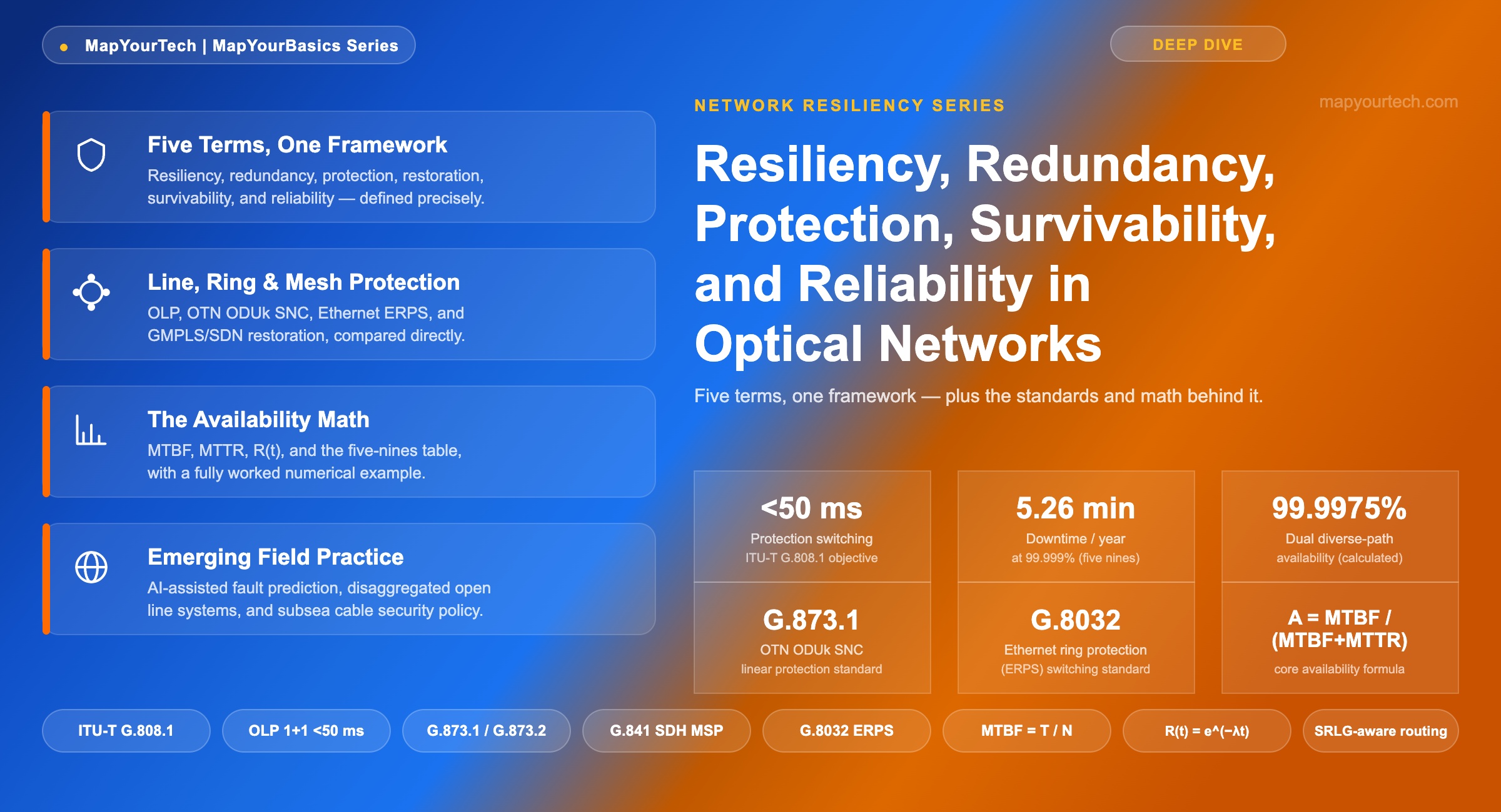
Resiliency, Redundancy, Protection, Survivability, and Reliability in Optical Networks
Five words engineers use almost interchangeably and standards bodies define with precision — here is where they actually diverge, and why the difference changes what you design.
1. Introduction
A fiber cut on a long-haul span does not ask permission before it happens. Backhoes sever ducts, ships drag anchors across submarine routes, and amplifier pump lasers age out of specification at 2 a.m. What separates a network that shrugs off these events from one that generates a customer-facing outage is not a single feature — it is the interaction of five distinct engineering concepts that the industry routinely compresses into one word: "resilience."
Resiliency, redundancy, protection, survivability, and reliability describe different layers of the same problem, and conflating them leads to real design mistakes. A network can have extensive redundancy — spare fiber, spare cards, spare capacity — and still fail to protect a service if the switching logic that activates that spare capacity is missing or misconfigured. A network can have fast, standards-compliant protection switching at the optical layer and still miss its reliability target if the client-layer equipment above it has a Mean Time Between Failures (MTBF) that drags the whole service down. Precision in these terms is not academic pedantry; it changes what an architect specifies, what an operator measures, and what a customer signs in a Service Level Agreement (SLA).
This article works through the five terms in the order an architect actually uses them: what resiliency means as an outcome, how redundancy and protection and restoration are the mechanisms that produce it, how survivability is tested under specific failure scenarios, and how reliability and availability turn all of it into a number that fits in a contract. It then covers the standards framework — ITU-T G.808.1 for generic protection switching, G.873.1 and G.873.2 for the Optical Transport Network (OTN), G.841 for the legacy Synchronous Digital Hierarchy (SDH), and the Ethernet and IP/MPLS mechanisms that now sit alongside them — the architecture of line, ring, mesh, and client-layer protection, the math behind availability targets, and where the field is heading as AI-assisted fault detection and disaggregated open line systems change how fast a network can recover.
The scope is deliberately broad because the five terms span the entire stack: fiber-layer diversity, optical-layer protection, OTN sub-network connection protection, Ethernet ring protection, and IP/MPLS fast reroute all contribute to the same availability number a service provider reports at the end of the measurement period. An engineer who understands only one layer will over-protect some services and under-protect others. The goal here is a working vocabulary and a working set of formulas that hold up whether the network under discussion is a metro ring, a data center interconnect, or a transoceanic submarine cable system.
2. Fundamentals: Five Words, Five Meanings
Start with the outcome and work backward to the mechanisms, because that is the order in which a network actually experiences a failure. A span goes down. Something either keeps the service running or it does not. The word for "kept running" is survivability. The words for "how it stayed running" are redundancy, protection, and restoration. The word for the design philosophy that ties all of it together is resiliency. And the word for the number that shows up in the SLA, independent of any specific failure, is reliability — expressed operationally as availability.
Resiliency: the design intent, not a mechanism
Network resiliency is the capacity of a network to maintain an acceptable level of service in the presence of faults and challenges to normal operation. It is not a single feature a vendor ships; it is an emergent property of how redundancy, protection, and restoration are combined across every layer a service touches — fiber, optical, OTN, Ethernet, and IP/MPLS. A resilient network is one where the failure of any single component, and in well-engineered cases any single shared-risk group, does not translate into a service-affecting outage. Resiliency is the framing an architect uses at the design-review stage, before any specific protection scheme has been chosen.
Redundancy: spare capacity, with no reaction logic of its own
Redundancy is the existence of duplicate or spare resources — a second fiber pair, a spare line card, an idle wavelength, a standby control-plane processor — that could carry traffic if the primary resource fails. Redundancy by itself does nothing: a spare fiber lying dark in the same duct as the working fiber provides no benefit if a backhoe severs both at once, and a spare card sitting in a chassis provides no benefit if nothing detects the primary card's failure and re-points traffic to it. Redundancy is a necessary condition for resiliency, but on its own it is not enough.
Protection: pre-provisioned redundancy with automatic switching
Protection is redundancy that has been wired to a switching mechanism decided in advance of any failure. The backup path, wavelength, or card is already provisioned, and a defined trigger — typically Signal Fail (SF) or Signal Degrade (SD) — causes an Automatic Protection Switching (APS) function to move traffic onto it. Because the decision logic is pre-computed, protection switching is fast: the ITU-T generic protection switching framework in Recommendation ITU-T G.808.1 targets sub-50 millisecond completion for linear and ring schemes, a figure inherited from the original SDH Multiplex Section Protection (MSP) objective in ITU-T G.841 and now carried forward into ITU-T G.873.1 for OTN ODUk linear protection and ITU-T G.873.2 for ODUk shared ring protection.
Restoration: dynamic recovery after the fact
Restoration is the alternative to protection: instead of pre-provisioning a specific backup path, the network computes a new path after a failure is detected, using whatever spare capacity happens to be available at that moment. Mesh restoration, GMPLS-based path recomputation, and SDN-controller-driven rerouting all fall into this category. Restoration trades switching speed for capacity efficiency — recovery typically takes seconds to minutes rather than milliseconds, because a control plane has to detect the failure, compute an alternate route, and signal it end to end — but it can share spare capacity across many possible failure scenarios instead of dedicating it to one.
Survivability: the tested, scenario-specific outcome
Survivability is the property of a network, evaluated against a specific set of failure scenarios, of continuing to deliver a defined grade of service. Where resiliency is the general design philosophy, survivability is what a network planner tests for: "does this topology survive a single fiber cut on any span?" "does it survive the simultaneous loss of both cables in a Shared Risk Link Group (SRLG)?" Survivability analysis is where Shared Risk Group (SRG) protection and geographically disjoint routing enter the picture — a working and protection path that are logically separate but physically routed through the same duct, conduit, or landing station share a risk group, and a single event in that shared location defeats the protection scheme entirely regardless of how fast the switching logic is.
Reliability and availability: the number that goes in the contract
Reliability is the probability that a component or system performs its function without failure over a stated interval, formally R(t) = e−λt for a constant failure rate λ. Availability is the operational, business-facing derivative of reliability: the fraction of time a system is capable of performing its function, incorporating both how often it fails (Mean Time Between Failures, MTBF) and how long it takes to fix (Mean Time To Repair, MTTR). Where reliability describes a single component's failure behavior, availability describes the service the customer actually experiences, and it is availability — expressed in "nines" — that appears in an SLA.
Engineering callout: The standards framework for these mechanisms is layered on purpose. ITU-T G.808.1 defines generic linear and ring protection switching independent of the transport technology. G.873.1 and G.873.2 apply that framework to OTN at the ODUk level. G.841 did the same job for SDH a decade earlier, and Telcordia GR-1230 covers the equivalent SONET ring architectures. Ethernet inherited its own linear (ITU-T G.8031) and ring (ITU-T G.8032, Ethernet Ring Protection Switching) mechanisms rather than reusing the OTN framework directly, because Ethernet's frame-based forwarding model needed its own fault-detection primitives.
Practical Example — Redundancy without protection
A regional carrier lights a second, geographically diverse fiber route between two data centers and leaves it unprovisioned as "emergency spare capacity," activated only by a manual truck roll and a change ticket. When the primary route is cut, the network has redundancy — the spare fiber exists and is physically intact — but it has no protection, because nothing detects the failure and switches traffic automatically. The realistic recovery time is hours, driven by staff availability and change-management process, not by any switching protocol. The fix is not more fiber; it is wiring the existing spare into a G.808.1-compliant 1:1 or 1+1 protection group so the same physical asset produces an automatic, sub-second outcome instead of a manual one.
| Term | Question It Answers | Governing Standard / Mechanism | Time Scale |
|---|---|---|---|
| Resiliency | Is the network designed to keep working under fault conditions in general? | Design philosophy — no single standard | Design-time |
| Redundancy | Does a spare resource exist? | None — a provisioning fact, not a protocol | Static (exists or doesn't) |
| Protection | Will the network switch to that spare resource automatically? | ITU-T G.808.1, G.873.1/G.873.2, G.841, G.8032 | Sub-50 ms to sub-100 ms |
| Restoration | Can the network compute a new path after a failure it did not pre-provision for? | GMPLS, ASON (G.8080), SDN/PCE | Seconds to minutes |
| Survivability | Does the network keep serving customers through this specific failure scenario? | SRLG / disjoint-path analysis (design step) | Evaluated at design time, proven at failure time |
| Reliability / Availability | What fraction of a year is the service actually down? | A = MTBF / (MTBF + MTTR) | Measured over months to years |
Survivability is not the same thing as disaster recovery
It is worth separating survivability from a term it frequently gets merged with in casual conversation: disaster recovery. Disaster recovery is a business-continuity discipline that plans for the loss of an entire site, data center, or region and the process of resuming operations elsewhere, typically over a Recovery Time Objective (RTO) measured in hours. Network survivability, as used in this article, operates one level below that: it is the property of the transport network itself continuing to deliver service through a failure of one or more of its own components — a span, a node, a shared duct — without the applications or data centers riding on top of it ever being aware an event occurred. A network with strong survivability reduces how often disaster recovery procedures need to be invoked at all, because most single-point failures never escalate to the level where a full site failover becomes necessary. Conflating the two leads to a common design gap: an operator with a well-tested disaster recovery runbook for whole-site loss, but no SRLG analysis on the fiber routes connecting those sites, discovers during an actual event that the "diverse" data center interconnect it was counting on for automatic recovery shared a duct crossing with the very link that failed.
Takeaway: Resiliency is the goal, redundancy is the raw material, protection and restoration are the two competing mechanisms that turn that raw material into an automatic response, survivability is what gets tested against specific failure scenarios, and reliability/availability is the number that comes out the other end. Specifying "redundant" in a design document without specifying which of protection or restoration will act on that redundancy leaves the actual recovery behavior undefined.
3. Technical Architecture of Protection
Protection is deployed at four layers that a service can cross on its way from origin to destination: the fiber/physical layer, the DWDM optical layer, the OTN electrical layer, and the client/packet layer (Ethernet or IP/MPLS). Each layer has its own standards, its own switching-time objective, and its own resource trade-off, and a well-engineered network deliberately assigns protection responsibility to the layer best suited to each failure type rather than duplicating it at every layer.
Line protection: 1+1 and 1:1 optical line protection
Optical Line Protection (OLP) operates at the fiber/optical layer and is the fastest form of automatic recovery available, because it requires no digital frame processing — the switch decision is based on optical power loss alone. In 1+1 OLP, the transmitter splits the signal onto both the working and protection fiber simultaneously using a passive optical splitter (a "Y-cable"), and the receiver continuously monitors both incoming signals and selects the better one. Because both paths already carry live traffic, switchover on a fiber cut requires only a receiver-side selection change, typically completed in under 50 milliseconds and often in single-digit milliseconds for hardware-based optical switches. The cost is that 1+1 OLP permanently consumes twice the transponder and fiber capacity for every protected circuit. 1:1 OLP instead keeps the protection fiber idle (or carrying lower-priority extra traffic) until a failure is confirmed, then actively switches the transmitter and receiver onto it — more capacity-efficient, at the cost of a small additional switching delay for the active-path handoff.
| Mechanism | Layer | Typical Switching Time | Extra Traffic Carried | Primary Application |
|---|---|---|---|---|
| 1+1 OLP | Optical (OCh) | <50 ms | No | Long-haul critical spans |
| 1:1 OLP | Optical (OCh) | <100 ms | Optional (low priority) | Regional and metro links |
| Y-cable protection | Transponder | <50 ms | No | Data center interconnect |
| SDH MSP 1+1 (G.841) | SDH section | <50 ms | No | Legacy TDM voice/data |
| 2-fiber BLSR / OBLSR | Ring | <50 ms | Yes, on spare timeslots | Metro rings |
| 4-fiber BLSR | Ring | <50 ms | Yes | High-capacity backbone rings |
| Ethernet ERPS (G.8032) | Ethernet | <50 ms (target) | No (ring, single blocked link) | Metro Ethernet rings |
OTN sub-network connection protection: ODUk-level recovery
Above the wavelength layer, the Optical Transport Network protects traffic at the Optical Data Unit (ODUk) level under ITU-T G.873.1 (linear protection: 1+1 and 1:n Sub-Network Connection, SNC) and G.873.2 (ODUk shared ring protection). G.873.1 defines three monitoring modes that determine how a fault is detected within the protected sub-network: inherent monitoring (SNC/I) relies on the server-layer trail's own defect indications, non-intrusive monitoring (SNC/N) taps the signal without terminating it, and sub-layer monitoring (SNC/S) adds a dedicated tandem connection monitoring (TCM) layer for cases where the sub-network spans multiple operator domains and end-to-end monitoring is not available. Because ODUk cross-connects operate in silicon without IP-style routing lookups, the dataplane switch itself completes in microseconds; the real budget in an OTN protection event is fault detection and Automatic Protection Switching (APS) protocol coordination, not the switch action.
| Mode | How the Fault Is Seen | Where It Applies | Trade-off |
|---|---|---|---|
| SNC/I (Inherent) | Reuses the server-layer trail's own defect indications; no separate monitoring instance | Single-operator domains where the server trail already terminates at both ends of the SNC | Simplest and cheapest, but blind to faults the server layer itself doesn't report |
| SNC/N (Non-intrusive) | Taps and reads the signal's existing overhead without terminating it | Sub-networks where a full trail termination isn't available at the tap point | Good visibility without adding a new monitored trail, but can't originate its own overhead |
| SNC/S (Sub-layer) | Adds a dedicated Tandem Connection Monitoring (TCM) instance spanning just the sub-network | Multi-operator domains where end-to-end path monitoring crosses operator boundaries | Most precise fault localization, at the cost of provisioning and managing an extra monitoring layer |
The APS protocol itself runs in-band, carried in dedicated overhead bytes within the OTN frame (the General Communication Channel, GCC, and associated APS/PCC overhead), the same architectural pattern SDH used with its K1/K2 bytes in the Multiplex Section Overhead. Both ends of a protection group exchange bridge requests and status continuously, not just at the moment of failure, so that a switch request arriving from the far end is validated against a state both nodes already agree on rather than negotiated cold. This is why a single misconfigured node — one running a different default hold-off timer, or interpreting a Signal Degrade threshold differently than its peer — can leave an otherwise standards-compliant protection group unable to complete a clean switch, even though each node individually reports itself as G.808.1-compliant.
Dual-Node Interconnection: protecting against node failure, not just link failure
Every protection scheme discussed so far assumes the working and protection paths fail independently of the node they connect to — but a node failure, not just a span failure, is a real and distinct failure mode. Dual-Node Interconnection (DNI) addresses this by homing a client or a ring segment to two separate nodes rather than one, so that the complete loss of a single node — a chassis failure, a power loss at a site, a software crash that takes an entire shelf offline — does not strand every circuit that happened to terminate there. DNI is common at ring-to-ring or ring-to-mesh interconnection points, where a segment needs to survive not only a fiber cut but the disappearance of the node that was supposed to reroute traffic around that cut. The design trade-off is familiar by now: dual-homing a client to two nodes roughly doubles the port and interconnect cost for that client, in exchange for removing the node itself as a single point of failure — the same parallel-availability math from Section 4 applies, just with "node" substituted for "path."
Client and Ethernet-layer protection
Ethernet services carry their own protection primitives independent of the OTN or DWDM layers beneath them. Link Aggregation (LAG/LACP) bundles multiple physical links into one logical interface and redistributes traffic if a member link fails. Rapid Spanning Tree Protocol (RSTP) blocks redundant paths in a Layer 2 topology and reactivates them on failure, at recovery times that vary with topology size and are typically slower than a dedicated ring protocol. Ethernet Ring Protection Switching (ERPS, ITU-T G.8032) was purpose-built to close that gap: it blocks exactly one link in the ring under normal operation (the Ring Protection Link) and reroutes around a break with an objective in the same sub-50-millisecond class as SDH and OTN ring protection, for ring sizes within the protocol's supported node count. At the IP/MPLS layer, Segment Routing with Topology-Independent Loop-Free Alternate (TI-LFA) and traditional MPLS Fast Reroute pre-compute backup next-hops so that traffic can be rerouted immediately on a link or node failure without waiting for the Interior Gateway Protocol (IGP) to reconverge.
Mesh-based protection and restoration
In mesh topologies, protection resources do not need to be dedicated per working path. Shared Mesh Protection (SMP) pre-computes backup paths but allows multiple working paths to share the same pool of protection capacity, on the statistical assumption that not every protected circuit fails at once — this reduces the capacity overhead relative to 1+1 protection at the cost of a longer switching time, because the shared resource has to be claimed and cross-connected at the moment of failure rather than sitting pre-bridged. Dedicated mesh restoration precomputes a specific backup path per working path but does not activate it until a failure occurs, trading some of SMP's capacity efficiency for a faster, more deterministic recovery. Both are coordinated by a control plane: Generalized Multi-Protocol Label Switching (GMPLS) and the Automatically Switched Optical Network (ASON) architecture defined in ITU-T G.8080 provide distributed signaling for path computation and restoration, while SDN-controlled protection centralizes the same function in a controller with a Path Computation Element (PCE), trading distributed resilience for faster, network-wide optimization and easier multi-layer coordination.
Engineering callout: Multi-layer coordination is not automatic just because every layer has its own protection scheme. If the OTN layer's detection threshold and the IP/MPLS layer's Bidirectional Forwarding Detection (BFD) timer are both tuned to react within the same tens of milliseconds, a single fiber cut can trigger a protection switch at the OTN layer and a re-route at the IP layer simultaneously — both changing the traffic path at once, which can produce a longer total outage than either mechanism acting alone. The hold-off timer and Wait-to-Restore (WTR) timer parameters defined in G.808.1 exist specifically to sequence this: the lowest, fastest layer gets first attempt, and higher layers only act if that attempt does not clear the fault within its allotted window.
4. Design Considerations and Availability Math
Every protection architecture decision eventually gets reduced to a single question from finance or from the customer: what availability number does this buy, and what does it cost? Answering that question requires four formulas that convert component-level reliability data into a service-level percentage, and a clear-eyed accounting of when redundancy actually behaves as independent, parallel protection instead of two paths that share the same failure mode.
Practical Example — From component data to an availability percentage
A carrier-grade optical switch reports a typical MTBF in the range of 25,000–35,000 hours from field reliability data, with an MTTR of roughly 2 hours for a card swap by an on-site technician (measured / vendor-reported range, not a universal constant). Taking 30,000 hours as a working midpoint: A = 30,000 / (30,000 + 2) = 0.999933, or 99.9933%. Applying the unavailability formula, U = (1 − 0.999933) × 525,600 ≈ 35 minutes per year — a single unprotected switch sits between the "four nines" and "five nines" tiers on its own, before any protection scheme is added on top of it.
What redundancy actually buys, in numbers
The value of adding a second, independent path is best seen through the parallel-reliability form of the availability formula: if a single path has unavailability (1 − A), and a second, statistically independent path has the same unavailability, the probability that both fail at the same moment is the product of the two unavailability figures, not their sum. A single span at 99.5% availability has an annual downtime of roughly 43.8 hours. Two genuinely independent, diversely routed spans at that same 99.5% figure combine to 1 − (0.005)2 = 99.9975% — a jump of more than two nines from a single added path, because both paths have to fail during the same window for the service to be down. This is a calculated, theoretical-limit figure that assumes true independence; it is also exactly the assumption that Shared Risk Link Group (SRLG) violations quietly break. A "diverse" second path that shares a duct, a bridge crossing, or a submarine cable landing station with the first path is not statistically independent at that shared point, and the parallel-reliability math no longer applies across that segment — which is precisely why survivability analysis, covered in Section 2, treats SRLG-aware routing as a separate design step from simply provisioning a second circuit.
The other half of the math: series reliability along the working path itself
Redundancy math gets the attention because it is where the interesting multiplication happens, but it only tells half the story. Before any protection scheme is even considered, the working path a service travels is already a series chain of individual components — transponders, amplifiers, ROADM add/drop stages, patch panels, connectors — and series reliability combines by multiplying each component's availability together, which only ever pulls the total down: Apath = A1 × A2 × … × An. A path with ten components each individually at 99.995% availability — a respectable figure for carrier-grade hardware in isolation — combines to 0.9999510 ≈ 99.95%, which has already dropped a full nine below any single component's own rating before protection enters the picture at all. This is the reason long-haul and submarine systems, which can carry dozens of amplifiers in series over a single unprotected span, cannot rely on component quality alone to hit a five-nines target: the series-chain effect erodes availability faster than component-level reliability improvements can claw it back, and protection or restoration at the path level becomes the only lever left that actually moves the number in the right direction.
| Component | Typical MTBF Range (hours) | Typical MTTR (hours) | Implied Availability |
|---|---|---|---|
| Optical amplifier (EDFA) | 200,000–500,000 | 3–4 | >99.999% |
| Coherent transponder | 25,000–40,000 | 1.5–2 | ≈99.99–99.995% |
| Optical switch / ROADM module | 25,000–35,000 | 2–3 | ≈99.99% |
| Router / packet switch | 15,000–30,000 | 2–4 | ≈99.97–99.99% |
Two things are worth stating plainly about that table. First, the ranges are field-reported and vary by vendor, generation, and operating environment — they are starting points for a budget calculation, not specification-grade numbers to design a contract around. Second, the amplifier figure looks the most impressive in isolation precisely because amplifiers are simpler, more numerous, and individually less likely to fail than actively switched or processed elements like transponders and routers — but a long-haul path with fifteen amplifiers in series still multiplies that high individual reliability fifteen times over, which is exactly the series-chain effect described above.
The core-to-edge availability cascade
Real networks do not apply one availability target uniformly across their topology; they apply a cascade, and that cascade is a deliberate economic outcome rather than an oversight. Three constraints compete for the same budget at every layer of a network: price, reliability, and coverage. Improving all three at once — cheaper, more reliable, and available everywhere — is not an engineering option available at any layer; a design can push two of the three in a favorable direction, and the third absorbs the cost. A network core, aggregating the traffic of every customer behind it, justifies full mesh or ring topology and N+1 or N+2 redundant paths, which is why core targets commonly sit at 99.999% (five nines). Move outward and the number of independent parallel paths available to any one circuit drops, and the achievable target drops with it — not because the equipment got worse, but because the traffic volume at each successive layer stops justifying the same density of protection.
| Network Position | Typical Target | Typical Protection Density |
|---|---|---|
| Core / backbone | 99.999% | Full mesh or N+1/N+2 diverse paths |
| Regional / aggregation | 99.99% | Ring or partial-mesh protection |
| Metro / access distribution | 99.95%+ | Ring-protected in dense areas, thinner elsewhere |
| Last-mile / single-fibered edge | 99.9% or lower | Often single-homed by deliberate economic trade-off |
The same series-reliability effect from earlier in this section operates at the scale of an entire network, not just a single path's components. Even a service engineered with a zero-tolerance design intent for downtime — a safety-of-life or emergency-routing function, for example — is still carried on the same physical layer as every other service, and its achievable availability still converges toward whatever ceiling that underlying core and access infrastructure can actually deliver. A target written into a policy document above the transport layer cannot manufacture physical-layer capacity that was never built beneath it; if the access node serving that function is single-fibered, the function inherits that node's realistic ceiling regardless of how the service above it was specified. This is also why the tiered service mapping in Table 8 and the network-position cascade in Table 5 compound rather than substitute for each other: a Tier 4 best-effort service riding on a single-fibered edge node inherits the lower ceiling of its physical location before any service-class decision about that circuit is even made.
| Availability | Downtime / Year | Typical Context |
|---|---|---|
| 99% | 87.6 hours | Best-effort access, generally unacceptable for carrier services |
| 99.9% | 8.76 hours | Acceptable for non-critical enterprise links |
| 99.99% | 52.56 minutes | Enhanced reliability, most commercial transport services |
| 99.999% ("five nines") | 5.26 minutes | Carrier-grade, the standard reference point for protected transport |
| 99.9999% ("six nines") | 31.5 seconds | Mission-critical, e.g. financial trading transport |
| 99.99999% ("seven nines") | 3.15 seconds | Rare, reserved for the most availability-sensitive applications |
Engineering callout: Cost scales faster than availability does. Moving a single-path service from 99.5% to a genuinely diverse dual-path design at 99.9975% is usually the highest-value protection investment available, because it removes the single point of failure entirely. Moving an already-protected service from five nines to six nines typically means adding protection at a second layer (for example OTN SNC protection on top of existing DWDM OLP) for a service that was already recovering in under 50 ms — a real but much smaller improvement in customer-visible downtime, purchased at a much higher relative cost.
5. Implementation and Operations
Specifying a protection scheme on paper and getting it to behave correctly in a live, multi-vendor network are different problems. Three operational parameters determine whether a protection group behaves the way its data sheet promises: the switching trigger, the hold-off timer, and the revertive behavior.
Switching triggers: Signal Fail and Signal Degrade
Protection switching is initiated by one of a small set of defined conditions. Signal Fail (SF) covers hard failures — loss of signal, loss of frame, a Bit Error Rate (BER) exceeding a fixed threshold typically around 10−3 — and is intended to trigger a switch immediately. Signal Degrade (SD) covers soft failures, where the signal is still present but its error rate has crossed a lower threshold, often around 10−5 to 10−6, indicating the path is on a trajectory toward failure. SD-triggered switches exist to move traffic before a marginal path actually goes down, but they need a longer persistence check than SF to avoid reacting to transient noise. Administrative triggers — forced switch and manual switch commands issued from the craft interface or the network management system — sit alongside these automatic triggers for planned maintenance and testing.
Hold-off timers and Wait-to-Restore
The hold-off timer is the delay a protection scheme waits after detecting a fault before actually switching, and its main job is multi-layer sequencing: giving a lower, faster layer (optical or OTN) the chance to clear the fault before a higher layer (Ethernet or IP/MPLS) commits to its own re-route, exactly the coordination shown in Figure 3. Getting the hold-off timer wrong in either direction has a real cost — set too short, and two layers switch on the same event, potentially producing a longer combined outage than either layer switching alone; set too long, and the network sits in a failed state waiting for a lower layer that was never going to recover. The Wait-to-Restore (WTR) timer governs the return trip: once the original working path is confirmed healthy again, a revertive protection scheme waits out the WTR interval, commonly five to twelve minutes, before switching traffic back, to avoid "flapping" between working and protection paths on an intermittent fault.
Revertive versus non-revertive switching
A revertive protection group automatically returns traffic to the original working path once it is confirmed stable past the WTR interval, keeping the "designated" working path consistent for operational and troubleshooting purposes. A non-revertive group leaves traffic on whichever path it switched to, treating both paths as operationally equivalent going forward. Revertive behavior is the more common default because it keeps documented traffic engineering and capacity planning aligned with the physical network, but non-revertive behavior avoids a second, unnecessary switching event on a path that has already proven itself stable.
Practical Example — A hold-off timer misconfiguration
An operator deploys OTN ODUk SNC protection (G.873.1) with a default 100 ms hold-off timer, on top of an IP/MPLS layer running Bidirectional Forwarding Detection (BFD) tuned to a 50 ms detection interval for fast reroute. On a fiber cut, the IP layer detects the failure and reroutes before the OTN layer's hold-off window has even expired, because the BFD timer is faster than the hold-off delay meant to give the lower layer first attempt. The OTN protection switch then fires a moment later on the same event, moving the already-rerouted IP traffic onto a newly cross-connected ODUk path and forcing a second, avoidable disruption. The fix is to set the client-layer detection timer longer than the transport-layer's combined detection-plus-hold-off-plus-switch budget, not the reverse.
Testing, validation, and multi-vendor interworking
Protection groups need to be validated against the actual failure modes they claim to cover, not just against a clean pull-the-fiber test. A credible test plan exercises Signal Fail, Signal Degrade, forced switch, manual switch, lockout of protection, and — for ring topologies — a dual-failure scenario to confirm the ring correctly refuses to attempt an unsafe switch rather than failing silently. Lockout of protection is worth calling out specifically: it is an administrative command that disables automatic switching to a protection path entirely, used while that path is itself under maintenance, and its entire purpose is to prevent the network from "protecting" traffic onto a path that is not actually safe to carry it — a test plan that never exercises lockout has never confirmed the network fails safely during its own maintenance windows, which is precisely when a second, unrelated fault is statistically most likely to compound the risk. Multi-vendor interworking is a recurring source of field issues: the G.808.1 framework standardizes the protocol and the timing objectives, but APS byte encoding and default timer values have historically varied enough between vendor implementations that mixed-vendor protection groups warrant explicit interoperability testing before they carry live traffic, rather than an assumption that standards compliance alone guarantees a clean handoff.
Practical Example — A ring correctly refusing a second switch
A metro Ethernet ring running ERPS already has one span down and is correctly carrying all traffic around the ring the long way via its Ring Protection Link. A second, unrelated span then fails elsewhere on the same ring. A ring protection scheme designed for single-failure recovery has no safe path left to offer — attempting to "protect" against the second failure would require breaking the ring into two disconnected segments, silently dropping every node between the two failures rather than fixing anything. Correct behavior is for the ring to recognize the dual-failure condition and simply accept the segmentation as the least-bad outcome, rather than attempting an undefined switch that could black-hole traffic across the whole ring. This is exactly the scenario a dual-failure test case is meant to catch before it happens on a live ring: confirming the protocol fails predictably, not confirming it somehow still delivers zero downtime, which single-fault ring protection was never designed to guarantee.
6. Performance, Monitoring, and Analysis
A protection scheme that works in isolation still needs continuous monitoring to confirm it is behaving as designed, because a protection group with a stuck bridge, a mis-provisioned protection path, or a receiver that silently stopped monitoring the standby signal fails exactly when it is needed and not a moment before.
Switching-time performance by mechanism
The chart below compares typical switching-time objectives across the mechanisms covered in Section 3. These are standard-specified or vendor-targeted objectives, not measured results from any single deployment, and actual field performance depends on fault-detection configuration, node count (for rings), and hold-off timer settings.
Optical Performance Monitoring and proactive detection
Optical Performance Monitoring (OPM) — continuous measurement of per-channel power, Optical Signal-to-Noise Ratio (OSNR), and, in coherent systems, pre-FEC Bit Error Rate — is what turns Signal Degrade from a theoretical trigger into a usable one. A channel whose pre-FEC BER is climbing but has not yet crossed the SD threshold is a candidate for proactive maintenance, not automatic switching, and distinguishing between the two requires the trend data OPM provides rather than a single instantaneous reading. Automated dashboards that correlate OSNR, BER, and power levels across a route let operations teams act on a degrading channel before it crosses into a customer-visible event, shifting effort from reactive fault response toward planned intervention.
Engineering callout: Field research on AI-assisted operations describes predictive maintenance models built on anomaly detection and time-series forecasting that flag likely failures ahead of a hard fault, with several published case studies reporting reduced false-alarm rates and shorter restoration windows in trials (published research findings, evidence class: study-reported, results vary by dataset and are not a universal deployment figure). Separately, broader enterprise AI adoption surveys report that most large organizations have moved AI tools into production somewhere in their operations, though the same surveys note that a much smaller share have restructured workflows around AI deeply enough to change how a team actually operates day to day (industry survey data, general enterprise AI adoption — not specific to network operations). The practical framing that has held up in telecom operations is "human-in-the-loop": AI-based anomaly detection recognizes patterns and recommends or pre-stages a response, but engineers still validate major protection and restoration actions, because a model trained on historical fault patterns has no contextual understanding of a failure mode it has not seen before.
Measuring availability in the field: from theory to logged seconds
The availability formula in Section 4 is a planning tool; measuring what a network actually delivered requires the error-performance parameters standardized in ITU-T G.826 and G.828. Three counters do the work: an Errored Second (ES) is any one-second interval containing at least one bit error; a Severely Errored Second (SES) is a one-second interval whose error ratio exceeds a defined threshold, generally 10−3; and an Unavailable Second (UAS) begins once ten consecutive SES events have occurred and continues until ten consecutive seconds pass with no SES — a deliberate hysteresis that stops a network from flapping between "available" and "unavailable" on a single noisy second. Annual UAS count is the field-measured counterpart to the calculated unavailability figure in Table 6: where Table 6 answers "what should this network's downtime be, given its component MTBF and MTTR," a year of logged UAS answers "what was this network's downtime, given what actually happened to it," and the gap between the two numbers is usually the most useful diagnostic an operations team has for finding under-performing links before a customer escalation does.
Troubleshooting a protection event after the fact
Post-event analysis on a protection switch should reconstruct three timestamps: when the fault was first detectable at the physical layer, when the protecting layer's APS protocol actually initiated the switch, and when traffic was confirmed restored end to end. The gap between the first and second timestamps is fault-detection latency; the gap between the second and third is switch-and-verify time. Systems that log only "protection switch occurred" without these component timestamps make it difficult to tell whether a slower-than-expected recovery came from a detection-threshold problem, a hold-off timer misconfiguration, or an actual switching-hardware delay — three problems with three different fixes.
7. Comparison and Selection Criteria
Protection and restoration are not competing standards to choose between once and for all — they are complementary tools that a well-designed network applies selectively, by service class, and the correct mix is a cost decision as much as a technical one.
| Aspect | Protection | Restoration |
|---|---|---|
| Switching time | Sub-50 ms to sub-100 ms (pre-computed) | Seconds to minutes (computed after failure) |
| Resource model | Pre-allocated, dedicated or pre-bridged | Shared spare capacity, claimed on demand |
| Capacity efficiency | Lower — capacity sits idle until needed | Higher — one spare pool covers many scenarios |
| Predictability | Deterministic outcome and timing | Outcome depends on network state at failure time |
| Best fit | Single circuits with hard SLA timing commitments | Large mesh networks with many possible failure combinations |
Most carrier networks run both at once, assigned by service class rather than chosen exclusively. A four-tier framework that maps cleanly onto the protection mechanisms in Section 3 looks like this in practice:
| Service Tier | Typical Mechanism | Target Recovery | Representative Use Case |
|---|---|---|---|
| Tier 1 — Mission-Critical | 1+1 OLP + client-layer 1+1 | <50 ms | Financial trading transport, disjoint-path submarine links |
| Tier 2 — Premium Transport | 1+1 or 1:1 OLP, ODUk SNC 1+1 | <50–100 ms | Data center interconnect, enterprise private line |
| Tier 3 — Standard Commercial | Ring protection (ERPS / OBLSR) | <50–300 ms | Metro Ethernet and regional aggregation |
| Tier 4 — Best-Effort | Mesh restoration or unprotected | Seconds–minutes, or none | Bulk transfer, non-time-sensitive backup traffic |
Environment matters as much as service class. Submarine systems favor disjoint-path protection and Shared Risk Group avoidance over raw switching speed, because a repair ship can take days to reach a fault site and the priority is making sure a single cable event cannot take down every route to a region at once. Dense urban metro rings favor Ethernet or OTN ring protection for its space and cost efficiency over 1+1 linear schemes. Data center interconnect favors 1+1 or Y-cable protection at the transponder level, where the priority is deterministic sub-50-millisecond recovery for a small number of very high-capacity circuits rather than resource sharing across many paths.
Over-protecting is a real failure mode, not a safe default
The instinct to protect everything at every layer, "just to be safe," has a cost that compounds the same way the parallel-availability benefit does — except in the wrong direction for the budget. Stacking 1+1 protection at the optical layer, 1+1 SNC at the OTN layer, and a redundant IP/MPLS path for the same circuit does not multiply the availability benefit three times over; past a certain point it mostly multiplies cost and operational complexity, because the weakest unprotected link in the chain (a shared power feed, a single building entrance, a common management network) usually dominates the achievable availability regardless of how many transport layers are separately protected above it. The multi-layer coordination problem from Section 3 gets worse, not better, with each additional protection layer stacked on the same circuit, since every layer added is another hold-off timer that has to be correctly sequenced against the others. The disciplined version of "protect everything" is closer to "identify the layer that gives the best availability improvement per dollar for this specific service, protect there, and let the layers above and below it stay simple" — which is the same logic Routed Optical Networking architectures apply when they deliberately remove redundant protection from the optical layer for services the IP layer is already protecting.
Shared responsibility: where the network's committed availability ends and yours begins
A publicly available communications network commits to an availability figure for the network itself — not a guarantee automatically extended to every third-party system that happens to depend on that connectivity. This distinction matters most for organizations operating infrastructure where continuous connectivity is an operational precondition rather than a convenience: transportation signaling, hospital systems, industrial control, financial settlement, and comparable critical operations. Per the cascade in Section 4, the access-layer commitment at any specific site is very often in the 99.9%-to-99.95% range rather than five nines, simply because of where that site sits in the topology. If an organization's own tolerance for downtime is tighter than that commitment, closing the gap is the responsibility of the organization consuming the connectivity, not the network delivering it — the network was never designed, priced, or contracted to deliver more than the figure it publishes.
Engineering callout — ingredients for resiliency at the point of consumption:
Genuine physical path diversity. Two circuits are redundant only if they share no duct, bridge crossing, landing station, or Shared Risk Link Group anywhere along their route — the SRLG discipline from Section 2 applies as much to a site's own dual-homed access as it does to a carrier's backbone.
Technology and provider diversity, not path diversity alone. Two fiber circuits from the same operator can still share a common-mode failure — a control-plane software defect, a shared upstream transit provider, a single management system — that no amount of physical separation protects against. Pairing a fixed circuit with an independent wireless or satellite failover path, or contracting two separate operators, protects against failure modes that stay entirely within one operator's control plane.
Power resiliency matched to the network's own. A diverse fiber path terminating in equipment that shares a single, non-backed-up power feed is not actually diverse at the point that matters; local battery and generator backup at the site needs to at least match the runway the network's own backup power provides at its access nodes.
Protection switching matched to actual failure modes, using the mechanisms from Section 3 rather than assuming a generic backup line behaves like a standards-based 1+1 or 1:1 protection group with a defined switching-time objective.
Fail-safe application design. No finite availability figure reaches 100%, so the operational system riding on top of the network needs a tested behavior for the connectivity-loss case itself — degrading to a safe local mode rather than failing in an undefined way — because reducing the probability of an outage to near zero is a different design problem than reducing the consequence of an outage to near zero.
None of this changes the arithmetic from Section 4: a network segment committed at 99.95% will, by definition, still produce close to 4.4 hours of downtime somewhere across a year, and no amount of downstream engineering changes that published figure. What downstream engineering changes is who that downtime affects and how visibly. An organization that has built its own diverse, technology-independent, fail-safe path against a known, disclosed figure has already treated that network's downtime window as a design input. An organization that has not treats the same, contractually disclosed window as a surprise — and which of those two outcomes occurs is decided long before any specific outage happens.
What "bulletproof" actually requires, and why nobody builds it
"Bulletproof" is a common shorthand for a resiliency target, and it is worth being precise about what approaching it would actually take, because the honest answer explains why almost no real deployment goes that far. The reliability formula from Section 4, R(t) = e−λt, makes the ceiling explicit: for any finite failure rate λ greater than zero and any nonzero time interval t, R(t) is always strictly less than one. No finite architecture reaches exactly 100% availability forever; "bulletproof" is a direction to keep moving in, not a destination any design fully arrives at.
A cost-no-object version of the ingredient list from the previous section looks roughly like this: three or more genuinely independent access paths, each on different physical infrastructure, a different access technology (fixed fiber, fixed wireless, satellite), and a different operator with no shared upstream transit; power backup at every active element along every path, sized for a worst-case outage duration measured in days rather than hours, with independent generation rather than battery alone at the most critical sites; geographic separation wide enough that no single regional event — a storm system, a regional power grid failure, a single jurisdiction's regulatory action — can degrade more than one path at once; and an independently operated control plane and management system for each path, so a software defect or a compromised credential in one operator's systems cannot cascade into the others.
Each ingredient on that list is individually achievable; what makes the complete stack rare is that the cost of closing the remaining gap grows much faster than the gap itself shrinks. This is the "pick two of three" economics from the core-to-edge cascade in Section 4, replayed at the scale of a single site instead of a whole network: each additional increment of availability tends to require eliminating an entire class of shared dependency — a shared operator, a shared power grid, a shared geography — rather than simply adding one more redundant component, and eliminating a class of dependency is a step change in cost, not a proportional one.
| Tier | Typical Requirement to Reach It | Relative Engineering Cost |
|---|---|---|
| Baseline (≈99%) | Single path, best-effort repair | Reference point |
| Standards-protected (99.9–99.95%) | Dual path with standards-based protection switching (Section 3) | Moderate increase |
| Carrier-grade (99.99%) | Ring or mesh protection, SRLG-aware diverse routing | Substantial increase |
| Five nines (99.999%) | Full path, technology, and provider diversity, with matched power backup | Large increase |
| Beyond five nines (99.9999%+) | Independent control planes, regional-scale geographic separation | Very large increase, often disproportionate to the marginal operational benefit |
Engineering callout: The practical trade-off "bulletproof" thinking tends to skip past is that pursuing it is a decision to spend against a target that has no defined endpoint, since Table 9's ladder does not terminate. The more tractable version of the question is not "how do I make this bulletproof," it is "what downtime can this specific operation actually tolerate before the consequence becomes unacceptable, and what is the minimum combination of the ingredients above that reliably stays under that number." That reframing is what turns an open-ended, ever-escalating cost target into a bounded engineering problem — and it is the same discipline behind the "over-protecting is a real failure mode" point earlier in this section: past the tier a specific service actually needs, additional resiliency spend buys shrinking operational benefit for growing operational complexity, on both sides of the shared-responsibility boundary.
Takeaway: There is no universally "best" protection mechanism — only the mechanism that matches a given service's timing requirement, capacity budget, and failure-scenario exposure. The selection question is never "protection or restoration," it is "which combination, assigned to which layer, for which service class."
8. Future Directions
Three developments are reshaping how resiliency gets engineered: physical-layer disaggregation, AI-assisted operations, and a sharp rise in policy attention on submarine cable security.
Disaggregated and open line systems
As networks move toward disaggregated architectures — transponders, open line systems, and ROADMs sourced from different vendors and interconnected through standardized interfaces such as OpenROADM — protection and restoration logic increasingly has to be coordinated across vendor boundaries rather than inside a single integrated platform. This pushes more of the coordination work described in Section 3 into the SDN controller and its Path Computation Element, since no single vendor's embedded control plane can see the whole disaggregated topology. Routed Optical Networking architectures, which move protection responsibility onto the IP/MPLS layer for packet services while reserving circuit-style protection for private-line traffic, follow the same logic: fewer, better-coordinated protection domains instead of duplicated protection stacked at every layer independently.
It is worth stating directly that this rising complexity has not come at the expense of reliability, even though intuition suggests it should. Networks built on dedicated circuit-switched hardware with infrequent firmware changes were simpler to reason about, but they also carried a fraction of today's functionality and interconnected far fewer independent systems. The shift to fully abstracted, virtualized, all-packet cores has multiplied the number of interacting platforms involved in delivering any single service, to the point that operating them end to end is now often a specialist function in its own right — and availability has continued to improve alongside that complexity, not despite it, because each additional layer of abstraction has also been an additional layer where protection, monitoring, and automated restoration could be applied. Complexity and reliability are not opposed by nature; a network only fails to improve on both at once when protection architecture at each new layer is treated as optional rather than designed in from the start.
AI-assisted fault prediction and self-healing operations
Telecom operations teams report a shift toward AI systems that correlate patterns across throughput, latency, and handover or protection-switching metrics rather than reacting to individual alarms in isolation (industry trend reporting, evidence class: reported trend, not a universal deployment figure). The distinction operators keep making is that self-healing is not the same as autonomous: pattern recognition and automated remediation handle routine, previously-seen fault signatures, while unfamiliar or ambiguous failures still route to an engineer, because a model trained on historical fault data has no way to validate a scenario it has never encountered. Where this most directly touches the five terms in this article is restoration: AI-assisted path computation can shrink the seconds-to-minutes restoration window described in Section 3 by pre-ranking likely backup paths based on real-time network state, without changing the underlying protection-versus-restoration trade-off.
Submarine cable security becomes a policy issue, not just an engineering one
Survivability design for submarine systems has always centered on physical diversity and Shared Risk Group avoidance, but that design principle has been reinforced by government policy through 2025 and 2026 rather than left purely to operator discretion. NATO's Critical Undersea Infrastructure Network, a civil-military coordination body established in February 2024, took on operational weight after a string of Baltic Sea cable and pipeline incidents through late 2023 and 2024; in direct response, NATO launched the multi-domain "Baltic Sentry" patrol mission in January 2025, deploying frigates, maritime patrol aircraft, and naval drones to the region (reported policy development, NATO public statements). The European Union's Action Plan on Cable Security, published February 2025, separately committed to an Integrated Surveillance Mechanism and a dedicated Baltic Sea regional test bed. Reported subsea cable incidents continued into 2026, including damage to cables in the Baltic and Central Baltic Sea region in January 2026 (reported incidents, cited in U.S. legislative findings). In the United States, bicameral legislation — the Senate's Strategic Subsea Cables Act of 2026 (S.3249) and its House companion (H.R.8069) — advanced through the Senate Foreign Relations Committee in January 2026 and, as of mid-2026, remained pending full chamber votes; its provisions call for sanctions against parties who sabotage undersea infrastructure and increased U.S. engagement with the International Cable Protection Committee (reported legislative status, current as of mid-2026 — verify current status before citing in time-sensitive contexts, since a bill's committee-passage stage is not enactment). Industry tracking from TeleGeography places the global submarine cable count at more than 600 active and planned systems as of 2026, carrying over 1.5 million kilometers of cable in service and an estimated majority of international data traffic (industry tracking data, dated to its source). For network architects, the practical effect is that disjoint-path and Shared Risk Group analysis for submarine-dependent routes now needs to account for geopolitical risk concentration, not only physical routing, when two "diverse" cables land in ports or transit chokepoints that face correlated exposure.
Elastic and quantum-safe protection
Elastic optical networking, which allocates spectrum in narrower flexible-grid slices rather than fixed 50 or 100 GHz channels under ITU-T G.694.1, gives restoration algorithms narrower, finer-grained spectrum options when recomputing a backup path after a failure, since a partially-available spectrum gap that could not fit a fixed-grid channel may still fit a narrower flexible-grid allocation. Separately, as quantum computing's long-term threat to current public-key cryptography drives broader adoption of quantum-safe key exchange, protection-switching coordination channels — the APS byte overhead and GCC channels described in Section 3 — are an active area of research for post-quantum key distribution integration, particularly for submarine systems whose multi-decade service life will outlast the current cryptographic baseline.
9. Reference Section
The working vocabulary from this article, condensed: resiliency is the design outcome; redundancy is spare capacity with no switching logic of its own; protection is redundancy wired to a pre-computed, automatic switch, standardized generically in ITU-T G.808.1 and applied to OTN in G.873.1/G.873.2, to SDH in G.841, and to Ethernet rings in G.8032; restoration is dynamic path recomputation after a failure, coordinated through GMPLS, ASON, or an SDN controller; survivability is the scenario-tested result, defeated by Shared Risk Link Group violations regardless of switching speed; and reliability/availability is the measured or calculated output — A = MTBF/(MTBF+MTTR) — that turns all of the above into the number that appears in a contract.

Optical Communications & Network Automation Expert | Author of 3 Books for Optical Engineers | Founder, MapYourTech
Optical networking engineer with nearly two decades of experience across DWDM, OTN, coherent optics, submarine systems, and cloud infrastructure. Founder of MapYourTech. Read full bio →
Follow on LinkedInRelated Articles on MapYourTech