
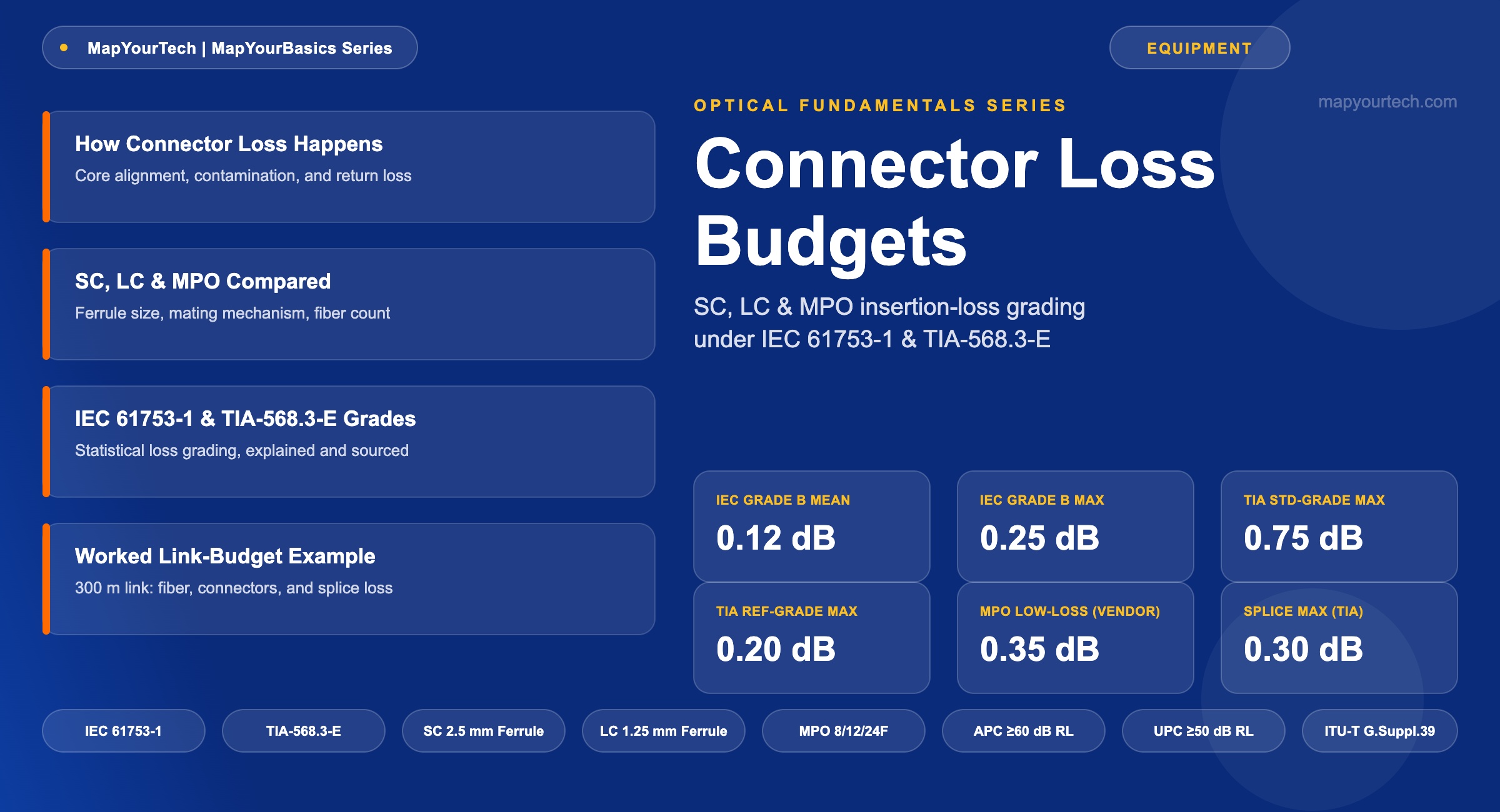
Connector Types and Their Loss Budgets: SC, LC, MPO
A field reference for SC, LC, and MPO connector insertion loss, grounded in IEC 61753-1 and TIA-568.3-E grading, with a worked link-budget example.
1. Introduction
A single mated connector pair on a single-mode link can cost anywhere from 0.10 dB to 0.75 dB, depending on the grade of the connector and how it was terminated. On a short data-center jumper that range barely registers. On a 44-channel DWDM span running close to its power budget with a dozen patch points between transmitter and receiver, the same range is the difference between a link that passes commissioning and one that fails margin by a fraction of a decibel.
This reference covers the three connector families an optical engineer meets daily — SC, LC, and MPO/MTP — and grounds their loss numbers in two sources that actually define them: IEC 61753-1, which grades single-fiber connectors by statistical attenuation performance, and ANSI/TIA-568.3-E, the current (2022) edition of the premises optical fiber cabling standard that sets the loss limits used in field certification. It closes with a worked link-budget calculation and a look at where connector form factors are heading as 2026 data centers push toward 800 Gbps and 1.6 Tbps interconnects.
Who this is for: technicians building loss budgets for patch panel and trunk cabling, and network engineers who need connector numbers they can defend in a design review rather than a rule of thumb pulled from memory.
2. How Connector Loss Happens
Every fiber connector does the same physical job: it holds a glass fiber inside a precision ferrule and presses that ferrule against a matching one so the two cores line up closely enough for light to cross the gap with minimal loss. Insertion loss is the ratio of output power to input power expressed in decibels, IL = −10 log₁₀(Pout/Pin), and everything that keeps the two cores from lining up perfectly adds to that number.
Two categories of misalignment drive the loss. Intrinsic factors are built into the fiber itself — core diameter mismatch, numerical aperture mismatch, and core eccentricity relative to the outer cladding — and a connector cannot correct for them. Extrinsic factors come from the termination and the mating event: lateral offset between the two cores, angular tilt at the end faces, an air gap where the ferrules do not make full physical contact, and contamination such as dust or oil film on the polished surface. A single fingerprint on an end face can add several tenths of a decibel and is the most common cause of a connector that measures worse than its rated grade.
Because these tolerances are statistical rather than fixed, connector performance is graded probabilistically. Return loss — the fraction of light reflected back toward the source at the mated interface — follows the same logic. A flat-polished end face reflects roughly −14 dB back toward the laser; a Physical Contact (PC) polish improves that to roughly −40 dB by curving the end face to eliminate the air gap; Ultra Physical Contact (UPC) extends the polish further for roughly −50 dB; and Angled Physical Contact (APC), which polishes the end face at an 8° angle so reflected light escapes into the cladding instead of returning down the fiber, typically reaches −60 dB or better. These are industry-consensus figures rather than a single standard's mandate, and they explain why APC connectors — identifiable by their green housings — dominate PON, CATV, and other reflection-sensitive links, while UPC (blue) remains the default for most enterprise and data-center fiber. A deeper treatment of the reflection mechanism and its system-level impact is in the MapYourTech guide to optical return loss.
Takeaway: Insertion loss and return loss are measuring two different failure modes of the same mechanical contact — how much light gets through, and how much of what does not get through comes back toward the source. A connector spec sheet that lists only one of the two is giving half the picture.
3. SC, LC, and MPO: Physical Differences
The three connector families differ in ferrule geometry and fiber count, not in the underlying physical-contact principle described above.
SC — Subscriber Connector
SC uses a round 2.5 mm ceramic ferrule and a push-pull mating mechanism with no twist required. It was the volume standard for single-fiber DWDM and telecom patch panels through the 2000s and remains common on legacy line cards and test equipment. Its larger ferrule gives it slightly better mechanical stability during repeated matings than LC, at the cost of roughly double the panel footprint.
LC — Lucent Connector
LC halves the ferrule to 1.25 mm and adds an RJ-style latch, doubling patch-panel density against SC in the same rack space. Because the ferrule physics are identical to SC's — same ceramic material, same physical-contact principle — an LC and an SC connector of the same polish grade deliver essentially the same insertion and return loss; the difference is purely mechanical and dimensional. LC is the default single-fiber interface on modern pluggable transceivers, as detailed in the MapYourTech guide to pluggable optical transceivers, and duplex LC pairs are keyed so the transmit and receive fibers cannot be crossed by accident.
MPO/MTP — Multi-Fiber Push-On
MPO (the generic term; MTP is a specific manufacturer's trademarked version of the same interface) replaces the single round ferrule with a rectangular MT ferrule that holds an aligned array of fibers — commonly 8, 12, or 24 per connector — and uses guide pins rather than a spring-loaded round ferrule to achieve alignment across the whole array in one mating action. That single mating event connects every fiber in the array simultaneously, which is what makes MPO the interface of choice for parallel-optics transceivers such as SR4 and DR4 and for high-fiber-count trunk cabling between patch panels. TIA-568.3-E defines five polarity methods (A, B, C, and the newer universal U1/U2) to keep transmit and receive fiber pairs correctly mapped end to end across an MPO-based channel — a topic covered in more depth in the MapYourTech guide to QSFP technology, which also covers the CS connector as a related high-density alternative.
Takeaway: SC and LC share identical ferrule physics at different scales, so their loss numbers are interchangeable by grade. MPO is a different mechanism entirely — array alignment via guide pins — and its loss budget has to be evaluated per fiber channel within the connector, not as a single number for the whole plug.
4. Loss Budgets by Standard
IEC 61753-1, Fibre Optic Interconnecting Devices and Passive Components — Performance Standard, defines attenuation grades for randomly mated single-fiber connectors under the assumption of worst-case alignment. A connector graded to a given level is expected to meet or exceed that attenuation performance with at least 97 percent probability when mated to another connector of the same grade — it is a statistical guarantee, not a per-unit measurement. Grade A is reserved for future definition; Grade B specifies a mean loss of 0.12 dB and a 97th-percentile maximum of 0.25 dB; Grade C specifies a mean of 0.25 dB and a maximum of 0.50 dB; Grade D specifies a mean of 0.50 dB and a maximum of 1.0 dB. Return loss is graded separately on a 1 (best) to 5 (worst) scale, with Grade 1 APC connectors specified at 60 dB or better mated and 55 dB or better unmated.
ANSI/TIA-568.3-E, the current edition of the Optical Fiber Cabling and Components Standard published by the Telecommunications Industry Association in September 2022, sets the loss limits used for premises cabling certification. A mated pair of standard-grade connectors is allowed up to 0.75 dB — a deliberately conservative worst-case figure that covers prepolished-splice and array connectors as well as adhesive-polish types. Reference-grade connectors, built to tighter tolerances specifically for test and measurement use, are limited to 0.20 dB mated single-mode to single-mode and 0.10 dB multimode to multimode; a reference-grade connector mated to a standard-grade connector is limited to 0.50 dB for both fiber types. Fusion or mechanical splices are capped at 0.3 dB under the same standard.
MPO connectors sit outside IEC 61753-1's original scope — the standard was written for single-fiber ceramic ferrules — but connector manufacturers publish MT-ferrule performance grades that follow the same statistical logic under Telcordia GR-1435-CORE. US Conec's published catalog data, for example, specifies its standard multimode MT ferrule at a maximum of 0.6 dB per channel at 850 nm, while its MT Elite low-loss ferrule is specified at a maximum of 0.35 dB per channel for both single-mode and multimode fiber. These are manufacturer specifications rather than figures fixed by an international standard, and different vendors publish somewhat different numbers for their own low-loss product lines.
| Connector / Ferrule | Grading Source | Mean / Typical (dB) | Maximum (dB) | Evidence Class |
|---|---|---|---|---|
| SC / LC — IEC Grade B | IEC 61753-1, single-mode, random mated | 0.12 | 0.25 | Standard-specified |
| SC / LC — IEC Grade C | IEC 61753-1, single-mode, random mated | 0.25 | 0.50 | Standard-specified |
| SC / LC — IEC Grade D | IEC 61753-1, single-mode, random mated | 0.50 | 1.00 | Standard-specified |
| SC / LC — TIA reference-grade pair | ANSI/TIA-568.3-E, single-mode mated pair | — | 0.20 | Standard-specified |
| SC / LC — TIA standard-grade pair | ANSI/TIA-568.3-E, mated pair, worst case | — | 0.75 | Standard-specified |
| MPO/MTP — standard-loss MT ferrule | Manufacturer catalog data, multimode, 850 nm | — | 0.60 | Vendor claim |
| MPO/MTP — low-loss MT ferrule | Manufacturer catalog data, single-mode and multimode | — | 0.35 | Vendor claim |
| Fusion or mechanical splice | ANSI/TIA-568.3-E, both fiber types | — | 0.30 | Standard-specified |
Link Attenuation — ITU-T G.Suppl.39 General Form
- A — total link attenuation (dB)
- α — fiber attenuation coefficient (dB/km) at the operating wavelength
- L — link length (km)
- αs — mean splice loss (dB); x — number of splices
- αc — mean connector loss (dB); y — number of connectors
Takeaway: Two numbers matter more than any single connector spec: the 0.75 dB worst-case standard-grade limit that a link must survive under TIA-568.3-E, and the 0.20 dB reference-grade limit that shows how much margin is available when the connectors are actually good. Design to the worst case; measure against the best case to know how much headroom the plant really has.
5. Building a Link Budget: Practical Example
Practical Example — A 300 m single-mode structured cabling run connects a server rack to an aggregation switch through one intermediate patch panel, giving three mated LC connector pairs in the channel: transceiver to patch cord, patch cord to panel, and panel to transceiver. Using the ANSI/TIA-568.3-E worst-case limits for design purposes, as recommended by structured-cabling test guidance:
Worst-Case Design Budget (TIA-568.3-E standard-grade limits)
- Total worst-case link loss — 2.85 dB, to be checked against the transmit-power-minus-receiver-sensitivity budget published for the specific transceiver in use.
The connector term dominates this budget — 2.25 dB out of 2.85 dB, or roughly 79 percent of the total. Substituting reference-grade LC connectors for the same three mated pairs drops that term to 3 × 0.20 dB = 0.60 dB, cutting the total link loss to 1.20 dB. Neither figure is wrong; they represent the difference between the conservative number a designer must budget against and the tighter number a well-terminated plant can actually deliver. This is also why field certification against the worst-case standard-grade limit, rather than an assumed best case, is the only defensible way to sign off a link — a discipline covered further in the MapYourTech guide to OTDR testing and the DWDM commissioning checklist. Readers building their own budgets can run the same calculation with the optical link attenuation calculator.
6. Where the Industry Is Heading in 2026
As of 2026, the connector landscape at the top of the market is shifting toward very small form factor (VSFF) interfaces — CS, SN, and MDC for duplex connections, and SN-MT and MMC for multi-fiber applications — driven by 800 Gbps and emerging 1.6 Tbps transceiver breakout requirements and by co-packaged optics designs that need short, dense fiber attachment close to the switch ASIC, a trend covered in the MapYourTech article on co-packaged optics. These connectors shrink the duplex ferrule pitch well below the 6.25 mm spacing of LC duplex, and vendor reporting indicates some hyperscale operators are already migrating internal 400G-to-800G links from LC toward VSFF interfaces to reclaim front-panel density — a vendor and trade-press claim rather than a published operator specification.
On the loss-budget side, this shift raises the stakes on connector grade rather than lowering them: denser ferrules generally mean tighter mechanical tolerances and less margin for a poorly cleaned end face. Senko has published a typical single-mode insertion loss figure of 0.15 dB for its SN-MT multi-fiber VSFF connector — again a vendor specification, not an IEC or TIA figure, and one that should be verified against the manufacturer's current datasheet before it is used in a design budget. SC, LC, and MPO are not being displaced outright; the pattern mirrors how MPO expanded alongside LC rather than replacing it, and legacy SC and duplex LC infrastructure will remain in service across metro and enterprise networks for years after VSFF becomes the default at the hyperscale edge.
7. Summary
SC and LC connectors share identical ferrule physics — round ceramic ferrule, physical contact — differing only in size and panel density, so their loss numbers under IEC 61753-1 and TIA-568.3-E are interchangeable by grade. MPO connectors align a multi-fiber array with guide pins and are budgeted per channel rather than per plug, with manufacturer low-loss grades reaching roughly 0.35 dB against a standard grade near 0.6 dB. Design against the standard's worst-case limit — 0.75 dB per mated pair under TIA-568.3-E — and treat reference-grade performance as the achievable target a well-run plant should measure against, not the number to design to.
Takeaway: Connector loss is not a fixed property of a connector type; it is a property of the grade, the polish, and the cleanliness of a specific mated pair. Quote the standard and the grade alongside every loss figure, and the number will hold up in a design review.
References
- IEC 61753-1 — Fibre Optic Interconnecting Devices and Passive Components – Performance Standard, Part 1: General and Guidance, International Electrotechnical Commission.
- ANSI/TIA-568.3-E — Optical Fiber Cabling and Components Standard, Telecommunications Industry Association.
- ITU-T G.Suppl.39 — Optical System Design and Engineering Considerations, ITU-T Study Group 15.
- Sanjay Yadav, "Optical Network Communications: An Engineer's Perspective" – Bridge the Gap Between Theory and Practice in Optical Networking.
Related Articles on MapYourTech






