
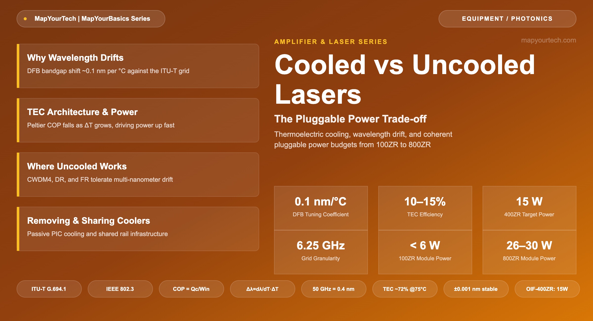
Cooled vs Uncooled Lasers: The Pluggable Power Trade-off
A thermoelectric cooler holds a DFB laser on its ITU grid line to within thousandths of a nanometer — and can draw more electrical power than the laser chip it is stabilizing.
1. Introduction
A cooled laser holds its emission wavelength with a thermoelectric cooler (TEC) that clamps the laser chip to a fixed set-point temperature and draws steady electrical power for as long as the module is powered. An uncooled laser removes the TEC entirely, letting the chip temperature track the case and the surrounding environment; it saves that steady power draw at the cost of a wavelength that moves with the operating temperature. Neither choice is universal — reach class, channel plan, and ambient operating range decide which one a given transceiver needs.
Pump and transmitter cooling is a real, measurable slice of a coherent module's power envelope, which is why removing or sharing a TEC has become a genuine lever for cutting the power a line card or pluggable draws. This article works through the physics of wavelength drift, the TEC's own power budget, where the industry accepts an uncooled laser today, and how design teams are removing or consolidating cooling hardware to save power at the module and line-system level.
2. Why Wavelength Drifts With Temperature
Semiconductor laser wavelength tracks the bandgap of the active region, and bandgap energy shrinks as the crystal lattice heats and expands. In a distributed feedback (DFB) laser, the grating period sets the lasing wavelength, and that period, together with the material's refractive index, shifts with chip temperature. For a typical 1550 nm telecom DFB, the thermal tuning coefficient runs about 0.08 to 0.12 nm/°C, with 0.1 nm/°C the commonly quoted working figure across laser-vendor datasheets and diode-laser thermal literature — a measured, well-repeated value rather than a theoretical one.
The industry's frequency grid is what makes that number consequential. ITU-T Recommendation G.694.1 anchors the DWDM grid at 193.1 THz and defines a flexible grid with 6.25 GHz central-frequency granularity, alongside legacy fixed spacings of 100, 50, 25, and 12.5 GHz — a standard-specified reference every DWDM vendor designs to. A 50 GHz channel is about 0.4 nm wide near 1550 nm; a 100 GHz channel is about 0.8 nm. The MapYourTech guide to the ITU-T G.694.1 DWDM channel grid works through the fixed- and flexible-grid math in full.
Δλ = (dλ/dT) × ΔT
Where: Δλ = wavelength shift (nm) · dλ/dT = thermal tuning coefficient, typically 0.08–0.12 nm/°C for a 1550 nm DFB · ΔT = temperature excursion at the laser chip (°C)
Practical Example — an uncooled chip riding a 40°C ambient swing (0°C to 40°C case temperature) with dλ/dT = 0.1 nm/°C drifts Δλ = 4 nm. Against a 50 GHz (0.4 nm) DWDM slot, that is enough drift to walk the laser across roughly ten adjacent channels; against a 20 nm CWDM4 slot, it is a tenth of the available window and stays put.
A TEC removes that dependency by holding the chip at a fixed set-point. Commercial cooled DFB modules routinely control chip temperature to about ±0.01°C, which keeps the resulting wavelength stable to roughly ±0.001 nm — several orders tighter than any DWDM grid requires, and the margin exists because grid stability also has to survive component aging and filter-passband narrowing over the module's service life. An uncooled laser has no such correction: its wavelength rides the case temperature directly, following the ~0.1 nm/°C coefficient across whatever range the enclosure sees.
Takeaway: Wavelength drift is a fixed physical property of the laser chip — roughly 0.1 nm/°C for a 1550 nm DFB — and whether that drift matters depends entirely on how wide the assigned channel slot is. The cooling decision is really a channel-plan decision.
3. Inside the Cooled Laser: TEC Architecture and Power Draw
A cooled DFB ships inside a hermetically sealed package — the 14-pin butterfly package is the long-standing industry form — containing five functional pieces: the laser chip, a submount that conducts heat away from the chip, the TEC beneath the submount, a thermistor that measures chip temperature, and an automatic temperature control (ATC) loop that drives TEC current to hold the thermistor reading constant. A companion automatic power control (APC) loop, fed by a back-facet monitor photodiode, holds optical output constant independently of the ATC loop.
The TEC itself is a Peltier device: driving current through it moves heat from one face to the other, pulling heat away from the laser chip and rejecting it into the case. Its coefficient of performance — the ratio of heat pumped to electrical power consumed — falls as the temperature difference between the hot and cold sides grows. That means TEC input power does not scale linearly with the heat load it removes; it climbs faster as ambient temperature rises and the case-to-chip ΔT widens. Practical TECs used in laser modules run at roughly 10 to 15% overall efficiency, a typical figure reported across thermoelectric packaging literature, so the electrical power a TEC draws is commonly several times the heat load it is moving.
COP = Qc / Win
Where: Qc = heat pumped away from the laser chip at the cold junction (W) · Win = electrical power supplied to the TEC (W). COP falls as the hot-side-to-cold-side ΔT grows, so Win must rise faster than linearly to hold the same Qc at higher ambient temperature.
Practical Example — 14xx-nm Raman Pump Laser Module
Namiki, Tsukiji, and Emori's characterization of a butterfly-packaged 14xx-nm pump laser module reports that at a 75°C case temperature, the laser diode draws about 2.8 W to deliver 400 mW of fiber-coupled output, while the TEC alone draws about 7.2 W to hold that case temperature — the TEC accounts for roughly 72% of the module's 10 W total electrical draw at that operating corner. At a 35°C case temperature the same laser needs a much smaller TEC contribution, because the ΔT the TEC has to sustain is far narrower. This measured curve is the same non-linear COP behavior the formula above describes, taken from a real production laser module rather than a textbook derivation.
The consequence for a system architect is that TEC power is not a fixed line item. It is a function of the ambient temperature the module has to survive, and it can dominate a laser module's power budget at the high end of a commercial or extended operating range. For how amplifier line cards budget power across pump lasers and their coolers at the span level, see the MapYourTech piece on Raman amplification fundamentals and the companion guide on the clean-fiber zone in Raman links.
4. Where Uncooled Lasers Work
Two conditions make an uncooled laser viable: enough wavelength separation between channels that a multi-nanometer drift cannot collide with a neighbor, and a link that does not route through a narrow-passband multiplexer. IEEE 802.3 together with the CWDM4 MSA defines the 100G CWDM4 client optic on four wavelengths from 1271 to 1331 nm with 20 nm spacing and a ±6.5 nm per-channel range — wide enough that a free-running DFB across its full commercial temperature range stays inside its assigned window without a TEC. Compare that to 100G LAN WDM, used in 100GBASE-LR4, which packs four channels into 800 GHz (about 4.5 nm) spacing; that grid is tight enough that LR4 optics require temperature control even though they carry the same 100 Gb/s payload as CWDM4.
The same logic sorts the standard reach-class ladder used across client and DCI optics, summarized in Table 1. Short-reach SR, DR, and FR optics typically run uncooled lasers, because SR uses multimode VCSELs outside any DWDM grid and DR/FR use the coarse O-band CWDM plan; LR, ER, and ZR optics move onto LAN WDM or full ITU-T DWDM grids and need a TEC to stay on-channel. The MapYourTech guide on QSFP-DD optical transceivers maps these reach classes onto the QSFP-DD and OSFP ecosystems in more detail, and the coherent vs. direct-detect selection guide covers the broader boundary between the two detection families.
| Reach Class | Typical Reach | Wavelength Plan | Laser Cooling |
|---|---|---|---|
| SR | 100–300 m | Multimode, 850 nm — no DWDM grid | Uncooled |
| DR | 500 m | O-band, coarse spacing | Uncooled |
| FR | 2 km | O-band, CWDM4: 1271–1331 nm, 20 nm spacing | Uncooled |
| LR | 10 km | LAN WDM, 800 GHz (~4.5 nm) spacing | Cooled |
| ER | 40 km | LAN WDM / DWDM | Cooled |
| ZR | 80 km and beyond | Full ITU-T G.694.1 DWDM grid | Cooled |
Reach classes and wavelength-plan conventions per IEEE 802.3 and the CWDM4 MSA (standard-specified); reach figures are typical values used across the transceiver industry.
Coherent line-side transmitters sit at the opposite extreme from an uncooled client optic. They use a tunable external-cavity laser — an ITLA, micro-ITLA, or nano-ITLA — that must hold a narrow linewidth for phase-sensitive detection while landing on any ITU-T grid line the operator assigns. That combination requires a TEC by definition, not by choice, which is why every coherent pluggable, from the smallest to the largest, carries a cooled laser inside it.
5. The Power Budget: TEC Share of Pluggable Modules
Coherent pluggables make the TEC's power cost visible at the module level, because the tunable laser, modulator, and DSP all share one power budget behind a single connector. The Optical Internetworking Forum set an original target of 15 W for the 400ZR module — a QSFP-DD or OSFP part delivering 400 Gb/s over up to 120 km with amplification — a standard-specified figure from the OIF-400ZR Implementation Agreement. Shipping 400ZR modules commonly land in the 16 to 22 W range once production DSP, laser, and modulator margins are accounted for, and the OpenZR+ MSA, which adds reach and OTN features on top of 400ZR, targets up to 20 W. The step to 800ZR pushes typical module power to about 26 to 30 W across current OSFP coherent deployments, which is part of why the industry moved 800G coherent from QSFP-DD toward OSFP: the larger body simply has more room for a heatsink.
Not every coherent class pays that price. Cisco's 100ZR QSFP28 module — built for access, aggregation, and metro interconnect rather than long-haul — draws under 5.5 W in its first generation and under 6 W in its second, a vendor-reported figure, because its lower baud rate and shorter reach target need far less DSP and laser power than a 400ZR or 800ZR part. That spread, from under 6 W to nearly 30 W across the coherent pluggable family, is mostly DSP and modulator scaling — but the tunable laser and its TEC are a fixed, non-negotiable slice of every one of these budgets, because coherent detection cannot work with a free-running laser. The 800G ZR/ZR+ coherent optics guide and the IP over DWDM (IPoDWDM) primer cover how these modules plug directly into routers.
| Module Class | Form Factor | Typical Power | Evidence |
|---|---|---|---|
| 100G ZR (Gen 1) | QSFP28 | < 5.5 W | Vendor claim (Cisco) |
| 100G ZR (Gen 2) | QSFP28 | < 6 W | Vendor claim (Cisco) |
| 400ZR | QSFP-DD / OSFP | 15 W target, 16–22 W shipping | Standard target (OIF) / market range |
| OpenZR+ | QSFP-DD / OSFP | ≤20 W target, 18–22 W shipping | Standard target (MSA) / market range |
| 800ZR | OSFP | 26–30 W | Market range |
For the rack- and facility-level consequences of these numbers — what a few extra watts per port costs in cooling and power provisioning — see the MapYourTech analysis of the power-per-bit case for router optics and the broader piece on power consumption trends in optical networks.
6. Removing and Sharing Coolers as a Design Lever
Three design responses follow from the fact that TEC power is real and non-linear with ambient temperature. The first is simple: do not cool what does not need it. Photonic integrated circuits that only need to stay within a coarse thermal window can sit on a thermally conductive substrate, such as aluminum nitride, and rely on the module housing as a heat sink instead of an active TEC — a passive approach reported in photonic-packaging engineering literature that trades some ambient operating range and design margin for the TEC's continuous power draw. This is the same logic that lets DR and FR client optics skip the TEC an LR or ZR part needs.
The second response is sharing cooling and amplification hardware across more than one channel or path instead of duplicating it per unit. Ciena's RLS Hyper-Rail line system illustrates the idea at the amplifier-hut level: instead of building dedicated amplification, monitoring, and control hardware for every fiber pair, the platform integrates that hardware into shared, ultra-dense modules serving multiple parallel "rails," and Ciena states the approach delivers up to 75% lower power and 32 times better rack density than single-rail deployments — a vendor claim tied to its 2026 hyperscale AI-interconnect positioning. The same consolidation instinct shows up across Ciena's own coherent DSP roadmap: the company reports more than an 85% cumulative reduction in watts per gigabit for its WaveLogic coherent optics line since 2008, largely by folding functions that once needed separate power-hungry stages into fewer, more integrated ones — again a vendor-reported figure, not an independently audited one.
Trade-off: sharing hardware also shares its failure domain, which is the cost a per-unit dedicated design does not carry. A TEC or pump module serving one laser only affects that laser if it fails; a shared subsystem serving several rails or channels degrades all of them at once. Any design that consolidates cooling or amplification hardware to save power has to budget for that correlated-failure risk explicitly, through redundancy or faster fault isolation, rather than treating the power saving as free.
7. Practical Guidelines
- Specify a cooled laser when the link routes through a mux, demux, or ROADM filter with sub-nanometer passband tolerance, or when the ambient operating range extends into extended-temperature outdoor enclosures where an uncooled chip would drift across several channel slots.
- Specify uncooled when the wavelength plan already tolerates several nanometers of movement — CWDM4, DR, and FR client optics — and the deployment sits inside a temperature-controlled data center hall.
- Treat TEC and pump-laser cooling power as a design variable, not a constant. A module rated for full extended-temperature operation carries a materially larger cooling power budget than the same design rated for a controlled indoor environment, because of the non-linear COP relationship in Section 3.
- Where one chassis serves multiple channels, rails, or wavelengths, weigh whether shared cooling and amplification infrastructure is worth its correlated-failure exposure before committing to it — the power and density gains are real, but so is the reduced fault isolation.
8. Summary
A cooled laser trades steady TEC power for wavelength precision; an uncooled laser trades that precision for a lower, temperature-dependent power draw. The physics is simple — a DFB's ~0.1 nm/°C drift is trivial against a 20 nm CWDM4 channel and serious against a 0.4 nm 50 GHz DWDM slot — but the TEC's non-linear power curve against ambient temperature is what turns cooling from a footnote into a real slice of a module's or line card's power budget. Coherent pluggables make that budget visible: sub-6 W 100ZR parts sit beside 26–30 W 800ZR modules, with a tunable, always-cooled laser as the one line item every class shares. Removing coolers where the application tolerates it, and sharing them where it does not, are both legitimate design levers, as long as the shared-failure trade-off is priced in alongside the power saving.
References
- ITU-T Recommendation G.694.1 — Spectral grids for WDM applications: DWDM frequency grid, ITU-T Study Group 15.
- Optical Internetworking Forum (OIF), Implementation Agreement OIF-400ZR — 400ZR.
- IEEE 802.3 — Ethernet, IEEE Standards Association.
- S. Namiki, N. Tsukiji, and Y. Emori, "Pump Laser Diodes and WDM Pumping," in Raman Amplifiers for Telecommunications, M. N. Islam (Ed.), Springer.
Sanjay Yadav, "Optical Network Communications: An Engineer's Perspective" – Bridge the Gap Between Theory and Practice in Optical Networking.
Related Articles on MapYourTech






