
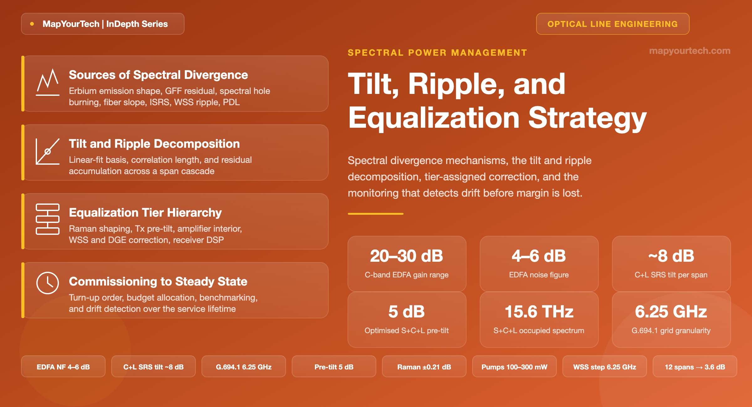
Spectral Power Management at Scale: Tilt, Ripple, and Equalization Strategy
A network-level strategy for spectral flatness across amplified DWDM lines: the equalization tier hierarchy, ripple accumulation across a cascade, and the monitoring decomposition that detects divergence before margin is lost.
1. Introduction
A commissioned C-band line leaves the factory flat and does not stay that way. The gain flattening filter inside each erbium-doped fiber amplifier (EDFA) was designed to cancel the erbium gain shape at one specific inversion level, and the moment the amplifier runs at a gain other than its nominal setpoint, a residual shape reappears. That residual is small — a few tenths of a decibel across the band. Cascade twelve amplifiers whose filters share the same design and whose spans share the same loss slope, and the residual is no longer small. It is the difference between a line that carries 400G everywhere and a line that carries 400G in the middle of the band and 200G at the edges.
Spectral power management is the discipline that keeps that from happening. It is not amplifier tuning, and it is not a commissioning task that finishes. It is a network-level control problem with three distinct questions: which physical mechanisms move channel power away from target, which actuator in the node hierarchy has the right spectral resolution to pull it back, and which measurement indicates divergence while margin remains available.
The three questions have different answers than they did a decade ago, for a specific reason. Coherent transponders with soft-decision forward error correction (FEC) and probabilistic constellation shaping made per-channel capacity a continuous function of generalized signal-to-noise ratio (GSNR) rather than a pass/fail threshold. A channel that runs 3 dB low no longer fails — it downshifts to a lower rate, and the network delivers less capacity than designed while every alarm remains clear. Spectral flatness stopped being a compliance item and became a capacity item.
1.1 Article Scope and Structure
The physical origins of divergence come first: erbium gain shape and its dependence on inversion, gain flattening filter residual, spectral hole burning, the wavelength dependence of fiber attenuation, wavelength selective switch (WSS) port ripple, and the one mechanism that dominates everything once bandwidth grows past the C-band — inter-channel stimulated Raman scattering (ISRS).
Then the decomposition that makes the problem tractable. A spectral sweep across 96 channels is 96 numbers, and 96 numbers per amplifier per direction across a hundred-node network is not a manageable quantity. Fit the sweep to a mean, a linear slope, and a residual, and it becomes three numbers that map one-to-one onto three classes of actuator. The mean maps to amplifier gain. The slope maps to the tilt control element. The residual maps to per-slot attenuation in a WSS or dynamic gain equalizer (DGE). The decomposition is not a mathematical convenience; it is the reason the node hierarchy is built the way it is.
Then accumulation, which is where most of the engineering judgment lives. Contributions that are correlated across a cascade — every amplifier of the same model carrying the same filter residual, every span of the same fiber type carrying the same loss slope — add linearly with span count. Contributions that are uncorrelated add as the square root. A design that treats all ripple as random will underestimate the far-end spread by a factor that grows with the square root of the cascade length, and a twelve-span line is where that factor stops being academic.
Then where equalization belongs. There are four candidate locations — transmitter, amplifier interior, node WSS, and the digital domain at the receiver — and only two of them can actually move power. The strategy question is not which one to use but how to divide the work so that each actuator corrects what it is physically capable of correcting and nothing else, because a WSS asked to fix a problem an amplifier tilt element should have corrected incurs the cost in optical signal-to-noise ratio (OSNR).
And finally the monitoring that closes the loop: which quantities to trend, what a step change means versus a slow drift, how to separate a real optical event from an optical channel monitor calibration shift, and why equalizer attenuation consumption is the single most useful health metric on an amplified line.
1.2 Audience and Reading Guidance
Anyone commissioning, planning, or operating an amplified DWDM line will find the actuator map and the monitoring decomposition directly usable. Anyone designing one will care more about the accumulation mathematics and the argument for equalization interval. Anyone early in an engineering career can read Sections 2 and 4 as a self-contained explanation of why an amplifier that looks flat on a bench does not stay flat in a network, and skip the model derivations on a first pass.
Takeaway: Spectral flatness is a capacity problem, not a compliance problem. Coherent transponders convert power deviation into reduced spectral efficiency rather than into alarms, so a line can lose a quarter of its designed throughput without a single indication that anything is wrong. The measurement discipline has to find the loss, because the transponder will not report it.
2. Sources of Spectral Divergence
Nine mechanisms move channel power away from its target across an amplified line. They differ in magnitude, in spectral shape, in whether they are static or load-dependent, and — most importantly for cascade behaviour — in whether they repeat identically at every site or vary randomly. That last property decides everything about how they accumulate.
2.1 Erbium Gain Shape and Inversion Dependence
The erbium ion in a silica host has an emission cross-section that peaks sharply near 1532 nm, dips near 1540 nm, and forms a broad, comparatively flat shoulder from roughly 1545 nm to 1562 nm. Left uncorrected, a single EDFA stage delivers several decibels more gain at the 1532 nm peak than on the shoulder. This is the raw gain spectrum, and it is a property of the erbium-doped fiber, not of the amplifier design.
The part that matters operationally is that the shape is a function of average inversion, not a fixed curve. Raise the pump power and the population inversion rises; the gain grows everywhere, but it grows faster at the short-wavelength peak than on the long-wavelength shoulder. Lower the inversion and the reverse happens — the short end falls faster. The consequence is a nearly linear-in-decibels rotation of the gain spectrum as gain changes, which the industry calls dynamic gain tilt (DGT). It is deterministic, repeatable, and characterized per amplifier model, which is exactly why it is correctable with a single control input.
Gain range in a typical C-band EDFA runs roughly 20 dB to 30 dB depending on pump power and erbium-doped fiber length, with a noise figure in the 4 dB to 6 dB range (typical values from amplifier design practice). The design point at commissioning is to set gain equal to measured span loss. When the span loss is not what the design assumed — a repaired cable, an added connector pair, an aged splice — the amplifier runs off its nominal gain, and DGT delivers a tilt that was never commanded.
2.2 Gain Flattening Filter Residual
A gain flattening filter (GFF) is a passive wavelength-dependent loss element, built as a thin-film filter or a long-period fiber grating, whose transmission spectrum is the inverse of the erbium gain shape at one chosen inversion. Placed in the mid-stage of a two-stage amplifier, it cancels the gain shape and delivers a flat output. The design and cascade behaviour of gain flattening filters is a separate topic, but two properties matter here.
First, the cancellation is exact at one inversion only. Run the amplifier at a different gain and the GFF still applies its designed loss curve while the erbium gain curve has rotated — the mismatch appears as residual tilt plus residual shape. Second, the filter itself has a manufacturing error function. No filter matches its target curve exactly, and the residual is specified in tenths of a decibel across the band (vendor specification class, varying by filter technology and by supplier).
Both residuals are small per amplifier. Both are the same at every amplifier of the same model, which is the property that makes them dangerous. Fiber Bragg grating GFFs are sometimes offered specifically on the argument that each filter shape is individually fitted, so cascading several of them does not accumulate a common error — an argument that only makes sense because the alternative does accumulate.
2.3 Spectral Hole Burning
Erbium in silica is predominantly homogeneously broadened at room temperature, which is why a change in one channel's power changes gain for all channels. It is not perfectly homogeneous. A strongly saturating channel depletes the sub-population of ions whose local site environment resonates near its wavelength, producing a localized dip in gain centred on that channel — spectral hole burning (SHB). At room temperature in silica the hole is broad, spanning several nanometres, and shallow.
SHB is worth naming because it explains an otherwise puzzling observation: a spectrum that was flat at full fill develops shallow depressions where the strongest channel groups sit, and the depressions move when the channel plan changes. It is load-dependent, it is not corrected by a fixed GFF, and it is the mechanism that makes uniform channel loading an engineering requirement rather than a cosmetic preference. Where it fails as an explanation: SHB depth in commercial C-band amplifiers at practical inversion is a fraction of a decibel, so if a sweep shows a 2 dB localized dip, check for a filter or a WSS port before attributing the dip to the fiber.
2.4 Wavelength Dependence of Fiber Attenuation
ITU-T G.652.D fiber has an attenuation minimum near 1550 nm to 1570 nm and rises on both sides. Across the C-band alone the variation is small, on the order of hundredths of a decibel per kilometre; across C+L it is larger, and across a full multiband allocation reaching into S and E it becomes one of the dominant shapes. Multiply by span length and it stops being a rounding error: a variation of 0.02 dB/km across the occupied band over a 90 km span is roughly 1.8 dB of slope arriving at the next amplifier input (approximate; the exact value depends on fiber vintage, cable design, and the band edges chosen).
This shape is static, it does not depend on traffic, and it repeats at every span of the same fiber type. Correlated accumulation again.
2.5 Inter-Channel Stimulated Raman Scattering
This is the mechanism that reorganized the whole discipline. Silica has a Raman gain spectrum extending roughly 13 THz from the pump, which means that in a wideband WDM comb the short-wavelength channels act as pumps for the long-wavelength channels. Power flows from blue to red, continuously, along the entire span. Short-wavelength channels lose power and OSNR; long-wavelength channels gain power and move closer to their nonlinear threshold.
Read the Full Analysis with Premium
The remaining 89% of this article — the design numbers, trade-offs and field guidance — is part of MapYourTech Premium, along with the full premium library, courses and professional tools.
You May Also Like
-
Free
-
August 31, 2026
-
Free
-
August 27, 2026