Animated CTA Banner
MapYourTech
MapYourTech has always been about YOUR tech journey, YOUR questions, YOUR thoughts, and most importantly, YOUR growth. It’s a space where we "Map YOUR Tech" experiences and empower YOUR ambitions.
To further enhance YOUR experience, we are working on delivering a professional, fully customized platform tailored to YOUR needs and expectations.
Thank you for the love and support over the years. It has always motivated us to write more, share practical industry insights, and bring content that empowers and inspires YOU to excel in YOUR career.
We truly believe in our tagline:
“Share, explore, and inspire with the tech inside YOU!”
Let us know what YOU would like to see next! Share YOUR thoughts and help us deliver content that matters most to YOU.
Share YOUR Feedback
Tag

optical

Browsing

NETCONF (Network Configuration Protocol) is a modern protocol developed to address the limitations of older network management protocols like SNMP, especially for configuration management. It provides a robust, scalable, and secure method for managing network devices, supporting both configuration and operational data retrieval. NETCONF is widely used in modern networking environments, where automation, programmability, and fine-grained control are essential. Lets explore the NETCONF protocol, its architecture, advantages, use cases, security, and when to use it.

What Is NETCONF?

NETCONF (defined in RFC 6241) is a network management protocol that allows network administrators to install, manipulate, and delete the configuration of network devices. Unlike SNMP, which is predominantly used for monitoring, NETCONF focuses on configuration management and supports advanced features like transactional changes and candidate configuration models.

Key Features:

  • Transaction-based Configuration: NETCONF allows administrators to make changes to network device configurations in a transactional manner, ensuring either full success or rollback in case of failure.
  • Data Model Driven: NETCONF uses YANG (Yet Another Next Generation) as a data modeling language to define configuration and state data for network devices.
  • Extensible and Secure: NETCONF is transport-independent and typically uses SSH (over port 830) to provide secure communication.
  • Structured Data: NETCONF exchanges data in a structured XML format, ensuring clear, programmable access to network configurations and state information.

How NETCONF Works

NETCONF operates in a client-server architecture where the NETCONF client (usually a network management tool or controller) interacts with the NETCONF server (a network device) over a secure transport layer (commonly SSH). NETCONF performs operations like configuration retrieval, validation, modification, and state monitoring using a well-defined set of Remote Procedure Calls (RPCs).

NETCONF Workflow:

  1. Establish Session: The NETCONF client establishes a secure session with the device (NETCONF server), usually over SSH.
  2. Retrieve/Change Configuration: The client sends a <get-config> or <edit-config> RPC to retrieve or modify the device’s configuration.
  3. Transaction and Validation: NETCONF allows the use of a candidate configuration, where changes are made to a candidate datastore before committing to the running configuration, ensuring the changes are validated before they take effect.
  4. Apply Changes: Once validated, changes can be committed to the running configuration. If errors occur during the process, the transaction can be rolled back to a stable state.
  5. Close Session: After configuration changes are made or operational data is retrieved, the session can be closed securely.

NETCONF Operations

NETCONF supports a range of operations, defined as RPCs (Remote Procedure Calls), including:

  • <get>: Retrieve device state information.
  • <get-config>: Retrieve configuration data from a specific datastore (e.g., running, startup).
  • <edit-config>: Modify the configuration data of a device.
  • <copy-config>: Copy configuration data from one datastore to another.
  • <delete-config>: Remove configuration data from a datastore.
  • <commit>: Apply changes made in the candidate configuration to the running configuration.
  • <lock> / <unlock>: Lock or unlock a configuration datastore to prevent conflicting changes.

These RPC operations allow network administrators to efficiently retrieve, modify, validate, and deploy configuration changes.

NETCONF Datastores

NETCONF supports different datastores for storing device configurations. The most common datastores are:

  • Running Configuration: The current active configuration of the device.
  • Startup Configuration: The configuration that is loaded when the device boots.
  • Candidate Configuration: A working configuration area where changes can be tested before committing them to the running configuration.

The candidate configuration model provides a critical advantage over SNMP by enabling validation and rollback mechanisms before applying changes to the running state.

NETCONF and YANG

One of the key advantages of NETCONF is its tight integration with YANG, a data modeling language that defines the data structures used by network devices. YANG models provide a standardized way to represent device configurations and state information, ensuring interoperability between different devices and vendors.

YANG is essential for defining the structure of data that NETCONF manages, and it supports hierarchical data models that allow for more sophisticated and programmable interactions with network devices.

Security in NETCONF

NETCONF is typically transported over SSH (port 830), providing strong encryption and authentication for secure network device management. This is a significant improvement over SNMPv1 and SNMPv2c, which lack encryption and rely on clear-text community strings.

In addition to SSH, NETCONF can also be used with TLS (Transport Layer Security) or other secure transport layers, making it adaptable to high-security environments.

Advantages of NETCONF

NETCONF offers several advantages over legacy protocols like SNMP, particularly in the context of configuration management and network automation:

  • Transaction-Based Configuration: NETCONF ensures that changes are applied in a transactional manner, reducing the risk of partial or incorrect configuration updates.
  • YANG Model Integration: The use of YANG data models ensures structured, vendor-neutral device configuration, making automation easier and more reliable.
  • Security: NETCONF uses secure transport protocols (SSH, TLS), protecting network management traffic from unauthorized access.
  • Efficient Management: With support for retrieving and manipulating large configuration datasets in a structured format, NETCONF is highly efficient for managing modern, large-scale networks.
  • Programmability: The structured XML or JSON data format and support for standardized YANG models make NETCONF highly programmable, ideal for software-defined networking (SDN) and network automation.

Disadvantages of NETCONF

Despite its many advantages, NETCONF does have some limitations:

  • Complexity: NETCONF is more complex than SNMP, requiring an understanding of XML data structures and YANG models.
  • Heavy Resource Usage: XML data exchanges are more verbose than SNMP’s simple GET/SET operations, potentially using more network and processing resources.
  • Limited in Legacy Devices: Not all legacy devices support NETCONF, meaning a mix of protocols may need to be managed in hybrid environments.

When to Use NETCONF

NETCONF is best suited for large, modern networks where programmability, automation, and transactional configuration changes are required. Key use cases include:

  • Network Automation: NETCONF is a foundational protocol for automating network configuration changes in software-defined networking (SDN) environments.
  • Data Center Networks: Highly scalable and automated networks benefit from NETCONF’s structured configuration management.
  • Cloud and Service Provider Networks: NETCONF is well-suited for multi-vendor environments where standardization and automation are necessary.

NETCONF vs. SNMP: A Quick Comparison

NETCONF Implementation Steps

Here is a general step-by-step process to implement NETCONF in a network:

Step 1: Enable NETCONF on Devices

Ensure that your network devices (routers, switches) support NETCONF and have it enabled. For example, on Cisco devices, this can be done with:

netconf ssh

Step 2: Install a NETCONF Client

To interact with devices, install a NETCONF client (e.g., ncclient in Python or Ansible modules that support NETCONF).

Step 3: Define the YANG Models

Identify the YANG models that are relevant to your device configurations. These models define the data structures NETCONF will manipulate.

Step 4: Retrieve or Edit Configuration

Use the <get-config> or <edit-config> RPCs to retrieve or modify device configurations. An example RPC call using Python’s ncclient might look like this:

from ncclient import manager

with manager.connect(host="192.168.1.1", port=830, username="admin", password="admin", hostkey_verify=False) as m: 
    config = m.get_config(source='running') 
    print(config)

Step 5: Validate and Commit Changes

Before applying changes, validate the configuration using <validate>, then commit it using <commit>.

Summary

NETCONF is a powerful, secure, and highly structured protocol for managing and automating network device configurations. Its tight integration with YANG data models and support for transactional configuration changes make it an essential tool for modern networks, particularly in environments where programmability and automation are critical. While more complex than SNMP, NETCONF provides the advanced capabilities necessary to manage large, scalable, and secure networks effectively.

Reference

https://www.cisco.com/c/en/us/td/docs/ios-xml/ios/prog/configuration/1611/b_1611_programmability_cg/configuring_yang_datamodel.pdf

Stimulated Brillouin Scattering (SBS) is an inelastic scattering phenomenon that results in the backward scattering of light when it interacts with acoustic phonons (sound waves) in the optical fiber. SBS occurs when the intensity of the optical signal reaches a certain threshold, resulting in a nonlinear interaction between the optical field and acoustic waves within the fiber. This effect typically manifests at lower power levels compared to other nonlinear effects, making it a significant limiting factor in optical communication systems, particularly those involving long-haul transmission and high-power signals.

Mechanism of SBS

SBS is caused by the interaction of an incoming photon with acoustic phonons in the fiber material. When the intensity of the light increases beyond a certain threshold, the optical signal generates an acoustic wave in the fiber. This acoustic wave, in turn, causes a periodic variation in the refractive index of the fiber, which scatters the incoming light in the backward direction. This backscattered light is redshifted in frequency due to the Doppler effect, with the frequency shift typically around 10 GHz (depending on the fiber material and the wavelength of light).

The Brillouin gain spectrum is relatively narrow, with a typical bandwidth of around 20 to 30 MHz. The Brillouin threshold power Pth can be calculated as:

Pth=21AeffgBLeff

Where:

  • Aeff is the effective area of the fiber core,
  • gB is the Brillouin gain coefficient,
  • Leff is the effective interaction length of the fiber.

When the power of the incoming light exceeds this threshold, SBS causes a significant amount of power to be reflected back towards the source, degrading the forward-propagating signal and introducing power fluctuations in the system.

Image credit: corning.com

Impact of SBS in Optical Systems

SBS becomes problematic in systems where high optical powers are used, particularly in long-distance transmission systems and those employing Wavelength Division Multiplexing (WDM). The main effects of SBS include:

  1. Power Reflection:
    • A portion of the optical power is scattered back towards the source, which reduces the forward-propagating signal power. This backscattered light interferes with the transmitter and receiver, potentially causing signal degradation.
  2. Signal Degradation:
    • SBS can cause signal distortion, as the backward-propagating light interferes with the incoming signal, leading to fluctuations in the transmitted power and an increase in the bit error rate (BER).
  3. Noise Increase:
    • The backscattered light adds noise to the system, particularly in coherent systems, where phase information is critical. The interaction between the forward and backward waves can distort the phase and amplitude of the transmitted signal, worsening the signal-to-noise ratio (SNR).

SBS in Submarine Systems

In submarine communication systems, SBS poses a significant challenge, as these systems typically involve long spans of fiber and require high power levels to maintain signal quality over thousands of kilometers. The cumulative effect of SBS over long distances can lead to substantial signal degradation. As a result, submarine systems must employ techniques to suppress SBS and manage the power levels appropriately.

Mitigation Techniques for SBS

Several methods are used to mitigate the effects of SBS in optical communication systems:

  1. Reducing Signal Power:
    • One of the simplest ways to reduce the onset of SBS is to lower the optical signal power below the Brillouin threshold. However, this must be balanced with maintaining sufficient power for the signal to reach its destination with an acceptable signal-to-noise ratio (SNR).
  2. Laser Linewidth Broadening:
    • SBS is more efficient when the signal has a narrow linewidth. By broadening the linewidth of the signal, the power is spread over a larger frequency range, reducing the power density at any specific frequency and lowering the likelihood of SBS. This can be achieved by modulating the laser source with a low-frequency signal.
  3. Using Shorter Fiber Spans:
    • Reducing the length of each fiber span in the transmission system can decrease the effective length over which SBS can occur. By using optical amplifiers to boost the signal power at regular intervals, it is possible to maintain signal strength without exceeding the SBS threshold.
  4. Raman Amplification:
    • SBS can be suppressed using distributed Raman amplification, where the signal is amplified along the length of the fiber rather than at discrete points. By keeping the power levels low in any given section of the fiber, Raman amplification reduces the risk of SBS.

Applications of SBS

While SBS is generally considered a detrimental effect in optical communication systems, it can be harnessed for certain useful applications:

  1. Brillouin-Based Sensors:
    • SBS is used in distributed fiber optic sensors, such as Brillouin Optical Time Domain Reflectometry (BOTDR) and Brillouin Optical Time Domain Analysis (BOTDA). These sensors measure the backscattered Brillouin light to monitor changes in strain or temperature along the length of the fiber. This is particularly useful in structural health monitoring and pipeline surveillance.
  2. Slow Light Applications:
    • SBS can also be exploited to create slow light systems, where the propagation speed of light is reduced in a controlled manner. This is achieved by using the narrow bandwidth of the Brillouin gain spectrum to induce a delay in the transmission of the optical signal. Slow light systems have potential applications in optical buffering and signal processing.

Summary

Stimulated Brillouin Scattering (SBS) is a nonlinear scattering effect that occurs at relatively low power levels, making it a significant limiting factor in high-power, long-distance optical communication systems. SBS leads to the backscattering of light, which degrades the forward-propagating signal and increases noise. While SBS is generally considered a negative effect, it can be mitigated using techniques such as power reduction, linewidth broadening, and Raman amplification. Additionally, SBS can be harnessed for beneficial applications, including optical sensing and slow light systems. Effective management of SBS is crucial for maintaining the performance and reliability of modern optical communication networks, particularly in submarine systems.

  • Stimulated Brillouin Scattering (SBS) is a nonlinear optical effect caused by the interaction between light and acoustic waves in the fiber.
  • It occurs when an intense light wave traveling through the fiber generates sound waves, which scatter the light in the reverse direction.
  • SBS leads to a backward-propagating signal, called the Stokes wave, that has a slightly lower frequency than the incoming light.
  • The effect typically occurs in single-mode fibers at relatively low power thresholds compared to other nonlinear effects like SRS.
  • SBS can result in power loss of the forward-propagating signal as some of the energy is reflected back as the Stokes wave.
  • The efficiency of SBS depends on several factors, including the fiber length, the optical power, and the linewidth of the laser source.
  • In WDM systems, SBS can degrade performance by introducing signal reflections and crosstalk, especially in long-haul optical links.
  • SBS tends to become more pronounced in narrow-linewidth lasers and fibers with low attenuation, making it a limiting factor for high-power transmission.
  • Mitigation techniques for SBS include using broader linewidth lasers, reducing the optical power below the SBS threshold, or employing SBS suppression techniques such as phase modulation.
  • Despite its negative impacts in communication systems, SBS can be exploited for applications like distributed fiber sensing and slow-light generation due to its sensitivity to acoustic waves.

Reference

Four-Wave Mixing (FWM) is a nonlinear optical phenomenon that occurs when multiple wavelengths of light are transmitted through a fiber simultaneously. FWM is a third-order nonlinear effect, and it results in the generation of new wavelengths (or frequencies) through the interaction of the original light waves. It is one of the most important nonlinear effects in Wavelength Division Multiplexing (WDM) systems, where multiple wavelength channels are used to increase the system capacity.

Physics behind FWM

FWM occurs when three optical waves, at frequencies 𝑓1,𝑓2 and 𝑓3, interact in the fiber to produce a fourth wave at a frequency 𝑓4, which is generated by the nonlinear interaction between the original waves. The frequency of the new wave is given by:

f4=f1+f2f3

This process is often referred to as third-order intermodulation, where new frequencies are created due to the mixing of the input signals. For FWM to be efficient, the interacting waves must satisfy certain phase-matching conditions, which depend on the chromatic dispersion and the effective refractive index of the fiber.

Mathematical Expression

The general formula for FWM efficiency can be expressed as:

PFWM=ηP1P2P3

Where:

  • 𝑃FWM is the power of the generated FWM signal.
  • 𝑃1,𝑃2,𝑃3 are the powers of the interacting signals.
  • 𝜂 is the FWM efficiency factor which depends on the fiber’s chromatic dispersion, the effective area, and the nonlinear refractive index.

The efficiency of FWM is highly dependent on the phase-matching condition, which is affected by the chromatic dispersion of the fiber. If the fiber has zero or low dispersion, FWM becomes more efficient, and more power is transferred to the new wavelengths. Conversely, in fibers with higher dispersion, FWM is less efficient.

Impact of FWM in WDM Systems

FWM has a significant impact in WDM systems, particularly when the channel spacing between the wavelengths is narrow. The main effects of FWM include:

  1. Crosstalk:
            • FWM generates new frequencies that can interfere with the original WDM channels, leading to crosstalk between channels. This crosstalk can degrade the signal quality, especially when the system operates with high power and closely spaced channels.
  2. Spectral Efficiency:
            • FWM can limit the spectral efficiency of the system by introducing unwanted signals in the spectrum. This imposes a practical limit on how closely spaced the WDM channels can be, as reducing the channel spacing increases the likelihood of FWM.
  3. Performance Degradation:
            • The new frequencies generated by FWM can overlap with the original signal channels, leading to increased bit error rates (BER) and reduced signal-to-noise ratios (SNR). This is particularly problematic in long-haul optical systems, where FWM accumulates over long distances.

FWM and Chromatic Dispersion

Chromatic dispersion plays a critical role in the occurrence of FWM. Dispersion-managed fibers can be designed to control the effects of FWM by increasing the phase mismatch between the interacting waves, thereby reducing FWM efficiency. In contrast, fibers with zero-dispersion wavelengths can significantly enhance FWM, as the phase-matching condition is more easily satisfied.

In practical systems, fibers with non-zero dispersion-shifted fibers (NZDSF) are often used to reduce the impact of FWM. NZDSF fibers have a dispersion profile that is designed to keep the system out of the zero-dispersion regime while minimizing the dispersion penalty.

Mitigation Techniques for FWM

Several techniques can be employed to mitigate the effects of FWM in optical communication systems:

  1. Increase Channel Spacing:By increasing the channel spacing between WDM signals, the interaction between channels is reduced, thereby minimizing FWM. However, this reduces the overall capacity of the system.
  2. Optimize Power Levels:Reducing the launch power of the optical signals can lower the nonlinear interaction and reduce the efficiency of FWM. However, this must be balanced with maintaining sufficient optical power to achieve the desired signal-to-noise ratio (SNR).
  3. Use Dispersion-Managed Fibers: As mentioned above, fibers with optimized dispersion profiles can be used to reduce the efficiency of FWM by increasing the phase mismatch between interacting wavelengths.
  4. Employ Advanced Modulation Formats:Modulation formats that are less sensitive to phase distortions, such as differential phase-shift keying (DPSK), can help reduce the impact of FWM on signal quality.
  5. Optical Phase Conjugation:Optical phase conjugation can be used to counteract the effects of FWM by reversing the nonlinear phase distortions. This technique is typically implemented in mid-span spectral inversion systems, where the phase of the signal is conjugated at a point in the transmission link.

Applications of FWM

Despite its negative impact on WDM systems, FWM can also be exploited for useful applications:

  1. Wavelength Conversion:
    • FWM can be used for all-optical wavelength conversion, where the interacting wavelengths generate a new wavelength that can be used for wavelength routing or switching in WDM networks.
  2. Signal Regeneration:
    • FWM has been used in all-optical regenerators, where the nonlinear interaction between signals is used to regenerate the optical signal, improving its quality and extending the transmission distance.

FWM in Submarine Systems

In submarine optical communication systems, where long-distance transmission is required, FWM poses a significant challenge. The accumulation of FWM over long distances can lead to severe crosstalk and signal degradation. Submarine systems often use large effective area fibers to reduce the nonlinear interactions and minimize FWM. Additionally, dispersion management is employed to limit the efficiency of FWM by introducing phase mismatch between the interacting waves.

Summary

Four-Wave Mixing (FWM) is a critical nonlinear effect in optical fiber communication, particularly in WDM systems. It leads to the generation of new wavelengths, causing crosstalk and performance degradation. Managing FWM is essential for optimizing the capacity and reach of optical systems, particularly in long-haul and submarine communication networks. Techniques such as dispersion management, power optimization, and advanced modulation formats can help mitigate the effects of FWM and improve the overall system performance.

  • Four-Wave Mixing (FWM) is a nonlinear optical effect that occurs when multiple wavelengths of light travel through a fiber, generating new frequencies from the original signals.
  • It’s a third-order nonlinear phenomenon and is significant in Wavelength Division Multiplexing (WDM) systems, where it can affect system capacity.
  • FWM happens when three optical waves interact to create a fourth wave, and its efficiency depends on the phase-matching condition, which is influenced by chromatic dispersion.
  • The formula for FWM efficiency depends on the power of the interacting signals and the FWM efficiency factor, which is impacted by the fiber’s dispersion and other parameters.
  • FWM can cause crosstalk in WDM systems by generating new frequencies that interfere with the original channels, degrading signal quality.
  • It reduces spectral efficiency by limiting how closely WDM channels can be spaced due to the risk of FWM.
  • FWM can lead to performance degradation in optical systems, especially over long distances, increasing error rates and lowering the signal-to-noise ratio (SNR).
  • Managing chromatic dispersion in fibers can reduce FWM’s efficiency, with non-zero dispersion-shifted fibers often used to mitigate the effect.
  • Techniques to reduce FWM include increasing channel spacing, optimizing power levels, using dispersion-managed fibers, and employing advanced modulation formats.
  • Despite its negative impacts, FWM can be useful for wavelength conversion and signal regeneration in certain optical applications, and it is a challenge in long-distance submarine systems.

Reference

  • https://link.springer.com/book/10.1007/978-3-030-66541-8

Exploring the C+L Bands in DWDM Network

DWDM networks have traditionally operated within the C-band spectrum due to its lower dispersion and the availability of efficient Erbium-Doped Fiber Amplifiers (EDFAs). Initially, the C-band supported a spectrum of 3.2 terahertz (THz), which has been expanded to 4.8 THz to accommodate increased data traffic. While the Japanese market favored the L-band early on, this preference is now expanding globally as the L-band’s ability to double the spectrum capacity becomes crucial. The integration of the L-band adds another 4.8 THz, resulting in a total of 9.6 THz when combined with the C-band.


What Does C+L Mean?

C+L band refers to two specific ranges of wavelengths used in optical fiber communications: the C-band and the L-band. The C-band ranges from approximately 1530 nm to 1565 nm, while the L-band covers from about 1565 nm to 1625 nm. These bands are crucial for transmitting signals over optical fiber, offering distinct characteristics in terms of attenuation, dispersion, and capacity.

c+l

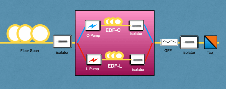
C+L Architecture

The Advantages of C+L

The adoption of C+L bands in fiber optic networks comes with several advantages, crucial for meeting the growing demands for data transmission and communication services:

  1. Increased Capacity: One of the most significant advantages of utilizing both C and L bands is the dramatic increase in network capacity. By essentially doubling the available spectrum for data transmission, service providers can accommodate more data traffic, which is essential in an era where data consumption is soaring due to streaming services, IoT devices, and cloud computing.
  2. Improved Efficiency: The use of C+L bands makes optical networks more efficient. By leveraging wider bandwidths, operators can optimize their existing infrastructure, reducing the need for additional physical fibers. This efficiency not only cuts costs but also accelerates the deployment of new services.
  3. Enhanced Flexibility: With more spectrum comes greater flexibility in managing and allocating resources. Network operators can dynamically adjust bandwidth allocations to meet changing demand patterns, improving overall service quality and user experience.
  4. Reduced Attenuation and Dispersion: Each band has its own set of optical properties. By carefully managing signals across both C and L bands, it’s possible to mitigate issues like signal attenuation and chromatic dispersion, leading to longer transmission distances without the need for signal regeneration.

Challenges in C+L Band Implementation:

  1. Stimulated Raman Scattering (SRS): A significant challenge in C+L band usage is SRS, which causes a tilt in power distribution from the C-band to the L-band. This effect can create operational issues, such as longer recovery times from network failures, slow and complex provisioning due to the need to manage the power tilt between the bands, and restrictions on network topologies.
  2. Cost: The financial aspect is another hurdle. Doubling the components, such as amplifiers and wavelength-selective switches (WSS), can be costly. Network upgrades from C-band to C+L can often mean a complete overhaul of the existing line system, a deterrent for many operators if the L-band isn’t immediately needed.
  3. C+L Recovery Speed: Network recovery from failures can be sluggish, with times hovering around the 60ms to few seconds mark.
  4. C+L Provisioning Speed and Complexity: The provisioning process becomes more complicated, demanding careful management of the number of channels across bands.

The Future of C+L

The future of C+L in optical communications is bright, with several trends and developments on the horizon:

  • Integration with Emerging Technologies: As 5G and beyond continue to roll out, the integration of C+L band capabilities with these new technologies will be crucial. The increased bandwidth and efficiency will support the ultra-high-speed, low-latency requirements of future mobile networks and applications.
  • Innovations in Fiber Optic Technology: Ongoing research in fiber optics, including new types of fibers and advanced modulation techniques, promises to further unlock the potential of the C+L bands. These innovations could lead to even greater capacities and more efficient use of the optical spectrum.
  • Sustainability Impacts: With an emphasis on sustainability, the efficiency improvements associated with C+L band usage could contribute to reducing the energy consumption of data centers and network infrastructure, aligning with global efforts to minimize environmental impacts.
  • Expansion Beyond Telecommunications: While currently most relevant to telecommunications, the benefits of C+L band technology could extend to other areas, including remote sensing, medical imaging, and space communications, where the demand for high-capacity, reliable transmission is growing.

In conclusion, the adoption and development of C+L band technology represent a significant step forward in the evolution of optical communications. By offering increased capacity, efficiency, and flexibility, C+L bands are well-positioned to meet the current and future demands of our data-driven world. As we look to the future, the continued innovation and integration of C+L technology into broader telecommunications and technology ecosystems will be vital in shaping the next generation of global communication networks.


References:

Both composite power and per channel power are important indicators of the quality and stability of an optical link, and they are used to optimize link performance and minimize system impairments.

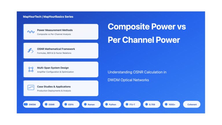
Composite Power Vs Per Channel power for OSNR calculation.

When it comes to optical networks, one of the most critical parameters to consider is the OSNR or Optical Signal-to-Noise Ratio. It measures the signal quality of the optical link, which is essential to ensure proper transmission. The OSNR is affected by different factors, including composite power and per channel power. In this article, we will discuss in detail the difference between these two power measurements and how they affect the OSNR calculation.

What is Composite Power?

Composite power refers to the total power of all the channels transmitted in the optical network. It is the sum of the powers of all the individual channels combined including both the desired signal and any noise or interference.. The composite power is measured using an optical power meter that can measure the total power of the entire signal.

What is Per Channel Power?

Per channel power refers to the power of each channel transmitted in the optical network. It is the individual power of each channel in the network. It provides information on the power distribution among the different channels and can help identify any channel-specific performance issues.The per channel power is measured using an optical spectrum analyzer that can measure the power of each channel separately.

Difference between Composite Power and Per Channel Power

The difference between composite power and per channel power is crucial when it comes to OSNR calculation. The OSNR calculation is affected by both composite power and per channel power. The composite power determines the total power of the signal, while the per channel power determines the power of each channel.

In general, the OSNR is directly proportional to the per-channel power and indirectly influenced by the composite power. This means that as the per-channel power increases, the OSNR also increases. On the other hand, if the composite power becomes too high, it can introduce nonlinear effects in the fiber, potentially degrading the OSNR.

The reason for this is that the noise in the system is mostly generated by the amplifiers used to boost the signal power. As the per channel power decreases, the signal-to-noise ratio decreases, which affects the overall OSNR.

OSNR measures the quality of an optical signal by comparing the power of the desired signal to the power of any background noise or interference within the same bandwidth. A higher OSNR value indicates a better signal quality, with less noise and interference.

Q factor, on the other hand, measures the stability of an optical signal and is related to the linewidth of the optical source. A higher Q factor indicates a more stable and coherent signal.

This acceptable OSNR is delivered through a relatively sophisticated analysis of signal strength per channel, amplifier distances, and the frequency spacing between channels.


OSNR=Pout-L-NF-10 Log N-10 Log[h vv 0

Pout: Per channel output power(dBm)
L:     Attenuation between two amplifiers (dB)
NF :  Noise figure of amplifier(dB)
N:    number of spans
10 Log [h vv0= - 58 dBm1.55μm, 0.1nm spectrum width)     

OSNR=Pout-L-NF-10 Log N-10 Log[h vv 0

The total transmit power is limited by the present laser technology and fiber non linearities .The key factors are the span (L) and the number of spans(N).

To calculate OSNR using per-channel power, you would measure the power of the signal and the noise in each individual channel and then calculate the OSNR for each channel. The OSNR for the entire system would be the average OSNR across all channels.

In general, using per-channel power to calculate OSNR is more accurate, as it takes into account the variations in signal and noise power across the spectrum. However, measuring per-channel power can be more time-consuming and complex than measuring composite power.

Analysis

Following charts are used to deduce the understanding:-

Collected from Real device for Reference

Calculated OSNR and Q factor based on Per Channel Power.

Calculated OSNR and Q factor based on composite Power.

Calculated OSNR and Q factor based on Per Channel Power.

Calculated OSNR and Q factor based on composite Power.

Formulas used for calculation of OSNR, BER and Q factor


Useful Python Script 

import math
def calc_osnr(span_loss, composite_power, noise_figure, spans_count,channel_count):
"""
Calculates the OSNR for a given span loss, power per channel, noise figure, and number of spans.

Parameters:
span_loss (float): Span loss of each span (in dB).
composite_power (float): Composite power from amplifier (in dBm).
noise_figure (float): The noise figure of the amplifiers (in dB).
spans_count (int): The total number of spans.
channel_count (int): The total number of active channels.

Returns:
The OSNR (in dB).
"""
total_loss = span_loss+10*math.log10(spans_count) # total loss in all spans
power_per_channel = composite_power-10 * math.log10(channel_count) # add power from all channels and spans
noise_power = -58 + noise_figure # calculate thermal noise power
signal_power = power_per_channel - total_loss # calculate signal power
osnr = signal_power - noise_power # calculate OSNR
return osnr


osnr = calc_osnr(span_loss=23.8, composite_power=23.8, noise_figure=6, spans_count=3,channel_count=96)
if osnr > 8:
ber = 10* math.pow(10,10.7-1.45*osnr)
qfactor = -0.41667 + math.sqrt(-1.9688 - 2.0833* math.log10(ber)) # calculate OSNR
else:
ber = "Invalid OSNR,can't estimate BER"
qfactor="Invalid OSNR,can't estimate Qfactor"

result=[{"estimated_osnr":osnr},{"estimated_ber":ber},{"estimated_qfactor":qfactor}]
print(result)

Above program can be tested by using exact code at link.


Optical Standards

https://www.itu.int/en/ITU-T/techwatch/Pages/optical-standards.aspx

https://en.wikipedia.org/wiki/ITU-T

ITU-T Handbook

ITU-T Study Group 15 – Networks, Technologies and Infrastructures for Transport, Access and Home

ITU-T Video Tutorial on Optical Fibre Cables and Systems


Recommendations for which ITU-T test specifications are available
ITU-T Recommendations specifying test procedures are available for the following Recommendations:


Optical fibre cables:

  • G.652 (2009-11) Characteristics of a single-mode optical fibre and cable
  • G.653 (2010-07) Characteristics of a dispertion-shifted, single-mode optical fibre and cable
  • G.654 (2010-07) Characteristics of a cut-off shifted, single-mode optical fibre and cable
  • G.655 (2009-11) Characteristics of a non-zero dispersion-shifted single-mode optical fibre and cable
  • G.656 (2010-07) Characteristics of a fibre and cable with non-zero dispersion for wideband optical transport
  • G.657 (2009-11) Characteristics of a bending-loss insensitive single-mode optical fibre and cable for the access network

Characteristics of optical components and subsystems:

  • G.662 (2005-07) Generic characteristics of optical amplifier devices and subsystems
  • G.663 (2011-04) Application related aspects of optical amplifier devices and subsystems
  • G.664 (2006-03) Optical safety procedures and requirements for optical transport systems
  • G.665 (2005-01) Generic characteristics of Raman amplifiers and Raman amplified systems
  • G.666 (2011-02) Characteristics of PMD compensators and PMD compensating receivers
  • G.667 (2006-12) Characteristics of adaptive chromatic dispersion compensators

Optical fibre submarine cable systems:

  • G.973 (2010-07) Characteristics of repeaterless optical fibre submarine cable systems
  • G.974 (2007-07) Characteristics of regenerative optical fibre submarine cable systems
  • G.975.1 (2004-02) Forward error correction for high bit-rate DWDM submarine systems
  • G.977 (2011-04) Characteristics of optically amplified optical fibre submarine cable systems
  • G.978 (2010-07) Characteristics of optical fibre submarine cables