Animated CTA Banner
MapYourTech
MapYourTech has always been about YOUR tech journey, YOUR questions, YOUR thoughts, and most importantly, YOUR growth. It’s a space where we "Map YOUR Tech" experiences and empower YOUR ambitions.
To further enhance YOUR experience, we are working on delivering a professional, fully customized platform tailored to YOUR needs and expectations.
Thank you for the love and support over the years. It has always motivated us to write more, share practical industry insights, and bring content that empowers and inspires YOU to excel in YOUR career.
We truly believe in our tagline:
“Share, explore, and inspire with the tech inside YOU!”
Let us know what YOU would like to see next! Share YOUR thoughts and help us deliver content that matters most to YOU.
Share YOUR Feedback
Tag

Coherent receivers

Browsing

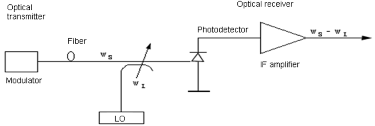
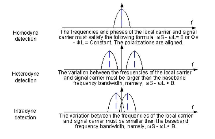
As we know that either homodyne or heterodyne detection can be used to convert the received optical signal into an electrical form. In the case of homodyne detection, the optical signal is demodulated directly to the baseband. Although simple in concept, homodyne detection is difficult to implement in practice, as it requires a local oscillator whose frequency matches the carrier frequency exactly and whose  phase is locked to the incoming signal. Such a demodulation scheme is called synchronous and is essential for homodyne detection. Although optical phase-locked loops have been developed for this purpose, their use is complicated in practice.

Heterodyne detection simplifies the receiver design, as neither optical phase locking nor frequency matching of the local oscillator is required. However, the electrical signal  oscillates rapidly at microwave frequencies and must be demodulated from the IF bandto the baseband using techniques similar to those developed for microwave communication systems. Demodulation can be carried out either synchronously or asynchronously. Asynchronous demodulation is also called incoherent in the radio communication literature. In the optical communication literature, the term coherent detection is used in a wider sense.

A lightwave system is called coherent as long as it uses a local oscillator irrespective of the demodulation technique used to convert the IF signal to baseband frequencies.

*In case of homodyne coherent-detection technique, the local-oscillator frequency is selected to coincide with the signal-carrier frequency.

*In case of heterodyne detection the local-oscillator frequency  is chosen to differ from the signal-carrier frequency.

What Is Coherent Communication?

Definition of coherent light

A coherent light consists of two light waves that:

1) Have the same oscillation direction.

2) Have the same oscillation frequency.

3) Have the same phase or maintain a constant phase relationship with each other. Two coherent light waves produce interference within the area where they meet.

Principles of Coherent Communication

Coherent communication technologies mainly include coherent modulation and coherent detection.

Coherent modulation uses the signals that are propagated to change the frequencies, phases, and amplitudes of optical carriers. (Intensity modulation only changes the strength of light.)

Modulation detection mixes the laser light generated by a local oscillator (LO) with the incoming signal light using an optical hybrid to produce an IF signal that maintains the constant frequency, phase, and amplitude relationships with the signal light.


The motivation behind using the coherent communication techniques is two-fold.

First, the receiver sensitivity can be improved by up to 20 dB compared with that of IM/DD systems.

Second, the use of coherent detection may allow a more efficient use of fiber bandwidth by increasing the spectral efficiency of WDM systems

coherent
#coherent
For coherent signals with wide optical spectrum, the traditional scanning method using an OSA or inband polarization method (EXFO) cannot correctly measure system OSNR. Therefore, use the integral method to measure OSNR of coherent signals.

Perform the following operations to measure OSNR using the integral method:

1.Position the central frequency of the wavelength under test in the middle of the screen of an OSA.
2.Select an appropriate bandwidth span for integration (for 40G/100G coherent signals, select 0.4 nm).
3.Read the sum of signal power and noise power within the specified bandwidth. On the OSA, enable the Trace Integ function and read the integral value. As shown in Figure 2, the integral optical      power (P + N) is 9.68 uW.
4.Read the integral noise power within the specified bandwidth. Disable the related laser before testing the integral noise power. Obtain the integral noise power N within the signal bandwidth      specified in step 2. The integral noise power (N) is 29.58 nW.
5.Calculate the integral noise power (n) within the reference noise bandwidth. Generally, the reference noise bandwidth is 0.1 nm. Read the integral power of central frequency within the bandwidth of 0.1 nm. In this example, the integral noise power within the reference noise bandwidth is 7.395 nW.
6.Calculate OSNR. OSNR = 10 x lg{[(P + N) – N]/n}

In this example, OSNR = 10 x log[(9.68 – 0.02958)/0.007395] = 31.156 dB

osnr


We follow integral method because Direct OSNR Scanning Cannot Ensure Accuracy because of the following reason:

A 40G/100G signal has a larger spectral width than a 10G signal. As a result, the signal spectrums of adjacent channels overlap each other. This brings difficulties in testing the OSNR using the traditional OSA method, which is implemented based on the interpolation of inter-channel noise that is equivalent to in-band noise. Inter-channel noise power contains not only the ASE noise power but also the signal crosstalk power. Therefore, the OSNR obtained using the traditional OSA method is less than the actual OSNR. The figure below shows the signal spectrums in hybrid transmission of 40G and 10G signals with 50 GHz channel spacing. As shown in the figure, a severe spectrum overlap has occurred and the tested ASE power is greater than it should be .As ROADM and OEQ technologies become mature and are widely used, the use of filter devices will impair the noise spectrum. As shown in the following figure, the noise power between channels decreases remarkably after signals traverse a filter. As a result, the OSNR obtained using the traditional OSA method is greater than the actual OSNR..